wheel ISUZU TROOPER 1995 Workshop Manual
[x] Cancel search | Manufacturer: ISUZU, Model Year: 1995, Model line: TROOPER, Model: ISUZU TROOPER 1995Pages: 1928
Page 371 of 1928
REAR WHEEL ANTILOCK BRAKE SYSTEM 5A3-3
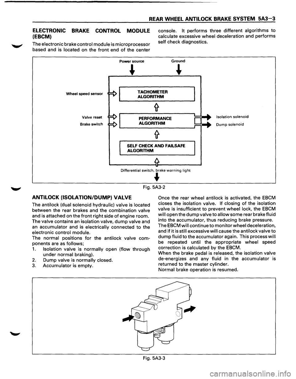
ELECTRONIC BRAKE CONTROL MODULE
(EBCM)
The electronic brake control module is microprocessor
based and is located on the
front end of the center
Power source
console. It performs three different algorithms to
calculate excessive wheel deceleration and performs
self check diagnostics.
Ground
~
Wheel speed sensor TACHOMETER
ALGORITHM
Valve reset
Brake
switch
PERFORMANCE
ALGORITHM o-+ ...
Isolation solenoid
Dump solenoid
SELF CHECK AND FAILSAFE
ALGORITHM
Differential switch, br<'!ke warning light
~
Fig. 5A3-2
ANTILOCK (ISOLATION/DUMP) VALVE
The antilock (dual solenoid hydraulic) valve is located
between the rear brakes and the combination valve
and is attached on the
front right side of engine room.
The valve contains
an isolation valve, dump valve and
an accumulator and is electrically connected to the
electronic control module.
The normal positions
for the antilock valve com
ponents are
as follows;
1. Isolation valve is normally open (flow through
under normal braking).
2. Dump valve is normally closed.
3. Accumulator is empty.
Once the rear wheel antilock is activated, the EBCM
closes the isolation valve. If closing of the isolation
valve is insufficient to prevent wheel lock, the
EBCM
will open the dump valve to allow some rear brake fluid
into the accumulator, thus reducing brake pressure.
The
EBCM will continue to monitor wheel deceleration,
and
if it is still excessive will cause the antilock valve to
dump fluid to the accumulator again. This process will
be repeated until the appropriate wheel speed
correction is calculated by the
EBCM.
When the brake pedal is released, the isolation valve
de-energizes and any fluid in the accumulator is
returned to the master cylinder.
Normal brake operation is resumed.
Fig. 5A3-3
Page 372 of 1928
5A3-4 REAR WHEEL ANTILOCK BRAKE SYSTEM
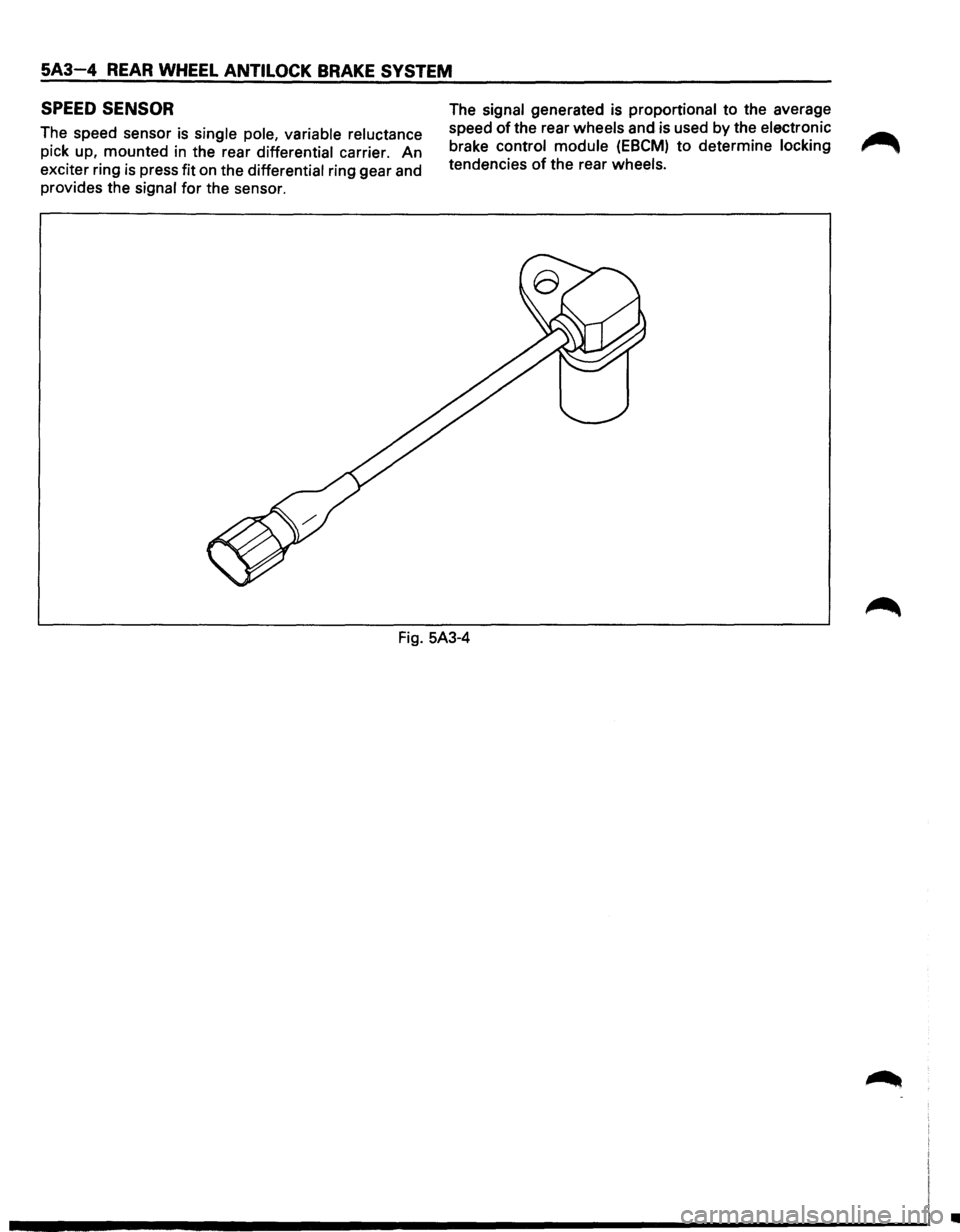
SPEED SENSOR
The speed sensor is single pole, variable reluctance
pick up, mounted
in the rear differential carrier. An
exciter ring
is press fit on the differential ring gear and
provides the signal for the sensor. The
signal generated is proportional
to the average
speed
of the rear wheels and is used by the electronic
brake control module
(EBCM) to determine locking
tendencies
of the rear wheels.
Fig. 5A3-4
•
Page 373 of 1928
REAR WHEEL ANTILOCK BRAKE SYSTEM 5A3-5
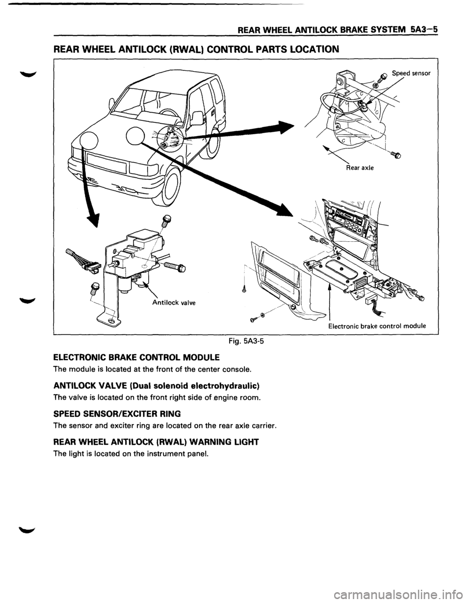
REAR WHEEL ANTILOCK (RWAL} CONTROL PARTS LOCATION
Fig. 5A3-5
ELECTRONIC BRAKE CONTROL MODULE
The module is located at the front of the center console.
ANTILOCK VALVE (Dual solenoid electrohydraulic)
The valve is located on the front right side of engine room.
SPEED SENSOR/EXCITER RING
The sensor and exciter ring are located on the rear axle carrier.
REAR WHEEL ANTILOCK (RWAL) WARNING LIGHT
The light is located on the instrument panel.
Rear axle
Electronic
brake control module
Page 374 of 1928
5A3-6 REAR WHEEL ANTILOCK BRAKE SYSTEM
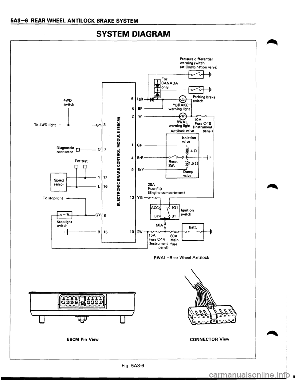
SYSTEM DIAGRAM
4WD
switch
To 4WD
light -----11~-----lGY 3
Diagnostic Of------0 7 connector
For test
1-----11---+--y 17 Speed
sensor 1-----lt-----L
16
To
stoplight -----,
Stoplight switch
•IJI-----B 15
EBCM Pin View
i
&l ~ IU _, :;) Q
~ _, 0 a: .... z
8 IU ~ c( a: liD (.) z 0 a: 1-(.) IU _, IU
Pressure differential warning switch
(at Combination valve)
r-----+-<1 ~+II•
I•
6 LgB Parking brake _.-MI ____ ___,I'\.JI.Jr-, switch
5
BP -----'
2 w ------------~~._~
GR
4 BrR
9 BrY
20A Fuse F-9
RWAL 10
A •
1• h Fuse C-10
warnmg IQ t (Instrument
Antilock valve panel)
Isolation
valve
~ 4il .J o--1> ~
Reset ~1.5il
I
sw.
Dump valve
(Engine compartment)
13 YG -
82 81 switch
50 A
Batt.
10 GW + ,,
15A BOA Fuse C-14 Main (Instrument fuse panel)
RWAL=Rear Wheel Antilock
CONNECTOR View
Fig. 5A3-6
•
Page 375 of 1928
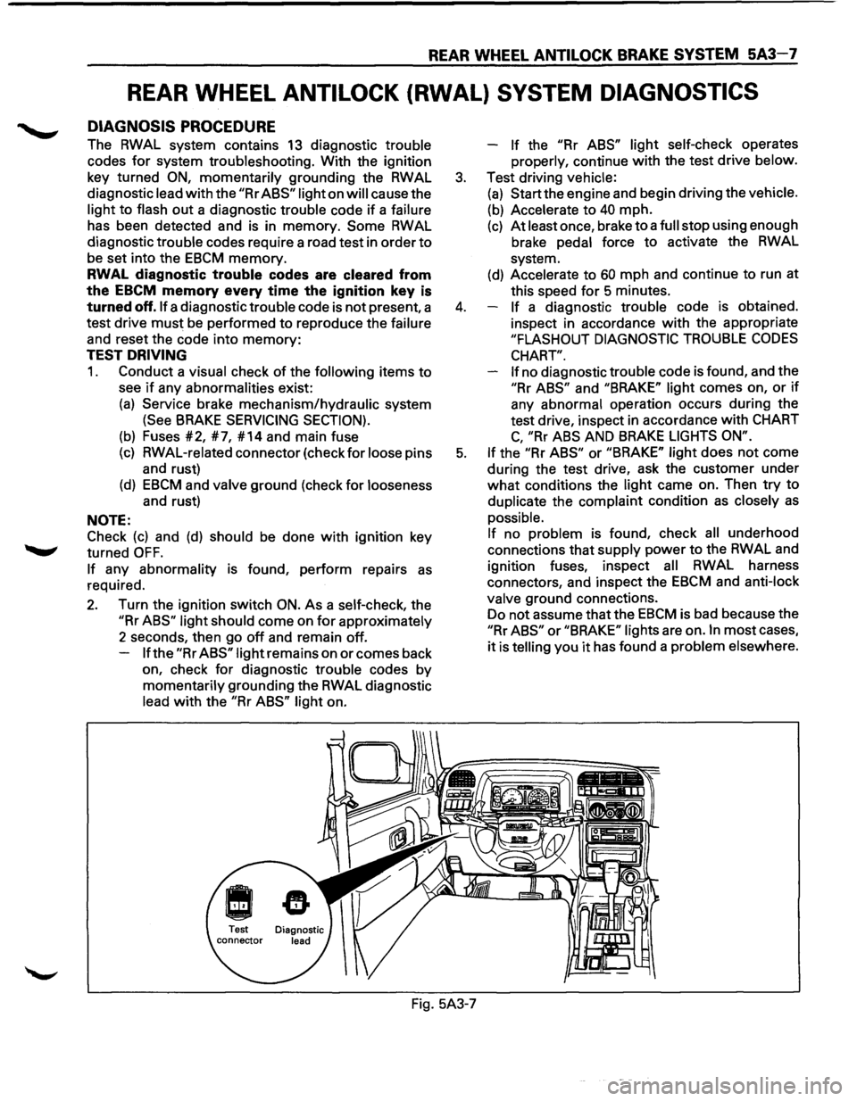
REAR WHEEL ANTILOCK BRAKE SYSTEM 5A3-7
REAR WHEEL ANTILOCK (RWAL) SYSTEM DIAGNOSTICS
DIAGNOSIS PROCEDURE
The RWAL system contains 13 diagnostic trouble
codes
for system troubleshooting. With the ignition
key turned
ON, momentarily grounding the RWAL
diagnostic lead
with the "Rr ABS" light on will cause the
light
to flash out a diagnostic trouble code if a failure
has been detected and is in memory.
Some RWAL
diagnostic trouble codes require a road test in order
to
be set into the EBCM memory.
RWAL diagnostic trouble codes are cleared from
the
EBCM memory every time the ignition key is
turned off. If a diagnostic trouble code is not present, a
test drive
must be performed to reproduce the failure
and reset the code into
memory:
TEST DRIVING
1. Conduct a visual check of the following items to
see if any abnormalities exist:
(a) Service brake mechanism/hydraulic system
(See BRAKE SERVICING SECTION).
(b) Fuses #2, #7, #14 and main fuse
(c) RWAL-related connector (check for loose pins
and rust)
(d) EBCM and valve ground (check for looseness
and rust)
NOTE:
Check
(c) and (d) should be done with ignition key
turned
OFF.
If any abnormality is found, perform repairs as
required.
2. Turn the ignition switch ON. As a self-check, the
"Rr ABS" light should come on for approximately
2 seconds, then go
off and remain off.
If the "Rr ABS" light remains on or comes back
on, check
for diagnostic trouble codes by
momentarily grounding the RWAL diagnostic
lead
with the "Rr ABS" light on. -
If the "Rr
ABS" light self-check operates
properly, continue
with the test drive below.
3. Test driving vehicle:
(a) Start the engine and begin driving the vehicle.
(b) Accelerate to 40 mph.
(c) At least once, brake to a full stop using enough
brake pedal force
to activate the RWAL
system.
(d) Accelerate to 60 mph and continue to run at
this speed
for 5 minutes.
4. If a diagnostic trouble code is obtained.
inspect in accordance
with the appropriate
"FLASHOUT DIAGNOSTIC TROUBLE CODES
CHART".
If
no diagnostic trouble code is found, and the
"Rr ABS" and "BRAKE" light comes on, or if
any abnormal operation occurs during the
test drive, inspect in accordance
with CHART
C, "Rr ABS AND BRAKE LIGHTS ON".
5. If the "Rr ABS" or "BRAKE" light does not come
during the test drive, ask the customer under
what conditions the light came on. Then try to
duplicate the complaint condition
as closely as
possible.
If no problem is found, check all underhood
connections that supply power
to the RWAL and
ignition fuses, inspect
all RWAL harness
connectors, and inspect the
EBCM and anti-lock
valve ground connections.
Do not assume that the
EBCM is bad because the
"Rr ABS" or "BRAKE" lights are on. In most cases,
it is telling you it has found a problem elsewhere.
Fig. 5A3-7
Page 376 of 1928
5A3-8 REAR WHEEL ANTILOCK BRAKE SYSTEM
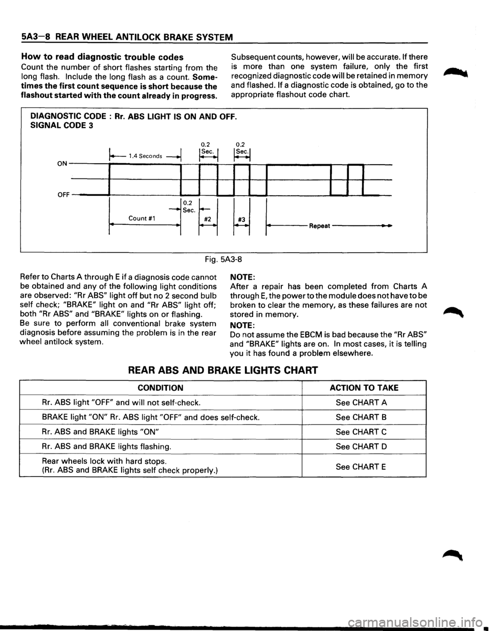
How to read diagnostic trouble codes
Count the number of short flashes starting from the
long flash. Include the long flash as a count. Some
times the first count sequence is short because the
flashout started with the count already in progress.
Subsequent counts, however, will be accurate. If there
is more than one system
failure, only the first
recognized diagnostic code
will be retained in memory
and flashed. If a diagnostic code is obtained, go to the
appropriate
flashout code chart.
DIAGNOSTIC CODE : Rr. ABS LIGHT IS ON AND OFF.
SIGNAL CODE 3
0.2 0.2 I I !Sec. I !Sec.! r--1.4 Seconds --+j ~ t--1
ON-------,~-----------,--~--~~~-r--?-----------~--r--r-----
OFF ~' ----L-1--'-----11 IL....-l.-1 ~I I ______..l__.__l ..____I
0.2~ ~ ~
-Sec.
Count #1 #2 #3 r----~ Repeat---
Fig. 5A3-8
Refer
to Charts A through E if a diagnosis code cannot
be obtained and any
of the following light conditions
are observed:
"Rr ABS" light off but no 2 second bulb
self
check; "BRAKE" light on and "Rr ABS" light off;
both
"Rr ABS" and "BRAKE" lights on or flashing.
Be sure to perform all conventional brake system
diagnosis before assuming the
problem is in the rear
wheel antilock system.
NOTE:
After a repair has been completed from Charts A
through
E, the power to the module does not have to be
broken to
clear the memory, as these failures are not
stored in memory.
NOTE:
Do not assume the EBCM is bad because the "Rr ABS"
and "BRAKE" lights are on. In most cases, it is telling
you it has found a problem elsewhere.
REAR ABS AND BRAKE LIGHTS CHART
CONDITION ACTION TO TAKE
Rr. ABS light "OFF" and will not self-check.
See CHART A
BRAKE light "ON" Rr. ABS light "OFF" and does self-check.
See CHART B
Rr. ABS and BRAKE lights "ON"
See CHART C
Rr. ABS and BRAKE lights flashing.
See CHART D
Rear
wheels lock with hard stops. See CHART E (Rr. ABS and BRAKE lights self check properly.)
Page 377 of 1928
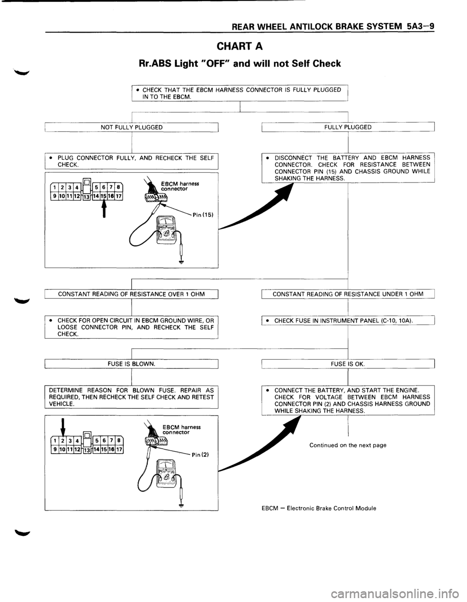
REAR WHEEL ANTILOCK BRAKE SYSTEM 5A3-9
CHART A
Rr.ABS Light "OFF" and will not Self Check
• CHECK THAT THE EBCM HARNESS CONNECTOR IS FULLY PLUGGED IN TO THE EBCM.
• PLUG CONNECTOR FULLY, AND RECHECK THE SELF
CHECK.
• CHECK FOR OPEN CIRCUIT IN EBCM GROUND WIRE, OR LOOSE CONNECTOR PIN, AND RECHECK THE SELF
CHECK.
DETERMINE REASON FOR BLOWN FUSE. REPAIR AS
REQUIRED, THEN RECHECK THE SELF CHECK AND RETEST VEHICLE. •
DISCONNECT
THE BATTERY AND EBCM HARNESS
CONNECTOR. CHECK FOR RESISTANCE BETWEEN
CONNECTOR PIN (15) AND CHASSIS GROUND WHILE
SHAKING THE HARNESS.
• CONNECT THE BATTERY, AND START THE ENGINE. CHECK FOR VOLTAGE BETWEEN EBCM HARNESS
CONNECTOR PIN (2) AND CHASSIS HARNESS GROUND WHILE SHAKING THE HARNESS.
Continued on the next page
EBCM
~ Electronic Brake Control Module
Page 378 of 1928
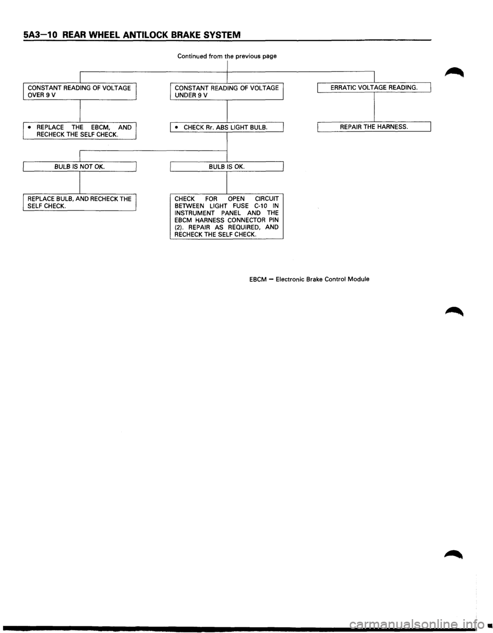
5A3-1 0 REAR WHEEL ANTI LOCK BRAKE SYSTEM
Continued from the previous page
I
I
I CONSTANT READING OF VOLTAGE J CONSTANT READING OF VOLTAGE I ERRATIC VOLTAGE READING. I OVER 9 V
UNDER 9 V
I ,. REPLACE THE EBCM, AND I • CHECK Rr. ABS LIGHT BULB. I REPAIR THE HARNESS. I RECHECK THE SELF CHECK.
I
I BULB IS NOT OK. I BULB IS OK.
1 I REPLACE BULB, AND RECHECK THE J CHECK FOR OPEN CIRCUIT
SELF CHECK. BETWEEN LIGHT FUSE C-10 IN INSTRUMENT PANEL AND THE EBCM HARNESS CONNECTOR PIN (2). REPAIR AS REQUIRED, AND RECHECK THE SELF CHECK.
EBCM
-Electronic Brake Control Module
•
Page 379 of 1928
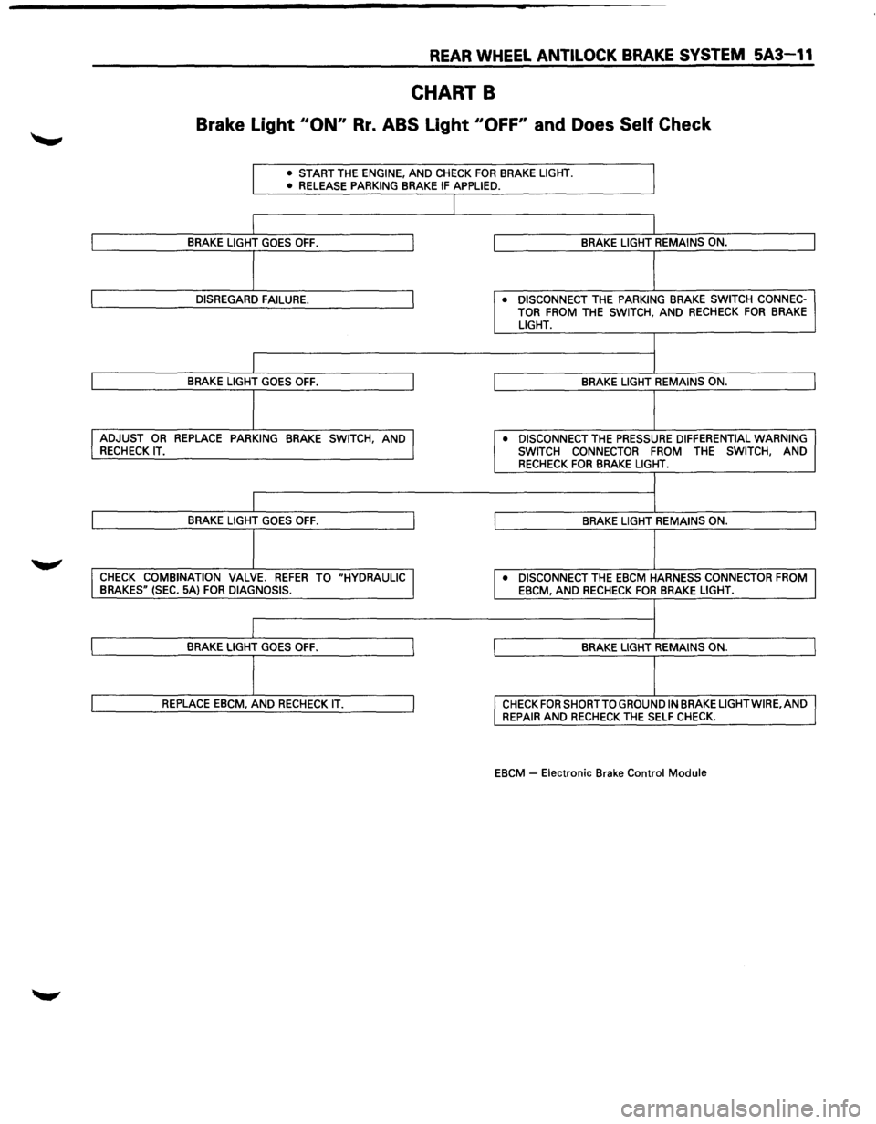
REAR WHEEL ANTILOCK BRAKE SYSTEM 5A3-11
CHART B
Brake Light 110N" Rr. ABS Light "OFF' and Does Self Check
• START THE ENGINE, AND CHECK FOR BRAKE LIGHT.
• RELEASE PARKING BRAKE IF APPLIED.
J
I
I BRAKE LIGHT GOES OFF. J BRAKE LIGHT REMAINS ON.
I
I DISREGARD FAILURE. J • DISCONNECT THE PARKING BRAKE SWITCH CONNEC-
TOR FROM THE SWITCH, AND RECHECK FOR BRAKE LIGHT.
I
I
I BRAKE LIGHT GOES OFF. I BRAKE LIGHT REMAINS ON.
I I ADJUST OR REPLACE PARKING BRAKE SWITCH, AND J • DISCONNECT THE PRESSURE DIFFERENTIAL WARNING RECHECK IT.
SWITCH CONNECTOR
FROM THE SWITCH, AND RECHECK FOR BRAKE LIGHT.
I
I
I BRAKE LIGHT GOES OFF. I BRAKE LIGHT REMAINS ON.
j
I CHECK COMBINATION VALVE. REFER TO "HYDRAULIC I • DISCONNECT THE EBCM HARNESS CONNECTOR FROM
BRAKES" (SEC. 5A) FOR DIAGNOSIS.
EBCM, AND RECHECK FOR BRAKE LIGHT.
I
I
I BRAKE LIGHT GOES OFF. I BRAKE LIGHT REMAINS ON.
I
I REPLACE EBCM, AND RECHECK IT. I CHECK FOR SHORT TO GROUND IN BRAKE LIGHTWIRE,AND
REPAIR AND RECHECK THE SELF CHECK.
EBCM
= Electronic Brake Control Module
Page 380 of 1928
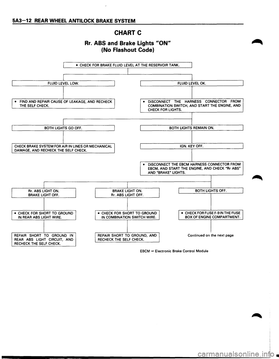
5A3~12 REAR WHEEL ANTILOCK BRAKE SYSTEM
CHART C
Rr. ABS and Brake Lights 110N"
(No Flashout Code}
I • CHECK FOR BRAKE FLUID LEVEL AT THE RESERVOIR TANK.
I
I FLUID LEVEL LOW. I FLUID LEVEL OK.
I
• FIND AND REPAIR CAUSE OF LEAKAGE, AND RECHECK I • DISCONNECT THE HARNESS CONNECTOR FROM THE
SELF CHECK. COMBINATION SWITCH, AND START THE ENGINE, AND CHECK FOR LIGHTS.
I BOTH LIGHTS GO OFF. I BOTH LIGHTS REMAIN ON.
I
CHECK BRAKE SYSTEM FOR AIR IN LINES OR MECHANICAL I IGN. KEY OFF. DAMAGE, AND RECHECK THE SELF CHECK.
• DISCONNECT THE EBCM HARNESS CONNECTOR FROM EBCM, AND START THE ENGINE, AND CHECK uRr ABS" AND UBRAKE" LIGHTS.
I Rr. ABS LIGHT ON.
I
BRAKE LIGHT ON.
I I BOTH LIGHTS OFF. BRAKE LIGHT OFF. Rr. ABS LIGHT OFF.
I • CHECK FOR SHORT TO GROUND I • CHECK FOR SHORT TO GROUND I I
• CHECK FOR FUSE F-91N THE FUSE IN REAR ABS LIGHT WIRE. IN COMBINATION SWITCH WIRE. BOX OF ENGINE COMPARTMENT.
I I REPAIR
SHORT TO GROUND IN I REPAIR SHORT TO GROUND, AND J Continued on the next page REAR ABS LIGHT CIRCUIT, AND RECHECK THE SELF
CHECK.
RECHECK THE SELF CHECK.
EBCM -
Electronic Brake Control Module
•