turn signal ISUZU TROOPER 1995 Workshop Manual
[x] Cancel search | Manufacturer: ISUZU, Model Year: 1995, Model line: TROOPER, Model: ISUZU TROOPER 1995Pages: 1928
Page 60 of 1928
1 B-6 AIR CONDITIONING
ELECTRONIC THERMOSTAT
The thermostat consists of the thermosensor and
thermostat unit which functions electrically to
reduce the noises being generated while the system
is in operation.
The
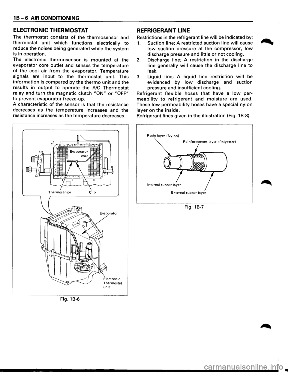
electronic thermosensor is mounted at the
evaporator core outlet and senses the temperature
of the cool air from the evaporator. Temperature
signals are input to the thermostat unit. This
information is compared by the thermo unit and the
results in output to operate the A/C Thermostat
relay and turn the magnetic clutch "ON" or "OFF"
to prevent evaporator freeze-up.
A characteristic
of the sensor is that the resistance
decreases as the
temperature increases and the
resistance increases as
the temperature decreases.
Thermosensor Clip
Evaporator
unit
Fig. 18-6
REFRIGERANT LINE
Restrictions in the refrigerant line will be indicated by:
1. Suction line; A restricted suction line will cause
low suction pressure at the compressor, low
discharge pressure and little or not cooling.
2. Discharge line; A restriction in the discharge
line generally will cause the discharge line to
leak.
3. Liquid line; A liquid line restriction will be
evidenced
by low discharge and suction
pressure and
insufficient cooling.
Refrigerant flexible hoses that have a low per
meability to refrigerant and moisture are used.
These
low permeability hoses have a special nylon
layer on the inside.
Refrigerant
lines given in the illustration (Fig. 1 B-8).
Resin layer (Nylon)
Reinforcement layer (Polyester)
External rubber layer
Fig. 1 B-7
•
Page 128 of 1928
3-8 DIAGNOSIS
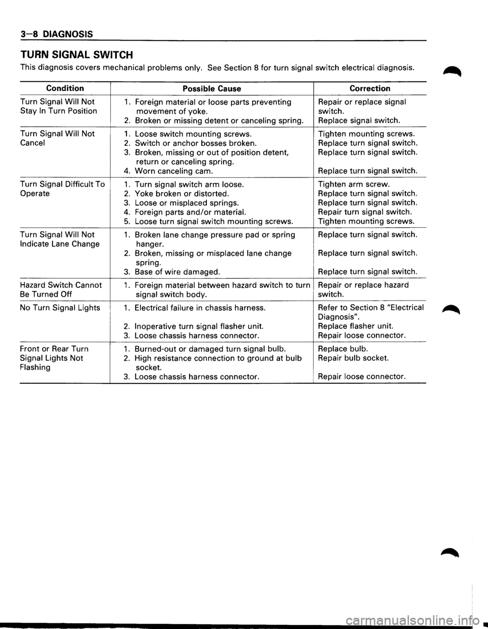
TURN SIGNAL SWITCH
This diagnosis covers mechanical problems only. See Section 8 for turn signal switch electrical diagnosis. ~
Condition Possible Cause Correction
Turn Signal
Will Not 1. Foreign material or loose parts preventing Repair or replace
signal
Stay
In Turn Position movement of yoke. switch.
2. Broken or missing detent or canceling spring. Replace
signal switch.
Turn Signal
Will Not 1. Loose switch mounting screws. Tighten mounting screws.
Cancel
2. Switch or anchor bosses broken. Replace
turn signal switch.
3. Broken, missing or out of position detent, Replace
turn signal switch.
return
or canceling spring.
4. Worn canceling cam. Replace
turn signal switch.
Turn Signal Difficult To
1. Turn signal switch arm loose. Tighten
arm screw.
Operate
2. Yoke broken or distorted. Replace
turn signal switch.
3. Loose or misplaced springs. Replace
turn signal switch.
4. Foreign parts and/or material. Repair
turn signal switch.
5. Loose turn signal switch mounting screws. Tighten mounting screws.
Turn Signal Will Not
1 . Broken lane change pressure pad or spring Replace
turn signal switch.
Indicate Lane Change
hanger.
2. Broken, missing or misplaced lane change Replace
turn signal switch.
spring.
3. Base of wire damaged. Replace
turn signal switch.
Hazard Switch Cannot
1. Foreign material between hazard switch to turn Repair
or replace hazard
Be Turned Off
signal switch body. switch.
No Turn Signal Lights
1. Electrical failure in chassis harness. Refer to Section
8 "Electrical
Diagnosis".
2. Inoperative turn signal flasher unit. Replace
flasher unit.
3. Loose chassis harness connector. Repair
loose connector.
Front or Rear Turn
1. Burned-out or damaged turn signal bulb. Replace
bulb.
Signal Lights
Not 2. High resistance connection to ground at bulb Repair
bulb socket.
Flashing socket.
3. Loose chassis harness connector. Repair
loose connector.
•
Page 369 of 1928
REAR WHEEL ANTILOCK BRAKE SYSTEM 5A3-1
SECTION 5A3
REAR WHEEL ANTILOCK BRAKE SYSTEM
(RWAL}
w CAUTION:
• All brake attaching fasteners are an important attaching part in that they could affect performance of vital
parts and systems, and/or could result in major repair expense. They must be replaced with one of the same
part
number or with an equivalent part if replacement becomes necessary. Do not use replacement parts of
lesser quality or substitute design. Torque values must be used as specified during reassembly to assure
proper retention of these parts.
CONTENTS
Introduction . . . . . . . . . . . . . . . . . . . . . . . . . 5A3· 1
General Description . .
. . . . . . . . . . . . . . .
5A3· 1
Rear
Wheel Antilock (RWAL) Control
Parts Location . .
. . . . . . . . . . . . . . . . .
5A3· 5
System Diagram . .
. . . . . . . . . . . . . . . . . . . .
5A3· 6
Rear
Wheel Antilock (RWAL) System
Diagnostics . .
. . . . . . . . . . . . . . . . . . . . . .
5A3· 7
On-Vehicle Service . .
. . . . . . . . . . . . . . . . .
5A3·38
RWAL Electronic Brake Control
Module (EBCM) Replacement ....... 5A3-38
Antilock
(Isolation/Dump) Valve
Replacement ..................... 5A3-39
Speed Sensor Replacement
.......... 5A3-40
Main Data and Specifications ........... 5A3-41
Torque Specifications
............... 5A3-41
INTRODUCTION
This section deals with the complete diagnosis and
services
for vehicles equipped with rear wheel
antilock.
For service information regarding all other
components
of the brake system, refer to "Hydraulic
Brakes"
(Sec. SA), "Brake Booster System" (Sec. SA 1)
or "Disc Brakes" (Sec. SA2) of this Manual.
GENERAL DESCRIPTION
The rear wheel anti lock system (RWAL) is designed to
reduce rear wheel lock-up during a severe brake
application,
thus maintaining rear end stability. The
system functions
by regulating the rear hydraulic
brake line pressure. The pressure regulation is
accomplished
by an anti lock valve which is located on
the
front right side of engine room. The anti lock valve
is made up of two valves, a dump valve which releases
pressure into an accumulator and an isolation valve
which maintains rear brake pressure. The valve is
controlled
by a microcomputer which is part of the
Electronic Brake Control Module (EBCM). The
EBCM is mounted at the
front of the center
console. Under severe brake application, as pressure
is
applied to the brake pedal, the EBCM is designed to
permit the valve to do one of three functions or a
combination
of all three. The EBCM will allow the valve
to either maintain the same amount of hydraulic
pressure, release hydraulic pressure through the
dump valve into the accumulator or increase the
pressure by
pulsing the isolation valve.
The EBCM operates by receiving signals from the
speed sensor (which
is located in the differential
carrier), combination
valve and the brake light switch.
The RWAL system is connected
to the RWAL indicator
light located on the dash. An indication of the RWAL
operation and a
bulb check is performed each time the
ignition is turned
"ON". The indicator light will remain
on
for about two seconds. A RWAL system
malfunction is indicated if the RWAL indicator light
stays on, or comes on during driving. To determine the
specific
trouble, refer to "RWAL System Diagnostics"
in this section.
Page 413 of 1928
4-WHEEL ANTILOCK BRAKE SYSTEM (ABS) 5A4-3
GENERAL DESCRIPTION
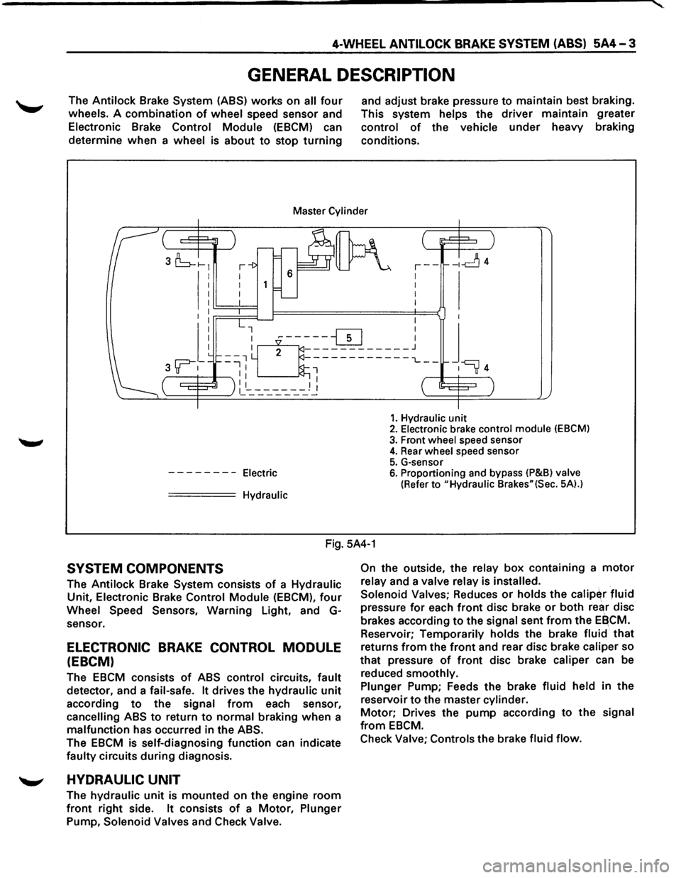
The Antilock Brake System (ASS) works on all four
wheels. A combination of wheel speed sensor and
Electronic Brake Control Module (EBCM) can
determine
when a wheel is about to stop turning
and adjust brake pressure to maintain best braking.
This system
helps the driver maintain greater
control of the vehicle under heavy braking
conditions.
Master Cylinder
I I I I
--------Electric
===== Hydraulic
,--1 I
I
I
-ld4
1. Hydraulic unit 2. Electronic brake control module (EBCM)
3. Front wheel speed sensor 4. Rear wheel speed sensor
5. G-sensor 6. Proportioning and bypass (P&Bl valve
(Refer to "Hydraulic Brakes"(Sec. 5A).)
Fig. 5A4-1
SYSTEM COMPONENTS
The Antilock Brake System consists of a Hydraulic
Unit, Electronic Brake Control Module (EBCM), four
Wheel Speed Sensors, Warning Light, and G
sensor.
ELECTRONIC BRAKE CONTROL MODULE
(EBCM)
The EBCM consists of ABS control circuits, fault
detector, and a fail-safe. It drives the hydraulic unit
according to the signal from each sensor,
cancelling ABS to return to normal braking when a
malfunction has occurred in the ABS.
The EBCM is self-diagnosing function can indicate
faulty circuits during diagnosis.
'--" HYDRAULIC UNIT
The hydraulic unit is mounted on the engine room
front right side. It consists of a Motor, Plunger
Pump, Solenoid Valves and Check Valve. On
the
outside, the relay box containing a motor
relay and a valve relay is installed.
Solenoid Valves;
Reduces or holds the calip~r fluid
pressure for each front disc brake or both rear disc
brakes according
to the signal sent from the EBCM.
Reservoir;
Temporarily holds the brake fluid that
returns from the front and rear disc brake caliper so
that pressure of front disc brake caliper can be
reduced
smoothly.
Plunger
Pump; Feeds the brake fluid held in the
reservoir
to the master cylinder.
Motor; Drives the pump according to the signal
from EBCM.
Check
Valve; Controls the brake fluid flow.
Page 414 of 1928
5A4-4 4-WHEEL ANTILOCK BRAKE SYSTEM (ABS)
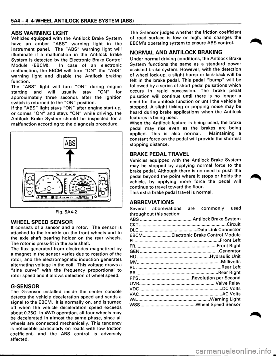
ABS WARNING LIGHT
Vehicles equipped with the Antilock Brake System
have an
amber "ABS" warning light in the
instrument panel. The "ABS" warning light will
illuminate if a malfunction in the Antilock Brake
System is detected by the Electronic Brake
Control
Module (EBCM). In case of an electronic
malfunction, the EBCM will turn "ON" the "ABS"
warning light and disable the Antilock braking
function.
The
"ABS" light will turn "ON" during engine
starting and
will usually stay "ON" for
approximately three seconds after the ignition
switch is returned to the "ON" position.
If the "ABS" light stays "ON" after engine start-up,
or comes "ON" and stays "ON" while driving, the
Antilock Brake System should be inspected
for a
malfunction according to the diagnosis procedure.
Fig. 5A4-2
WHEEL SPEED SENSOR
It consists of a sensor and a rotor. The sensor is
attached
to the knuckle on the front wheels and to
the axle shaft bearing holder on the rear wheels.
The
rotor is press-fit in the axle shaft.
The
flux generated from electrodes magnetized by
a magnet in the sensor varies due to rotation of the
rotor, and the electromagnetic
induction generates
alternating voltage in
the coil. This voltage draws a
"sine curve" with the frequency proportional to
rotor speed and it allows detection of wheel speed.
G-SENSOR
The G-sensor installed inside the center console
detects the vehicle deceleration speed and sends a
signal
to the EBCM. It is normally on, and is turned
off when the vehicle deceleration speed exceeds
about 0.35G.
In 4WD operation, all four wheels may
be decelerated in almost the same phase, since all
wheels are connected mechanically. This tendency
is noticeable particularly on roads
with low friction
coefficient, and the
ABS control is adversely
affected. The
G-sensor judges
whether the friction coefficient
of road surface is low or high, and changes the
EBCM's operating system to ensure ABS control.
NORMAL AND ANTILOCK BRAKING
Under normal driving conditions, the Antilock Brake
System functions the same
as a standard power
assisted brake system. However, with the detection
of wheel lock-up, a slight bump or kick-back will be
felt in the brake pedal. This pedal
"bump" will be
followed by a series of short pedal pulsations which
occurs in rapid succession. The brake pedal
pulsation
will continue until there is no longer a
need
for the antilock function or until the vehicle is
stopped. A
slight ticking or popping noise may be
heard
during brake applications when the Antilock
features is being used.
When the
Antilock feature is being used, the brake
pedal
may rise even as the brakes are being
applied. This is also
normal. Maintaining a
constant force on the pedal
will provide the shortest
stopping distance.
BRAKE PEDAL TRAVEL
Vehicles equipped with the Antilock Brake System
may be stopped by applying normal force to the
brake pedal.
Although there is no need to push the
pedal beyond the
point where it stops or holds the ~
vehicle, by applying more force the pedal will
continue to travel toward the floor.
This extra brake pedal travel is normal.
ABBREVIATIONS
Several abbreviations are commonly used
throughout this section:
ABS .......................................... Antilock Brake System
CKT ...................................................................... Circuit
DLC ............................................... Data Link Connector
EBCM ....................... Eiectronic Brake Control Module
FL. ................................................................... Front Left
FR ................................................................. Front Right
GEN ............................................................... Generator
HU .......................................................... Hydraulic Unit
MV ................................................................... Millivolts
RL .................................................................... Rear Left
RR ................................................................. Rear Right
RPS .......................................... Revolution per Second
UVR ............................................................. Valve Relay
VDC .................................................................. DC Volts
VAC .................................................................. AC Volts
W/L .........................................................
Warning Light
WSS ............................................ Wheel Speed Sensor
Page 644 of 1928
6C - 2 ENGINE FUEL
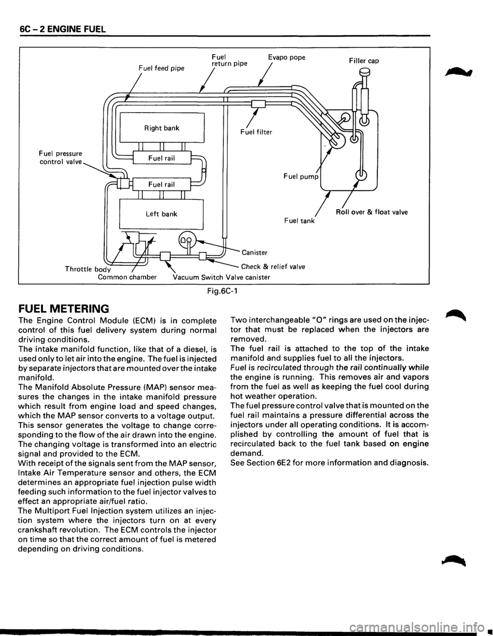
Fuel
Fuel
feed pipe return pipe Evapo pope
Fuel pressure
control valve Right
bank
Left bank Fuel tank
Canister
Throttle body Common chamber
Check & relief
valve
Vacuum Switch Valve canister
Fig.6C-1
FUEL METERING
The Engine Control Module (ECM) 1s 1n complete
control of this fuel delivery system during normal
driving conditions.
The intake manifold function, like that of a diesel, is
used
only to let air into the engine. The fuel is injected
by separate injectors that are mounted over the intake
manifold.
The Manifold Absolute Pressure (MAP) sensor mea
sures
the changes in the intake manifold pressure
which result from engine load and speed changes,
which the MAP sensor converts to a voltage output.
This sensor generates the voltage to change corre
sponding to the flow ofthe air drawn into the engine.
The
changing voltage is transformed into an electric
signal and provided to the ECM.
With receipt of the signals sent from the MAP sensor,
Intake Air Temperature sensor and others, the ECM
determines an appropriate fuel injection pulse width
feeding such information to the fuel injector valves to
effect an appropriate air/fuel ratio.
The
Multipart Fuel Injection system utilizes an injec
tion system where the injectors turn on at every
crankshaft revolution. The ECM controls the injector
on time so that the correct amount of fuel is metered
depending on driving conditions.
Two interchangeable "0" rings are used on the injec
tor that must be replaced when the injectors are
removed.
The fuel rail is attached to the top of the intake
manifold and supplies fuel to all the injectors.
Fuel is recirculated
through the rail continually while
the engine is running. This removes air and vapors
from the fuel as well as keeping the fuel cool during
hot weather operation.
The fuel pressure control valve that is mounted on the
fuel rail maintains a pressure differential across the
injectors under all operating conditions. It is accom
plished by controlling the amount of fuel that is
recirculated back
to the fuel tank based on engine
demand.
See Section 6E2 for more information and diagnosis.
;au
•
Page 689 of 1928
IGNITION SYSTEM 6D4 - 1
SECTION 604
IGNITION SYSTEM
CONTENTS
General Description ...................... .
Diagnosis
................................... .
On-Vehicle Service ....................... .
Spark Plug Wire ....................... .
Spark Plug .............................. . 6D4-1
6D4-2 6D4-3
6D4-3
6D4-3
Electronic Ignition (EI) Assembly ...
Crankshaft Position Sensor
(CKP sensor) ........................ .
Torque Specifications
................ .
Main Data and Specifications
......... . 6D4-5
6D4-5
6D4-6
6D4-7
GENERAL DESCRIPTION
Ignition is done by the Electronic Ignition (EI) that
fires directly the ignition plugs from ignition coils
through spark plug wires without using a distributor.
A pair of ignition coils for the cylinders having differ
ent phases by 360° (No.1 and No.4, No.2 and No.5,
No.3 and No.6) are
fired simultaneously.
Since the cylinder on exhaust stoke requires less
energy to fire its ignition plug, energy from the
ignition coils can be utilized to fire the mating cylin
der on compression stroke. After additional 360°
rotation, respective cylinder stokes are reversed.
TheEl consists of three ignition coils, ignition control
module, crank angle sensor, Engine Control Module
(ECM) and other components.
Module is provided under the ignition coil, connected
with ECM by means of 6-pin connector. The
ignition control module turns on/off the primary
circuit of ignition coils, and also it controls the igni
tion timing at the engine
speed below 538 rpm.
A notch in
the timing disc on the crankshaft activates
the crank angle sensor which then sends information
such as firing order and starting timing of each
ignition coil to the ECM.
Further, the El employs Ignition Control (I C) to control
similar to a distributor system.
By receiving
signals such as crank position, engine
speed, water temperature and Manifold Absolute
Pressure (MAP), the ECM controls the ignition timing.
Page 708 of 1928
6E2-12 DRIVEABILITY AND EMISSIONS
L-LITER
A metric unit of capacity.
MALFUNCTION
A problem that causes the system to operate
incorrectly. Typical malfunctions are wiring harness
opens
or shorts, failed sensors or circuit components.
MAP-MANIFOLD ABSOLUTE PRESSURE
Air pressure in the intake manifold with reference to
zero or absolute vacuum.
MPH-MILE PER HOUR
A unit measuring speed needed to travel distance of
one mile (5280 feet) in one hour.
MIT -MANUAL TRANSMISSION
N.C.-NORMALLY CLOSED
State of relay contacts or solenoid plunger is close
when voltage is not applied.
N·m-NEWTON METER (Torque)
A metric unit describing force.
N.M.-NORMALLY OPEN
State of relay contacts or solenoid plung&r' is open
when voltage is applied.
NOx-NITROGEN OXIDES
One of the pullutants found in engirie exhaust.
02-0XYGEN (Sensor)
Monitors the oxygen contel)f of the exhaust system
and generates a
voltage signal to the Engine Control
Module (ECM).
OUTPUT
Result of a functi typically controlled by the ECM.
OXYGEN SE OR
Device that etects the amount of oxygen (02) in the
exhaust
stfeam. /
PCV-~OSITIVE CRANKCASE VENTILATION
Prey£nt fumes in crankcase from passing into
atmosphere.
PNP-PARK/NEUTRAL POSITION
PORT-EXHAUST OR INTAKE PORT
PWM-PULSE WIDTH MODULATE
RPM-REVOLUTION PER MINUTE
A measure of rotational speed.
SELF-DIAGNOSTIC TROl)SLE CODE
The ECM can detect malfunctions in the system. If a
malfunction occurs, the ECM turns on the malfunction
indicator lamp. A OTC can be obtained from the ECM
through the malfunction indicator lamp. This DTC will
indicate the area of the malfunction.
TACH-TACHOMETER
TB-THROTTLE BODY
TBI-THROTTLE BODY FUEL INJECTION
Computer Command Control using throttle body fuel
injection
TP SENSOR-THROTTLE POSITION SENSOR
VACUUM
Negative pressure; less than atmospheric pressure.
VIN-VEHICLE IDENTIFICATION NUMBER
VSS-VEHICLE SPEED SENSOR
Sensor which sends vehicle speed information to the
ECM.
VSV-VACUUM SWITCH VALVE
(Electronically Controlled)
VSV-VACUUM SWITCH VALVE
Temperature controlled vacuum switch, that is used to
route or exhaust vacuum at various engine
temperatures.
WOT -WIDE OPEN THROTTLE
DRIVEABILITV AND EMISSION SECTION SUMMARY
The Driveability and Emissions Sections are sub
divided into three sub sections:
SECTION A: CIRCUIT INFORMATION &
DIAGNOSIS
• Component Locations
• Wiring Diagrams
• ECM Terminal End View and Terminal
Definitions
• On-Board Diagnostic System Check. This
must be the first step of any diagnostic
procedure.
• DTC Charts with facing pages containing
circuit diagrams, circuit operation
information, and
helpful diagnostic
information.
SECTION B: DRIVEABILITY & EMISSIONS
SYMPTONS
• This sub-section assists in diagnosis of
intermittent problems or problems which
don't result in the storing of DTC(s). It is
arranged
by symptoms of poor driveability
and emissions and lists possible causes of
the problems.
SECTION C: COMPONENT CHECKS &
SERVICE
• Component and Circuit Descriptions
• On-Vehicle Service
• Functional
Checks/Diagnostic Charts
•
Page 756 of 1928
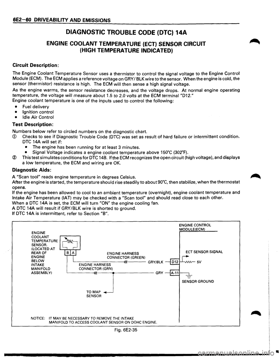
6E2-60 DRIVEABILITY AND EMISSIONS
DIAGNOSTIC TROUBLE CODE (DTC) 14A
ENGINE COOLANT TEMPERATURE (ECT) SENSOR CIRCUIT
(HIGH
TEMPERATURE INDICATED)
Circuit Description:
The Engine Coolant Temperature Sensor uses a thermistor to control the signal voltage to the Engine Control
Module
(ECM). The ECM applies a reference voltage on GRY I 8LK wire to the sensor. When the engine is cold, the
sensor (thermistor) resistance is high. The
ECM will then sense a high signal voltage.
As the engine warms, the sensor resistance decreases, and the voltage drops. At normal engine operating
temperature, the
voltage will measure about 1.5 to 2.0 volts at the ECM terminal "D12."
Engine coolant temperature is one of the inputs used to control the following:
• Fuel delivery
• Ignition control
• Idle
Air Control
Test Description:
Numbers below refer to circled numbers on the diagnostic chart.
CD Checks to see if Diagnostic Trouble Code (DTC) was set as result of hard failure or intermittent condition.
DTC 14A will set if:
• The engine has been running for at least 3 minutes.
• Signal Voltage indicates a engine coolant temperature above 15o•c (302.F).
® This test simulates conditions for DTC 148. lfthe ECM recognizes the open circuit (high voltage), and displays
a low temperature, the ECM and wiring are OK.
Diagnostic Aids:
A "Scan tool" reads engine temperature in degrees Celsius.
After the engine is started, the temperature should rise steadily to about so·c, then stabilize, when the thermostat
opens.
If the engine has been allowed to cool to an ambient temperature (overnight), engine coolant temperature and
Intake Air Temperature (IAT) may be checked with a "Scan tool" and should read close to each other.
When a
DTC 14A is set, the ECM will turn "ON" the engine cooling fan.
A
DTC 14A will result if GRY /8LK wire is shorted to ground.
If DTC 14A is intermittent, refer to Section "8".
ENGINE
COOLANT
TEMPERATURE SENSOR. (LOCATED AT REAR OF ENGINE
BELOW
INTAKE
MANIFOLD
ASSEMBLY) ENGINE
HARNESS CONNECTOR(GREEN) L----------<~---GRY/BLK ENGINE HARNESS
CONNECTOR (GRN)
L__ ___ T_O~M(~A-P-~-~-------GRY
SENSOR
NOTICE: IT
MAY BE NECESSARY TO REMOVE THE INTAKE
MANIFOLD TO ACCESS COOLANT SENSOR ON DOHC ENGINE.
Fig. 6E2-35
ENGINE CONTROL MODULE(ECM)
ECT SENSOR SIGNAL
SENSOR GROUND
•
Page 768 of 1928
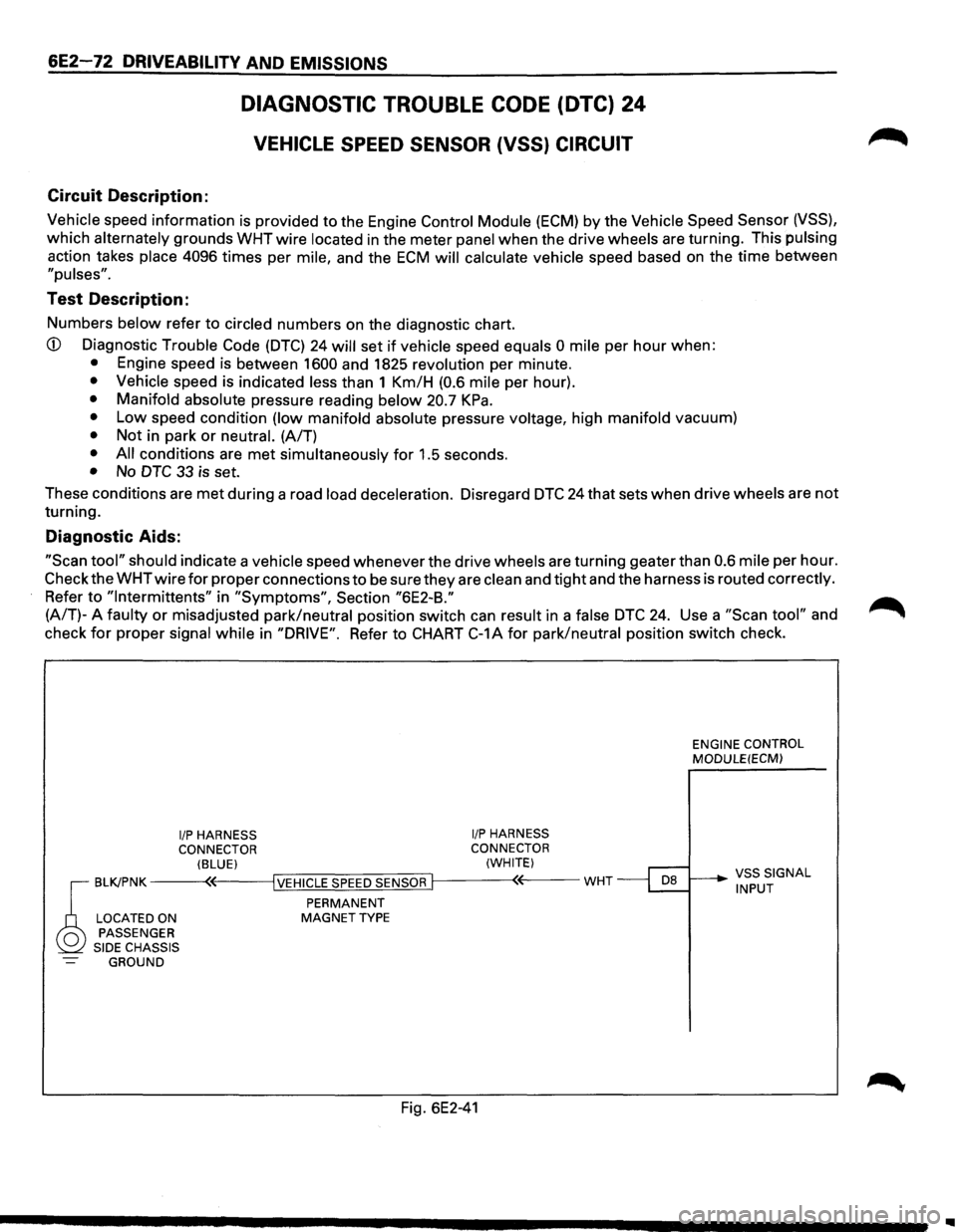
6E2-72 DRIVEABILITV AND EMISSIONS
Circuit Description:
DIAGNOSTIC TROUBLE CODE (DTC) 24
VEHICLE SPEED SENSOR (VSS) CIRCUIT
Vehicle speed information is provided to the Engine Control Module (ECM) by the Vehicle Speed Sensor (VSS),
which alternately grounds WHT wire located in the meter panel when the drive wheels are turning. This pulsing
action takes place 4096 times per mile, and the ECM will calculate vehicle speed based on the time between
"pulses".
Test Description:
Numbers below refer to circled numbers on the diagnostic chart.
CD Diagnostic Trouble Code (DTC) 24 will set if vehicle speed equals 0 mile per hour when:
• Engine speed is between 1600 and 1825 revolution per minute.
• Vehicle speed is indicated less than 1 Km/H (0.6 mile per hour).
• Manifold absolute pressure reading below 20.7 KPa.
• Low speed condition (low manifold absolute pressure voltage, high manifold vacuum)
• Not in park or neutral. (A/T)
• All conditions are met simultaneously for 1.5 seconds.
• No DTC 33 is set.
These conditions are
met during a road load deceleration. Disregard DTC 24 that sets when drive wheels are not
turning.
Diagnostic Aids:
"Scan tool" should indicate a vehicle speed whenever the drive wheels are turning geater than 0.6 mile per hour.
Check the
WHTwire for proper connections to be sure they are clean and tight and the harness is routed correctly.
Refer to "lntermittents" in "Symptoms", Section "6E2-B."
(A/T)- A
faulty or misadjusted park/neutral position switch can result in a false DTC 24. Use a "Scan tool" and
check
for proper signal while in "DRIVE". Refer to CHART C-1A for park/neutral position switch check.
1/P HARNESS 1/P HARNESS CONNECTOR CONNECTOR ENGINE
CONTROL
MODULE(ECM) (BLUE) (WHITE)
BLK/PNK ----<:(-<---{IYJVE~Hi!IQCL~EjS~P~E~ED~S~EN~S~O~RUif-----<~•E---WHT ~ _____. ~~;U~IGNAL
PERMANENT LOCATED ON MAGNET TYPE PASSENGER SIDE CHASSIS
GROUND
Fig. 6E2-41
..