relay ISUZU TROOPER 1995 Workshop Manual
[x] Cancel search | Manufacturer: ISUZU, Model Year: 1995, Model line: TROOPER, Model: ISUZU TROOPER 1995Pages: 1928
Page 1272 of 1928
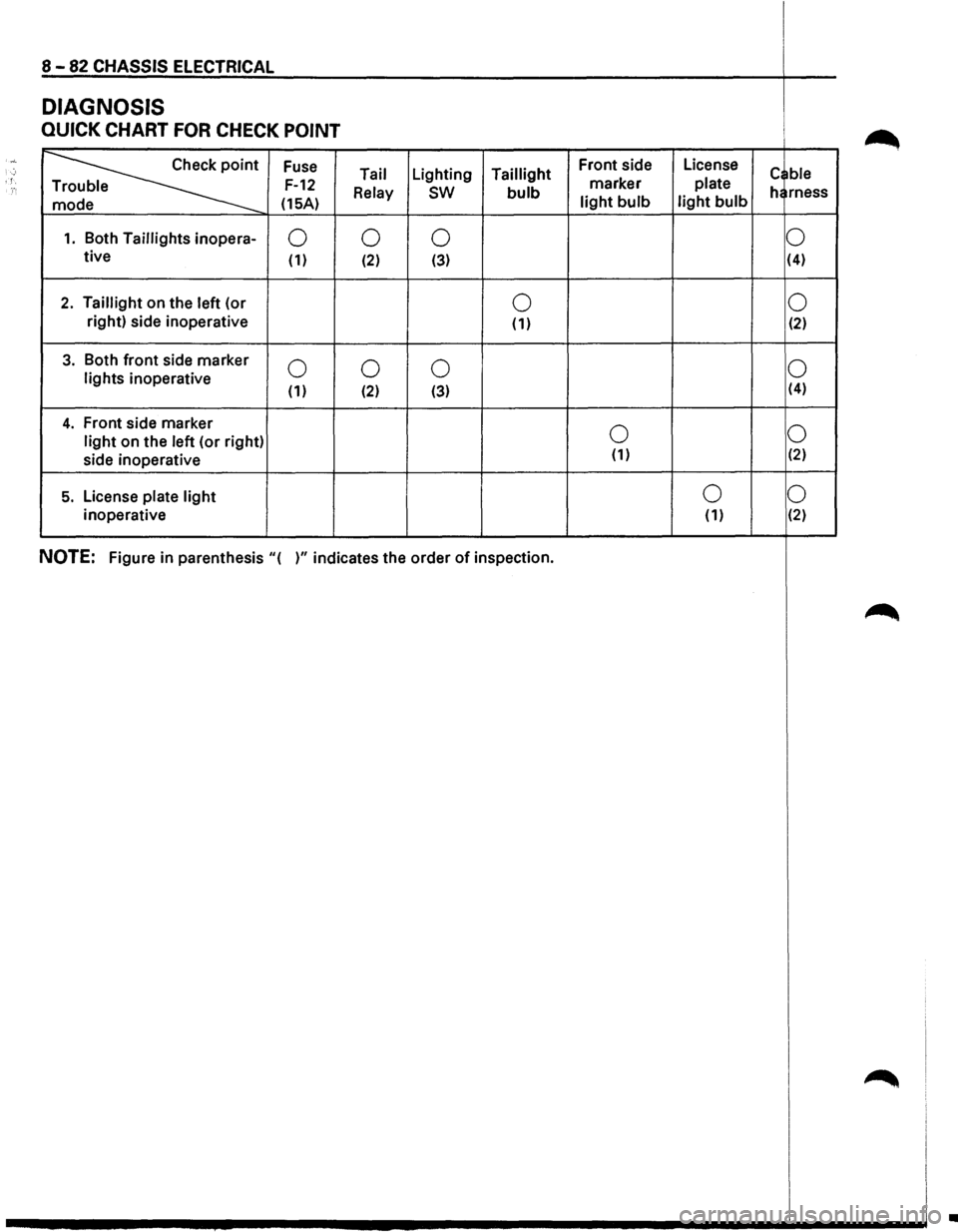
8 -82 CHASSIS ELECTRICAL
DIAGNOSIS
QUICK CHART FOR CHECK POINT
·~··
~
Fuse Front
side License ; Tail Lighting
Taillight
marker plate c ble '. F-12 e
Relay sw bulb he rness
e (15A) light bulb light bulb
1. Both Taillights inopera-0
0
0 0 tive (1) (2) (3) (4)
2. Taillight
on the left (or 0 0 right)
side inoperative
(1) (2)
3. Both front side marker 0 0
0 0 lights inoperative (1) (2) (3) (4)
4. Front
side marker 0 0 light on
the left (or right)
side inoperative (1) (2)
5. License plate light 0
0
inoperative (1) (2)
NOTE: Figure
in parenthesis "( )" indicates the order of inspection.
~
~
•
Page 1273 of 1928
CHASSIS ELECTRICAL 8 -83
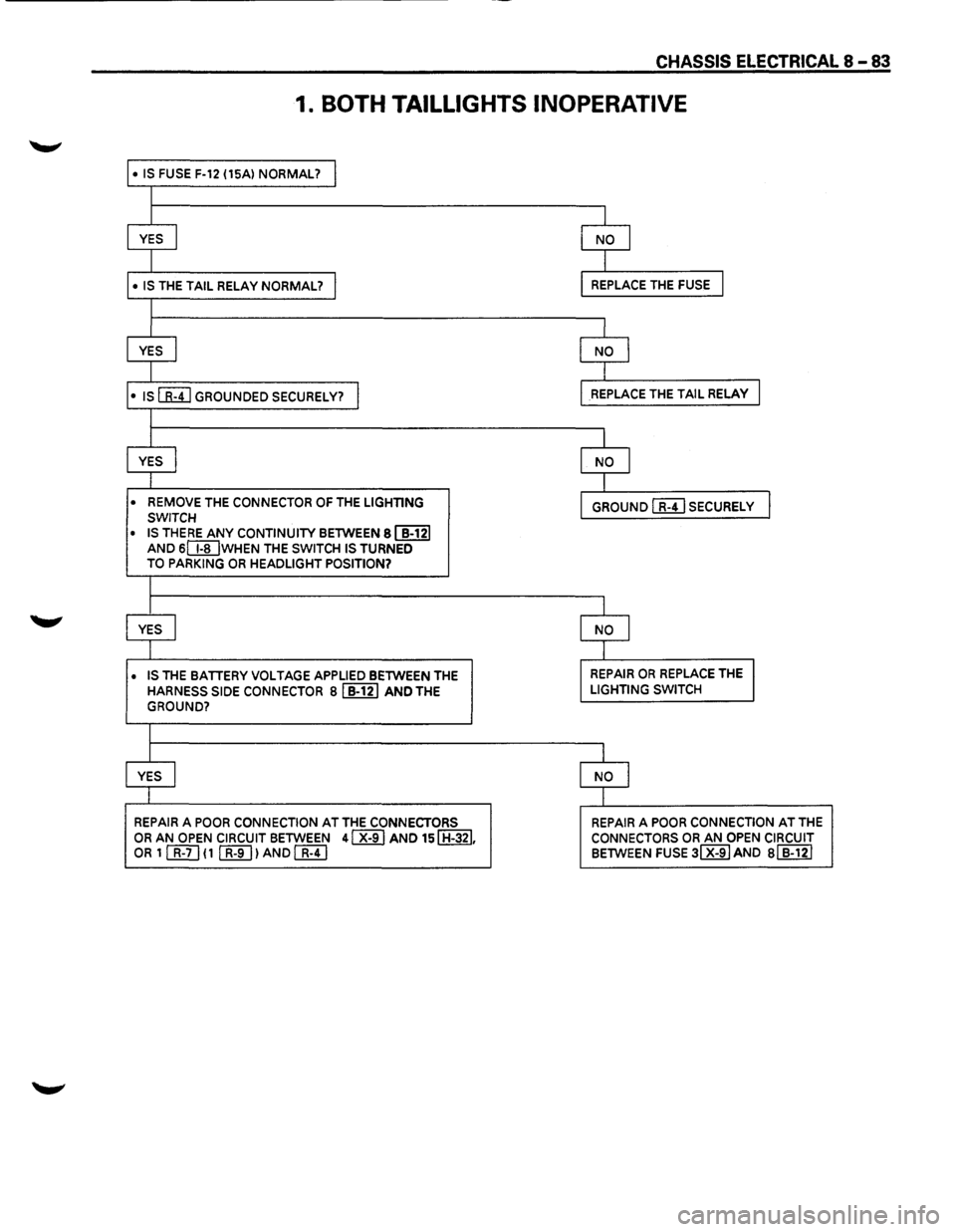
1. BOTH TAILLIGHTS INOPERATIVE
• IS FUSE F-12 (15Al NORMAL? I
I
I
I
YES I NO I
I I
• IS THE TAIL RELAY NORMAL? I REPLACE THE FUSE I
I
I
I
YES I NO I
I I
•
IS[&!] GROUNDED SECURELY? I REPLACE THE TAIL RELAY I
I
I
l
YES I NO I
I I
• REMOVE
THE CONNECTOR OF THE LIGHTING GROUND I R-41 SECURELY I SWITCH
• IS THERE ANY CONTINUITY BETWEEN 81 B-121
AND SIT[] WHEN THE SWITCH IS TURNED
TO PARKING OR HEADLIGHT POSITION?
l
I I
YES I NO I
I I
• IS
THE BATTERY VOLTAGE APPLIED BETWEEN THE REPAIR OR REPLACE THE I
HARNESS SIDE CONNECTOR Bl B-121 AND THE LIGHTING SWITCH
GROUND?
I
I I
YES
I NO I
I I
REPAIR
A POOR CONNECTION AT THE CONNECTORS REPAIR A POOR CONNECTION AT THE
OR AN OPEN CIRCUIT BETWEEN 41 X-91 AND 151 H-321. CONNECTORS OR AN OPEN CIRCUIT OR 1 [friJ ( 1 (K[]) AND[&!] BETWEEN FUSE 31 X-9IAND Bl B-121
Page 1275 of 1928
CHASSIS ELECTRICAL 8-85
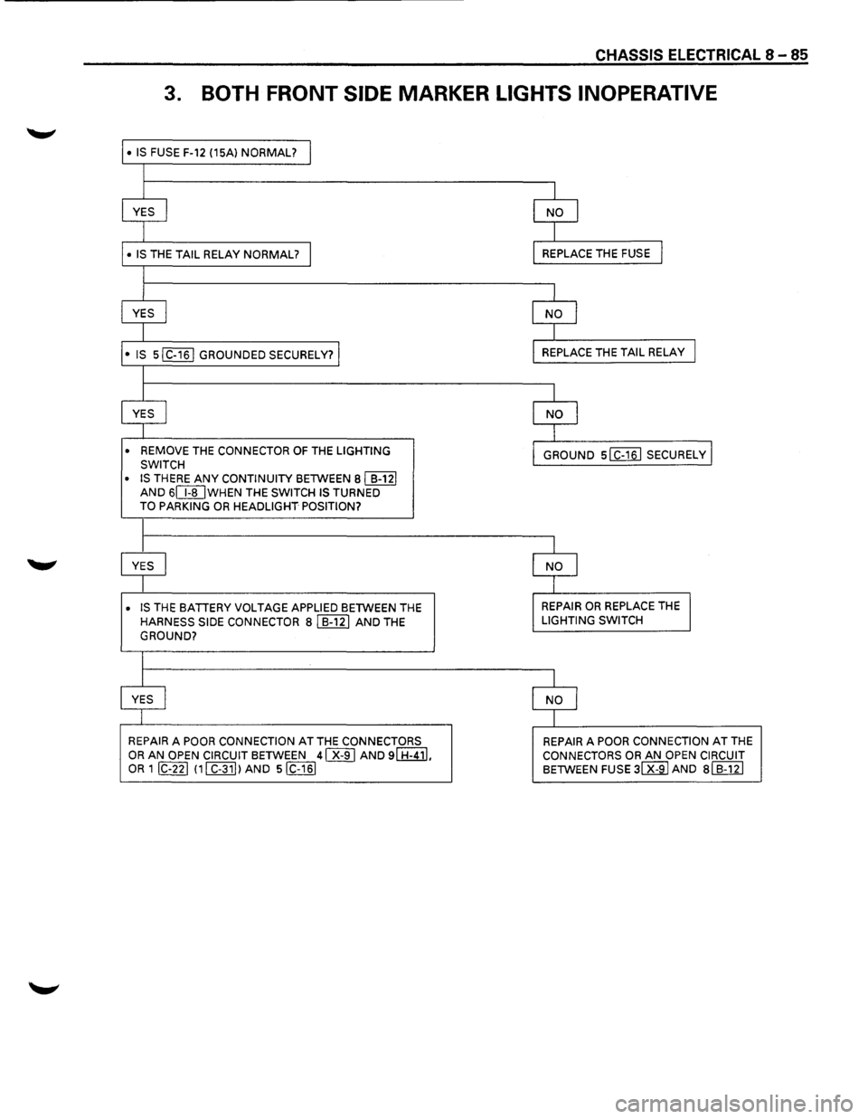
3. BOTH FRONT SIDE MARKER LIGHTS INOPERATIVE
• IS FUSE F-12 (15Al NORMAL? I
l
I I
YES I NO I
I I
• IS THE TAIL RELAY NORMAL? I REPLACE THE FUSE I
l
I I
YES I NO I
I I
• IS sl C-161 GROUNDED SECURELY? I REPLACE THE TAIL RELAY I
I
I
I
YES I NO I
I I
• REMOVE THE CONNECTOR OF THE LIGHTING
GROUND slc-16l SECURELY I SWITCH
• IS
THERE ANY CONTINUITY BETWEEN Bl B-121 AND 6CI[JWHEN THE SWITCH IS TURNED TO PARKING OR HEADLIGHT POSITION?
I
I I
YES I NO I
I I
• IS THE BATTERY VOLTAGE APPLIED BETWEEN THE REPAIR OR REPLACE THE I
HARNESS SIDE CONNECTOR Bl B-121 AND THE LIGHTING SWITCH
GROUND?
I
I
I
YES I NO 1
I I
REPAIR A POOR CONNECTION AT THE CONNECTORS REPAIR A POOR CONNECTION AT THE
OR AN OPEN CIRCUIT BETWEEN 41 X-91 AND 91 H-411, CONNECTORS OR AN OPEN CIRCUIT OR 1 IC-221 111 C-311 lAND siC-161 BETWEEN FUSE 31 X-91 AND al B-121
Page 1280 of 1928
8 -90 CHASSIS ELECTRICAL
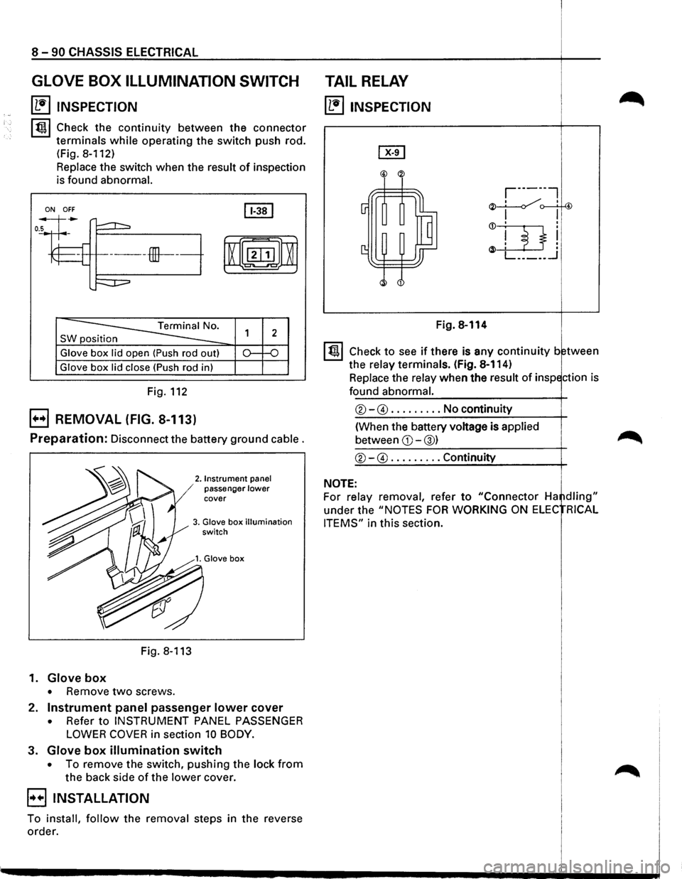
GLOVE BOX ILLUMINATION SWITCH
~ INSPECTION
lt!ll Check the continuity between the connector
terminals
while operating the switch push rod.
(Fig.
8-112)
Replace the switch when the result of inspection
is found
abnormal.
ON OFF
SW position
Glove box lid open (Push rod out)
Glove box lid close (Push rod in)
Fig. 112
EJ REMOVAL (FIG. 8-113)
Preparation: Disconnect the battery ground cable.
2. Instrument panel / passenger lower cover
3. Glove box illumination switch
Fig. 8-113
1.
Glove box
• Remove two screws.
2.
Instrument panel passenger lower cover
• Refer to INSTRUMENT PANEL PASSENGER
LOWER COVER in section 10 BODY.
3. Glove box illumination switch
• To remove the switch, pushing the lock from
the back side of the lower cover.
EIINSTALLATION
To install, follow the removal steps in the reverse
order.
TAIL RELAY
~ INSPECTION
Fig. 8-114
I t!ll Check to see if there is any continuity between
the
relay terminals. (Fig. 8-114)
Replace the
relay when the result of inspection is
found abnormal.
®-@ ......... No continuity
(When the battery voltage is
applied
between CD-@) ~
®-@ ......... Continuity
NOTE:
For relay removal, refer to "Connector Ha ~dling"
under the "NOTES FOR WORKING ON ELEC RICAL
ITEMS"
in this section.
Page 1282 of 1928
I
8 -92 CHASSIS ELECTRICAL I
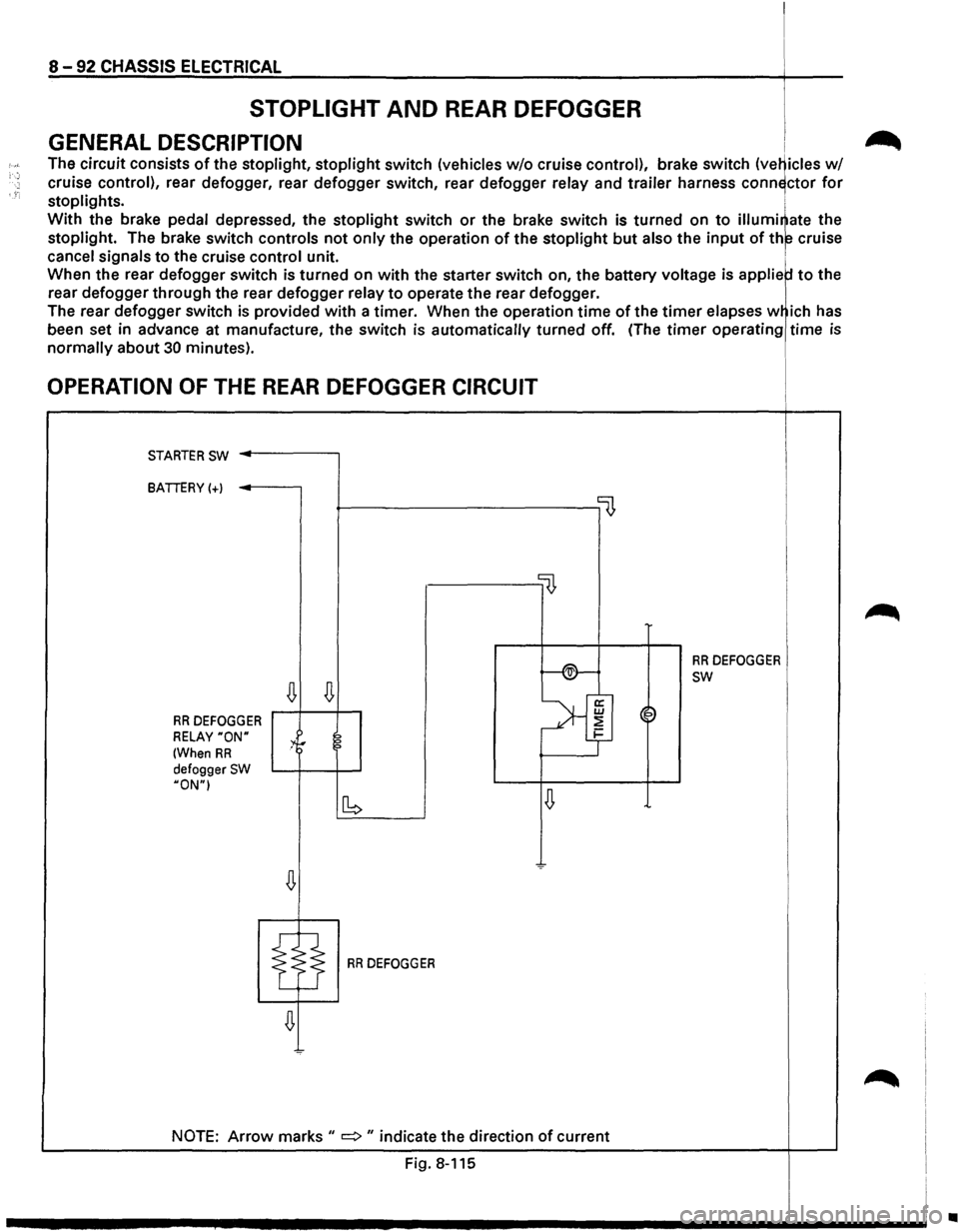
STOPLIGHT AND REAR DEFOGGER I
GENERAL DESCRIPTION i .-_
The circuit consists of the stoplight, stoplight switch (vehicles w/o cruise control), brake switch (ve~icles w/
cruise control), rear defogger, rear defogger switch, rear defogger relay and trailer harness conn~ctor for
stoplights. i
With the brake pedal depressed, the stoplight switch or the brake switch is turned on to illumi~ate the
stoplight. The brake switch controls not only the operation of the stoplight but also the input of th~ cruise
cancel signals to the cruise control unit. 1
When the rear defogger switch is turned on with the starter switch on, the battery voltage is applie to the
rear
defogger through the rear defogger relay to operate the rear defogger.
The rear
defogger switch is provided with a timer. When the operation time of the timer elapses w ich has
been set in advance at manufacture,
the switch is automatically turned off. (The timer operating time is
normally about 30 minutes).
OPERATION OF THE REAR DEFOGGER CIRCUIT
STARTER SW ..------,
BATTERY(+)
~----------------0
llJ,
f-®-
RR DEFOGGER
~
SW
~
>'f RR DEFOGGER ~~
RELAY "ON" :4r 2 1-
(When RR ?
defogger SW HON"I
~ [b
RR DEFOGGER
NOTE: Arrow marks II => II indicate the direction of current
Fig. 8-115
~
•
Page 1283 of 1928
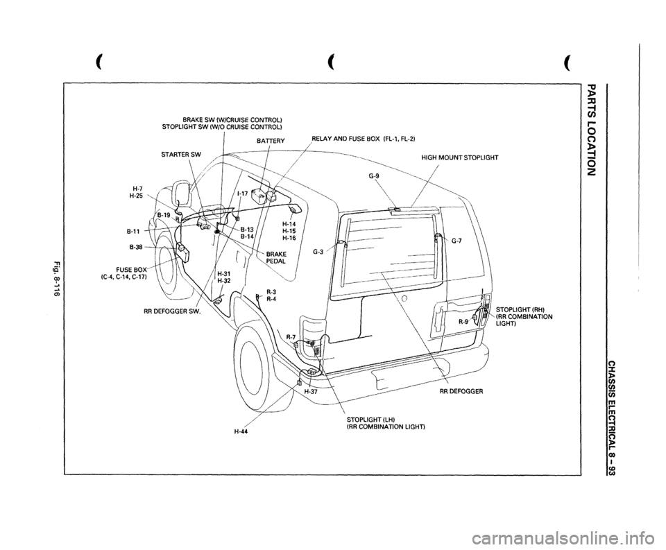
"T1 tO. 00 I _. ... 0>
(
H-7 H-25
,,
B-11
BRAKE
SW
(W/CRUISE
CONTROL)
STOPLIGHT
SW
(W/0
CRUISE
CONTROL) BATTERY
B-38
-
'I ,....., , lUI,).,.
FUSE
sox~
!C-4,
C-14,
C-17l
/
H-44
(
,RELAY
AND
FUSE
BOX
IFL-1,
FL-21
/
~----._
HIGH
MOUNT
STOPLIGHT
~-----
~
G-,~,
~-~------
-~,
I
"~
'
RRDEFOGGER
STOPLIGHT
(LHI
{RR
COMBINATION
LIGHT)
STOPLIGHT
(RHI
(RR
COMBINATION
LIGHT)
(
;g ::xJ ~ r-0 (') ~ -0 2
(') ::t l> en
en en m rm ~ ::Jl ~ Cl) I CD w
Page 1284 of 1928
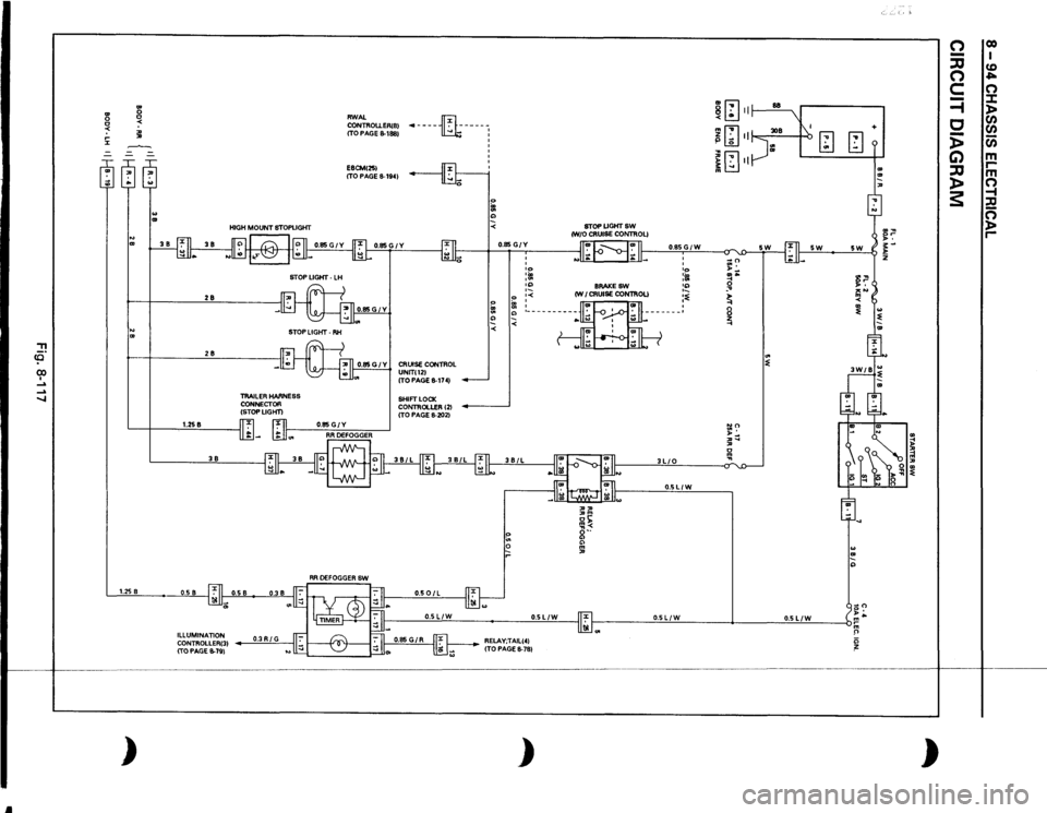
Jl
::!! co (X) I .....
..... ....,
l'l ~ .... J::
.. .. .. .. l'l ~ ~
28 28
STOP LIGHT •
LH
STOP
LIGHT·
RH
TRAILER HARNESS
CONNECTOR
(STOPLIGHT)
RWAL CONTROU.ER(B)
(TO PAGE 8-188)
·-----m:----1
E8CM(25)
(TO
PAGE
8-194)
0.85 G I y I CRUISE CONTROL
UNIT(12) ITO PAGE
8-174)
SHIFT LOCK
CONTROLLER 121
(TO
PAGE
8-202)
0
I
I
1.258
~~~~
r:u
0~~:~------
I
·-
38
1.25
8
0.5 8
0.501L
0.85
GIY :;: 0
I ' IO ... , .. '" ·-
0
•<
~
:
" <
STOPUGHTSW (W/0
CRUISE CONTROL) II
I
I II
8RAKESW
(WI
CRUISE CONTROL) ,, :»m or;;: Ill< o·· " " m ,
I
1-11
0.85GIW 3LIO
'
' •o :m :~ :~
0.5LIW
8
.
ill
-
.. m < .. mm ~ liJ
Ill <::::
-w
I b
[;Jm
I[;Jn ~ § .., :::
5W
"' ~
.. " ..,
II
0.5LIW
•
0.5LIW
11'."1
0.5LIW
I
0.5L/W
b •
Ill -
)
ILLUMINATION CONTROLLER(3) (TO PAGE 8-79)
0.3RIG
RELAY;TAIL(4)
(TO
PAGE 8-78)
)
+ .. .. ,
)
0 -:::0 0 c =i c i> G) :::0 )> s:
00 I CD ""' 0 :I: )> CJ)
CJ) (i) m rm 0 -i :c 0 )> r-
Page 1286 of 1928
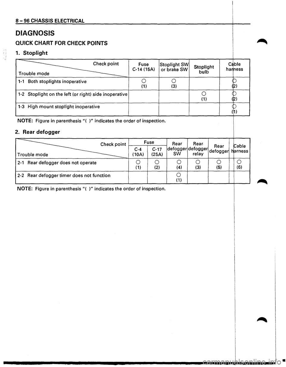
8-96 CHASSIS ELECTRICAL
DIAGNOSIS
QUICK CHART FOR CHECK POINTS
1. Stoplight
~
Fuse Stoplight SW Stoplight c~ ble
C-14 (15A) or brake SW bulb har
ness
Tr
1-1 Both stoplights inoperative 0 0 p
(1) (3) (~)
1-2 Stoplight on the left (or right) side inoperative 0 )
(1) (2)
1-3 High mount stoplight inoperative )
( 1)
NOTE: Figure in parenthesis"( )" indicates the order of inspection.
2. Rear defogger
~·
Fuse
Rear Rear ~able C-4
C-17 defogger defogger Rear
Tr
(10A) (25A) sw relay defogger
harness
2-1 Rear defogger does not operate 0 0 0 0 0
0 ( 1) (2) (4) (3) (5) (6)
2-2 Rear
defogger timer does not function 0 (1)
NOTE: Figure in parenthesis"( )" indicates the order of inspection.
•
Page 1289 of 1928
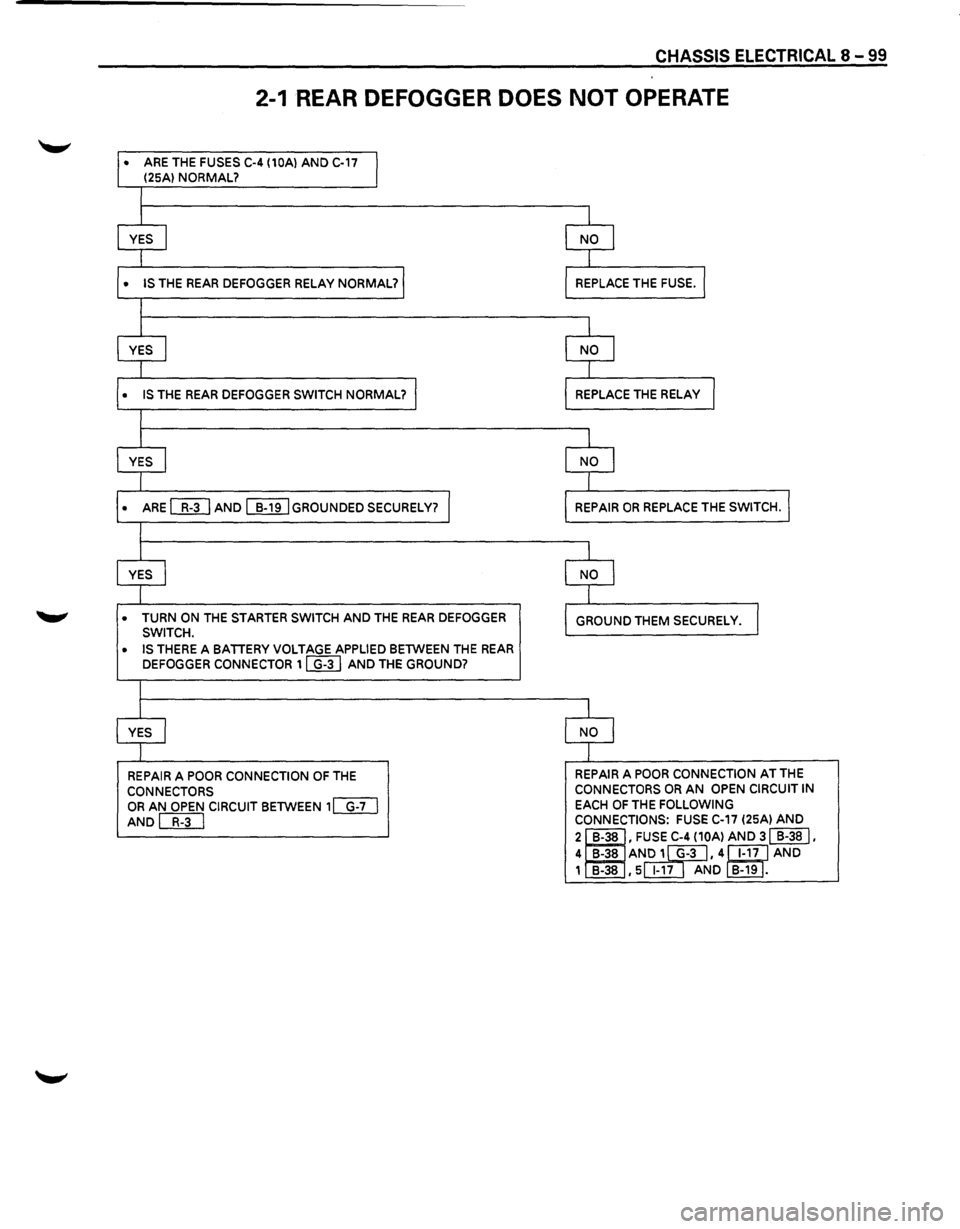
CHASSIS ELECTRICAL 8 -99
2-1 REAR DEFOGGER DOES NOT OPERATE
• ARE THE FUSES C-4 (10Al AND C-17
I (25Al NORMAL?
I
I
YES I NO l
I
• IS THE REAR DEFOGGER RELAY NORMAL? REPLACE THE FUSE. I
I
I
YES I NO I
1
• IS THE REAR DEFOGGER SWITCH NORMAL? I REPLACE THE RELAY I
I
I
YES I NO I
I
• ARE WJ AND ~GROUNDED SECURELY? I REPAIR OR REPLACE THE SWITCH.l
I
I
YES I NO I
I
• TURN ON THE STARTER SWITCH AND THE REAR DEFOGGER
GROUND THEM SECURELY. I SWITCH.
• IS THERE A BATIERY VOLTAGE APPLIED BETWEEN THE REAR DEFOGGER CONNECTOR 1 ~ AND THE GROUND?
I
I
YES I NO l
I
REPAIR A POOR CONNECTION OF THE REPAIR A POOR CONNECTION AT THE
CONNECTORS CONNECTORS OR AN OPEN
CIRCUIT IN
OR AN OPEN CIRCUIT BETWEEN 1[]TI EACH OF THE FOLLOWING
AND[BTI CONNECTIONS: FUSE C-17 (25Al AND
2 I B-38 • FUSE C-4 (10Al AND 31 B-38 I.
4
1B-38 AN~,4~AND 1 ~ , 5 1-17 AND B-19
.
Page 1295 of 1928
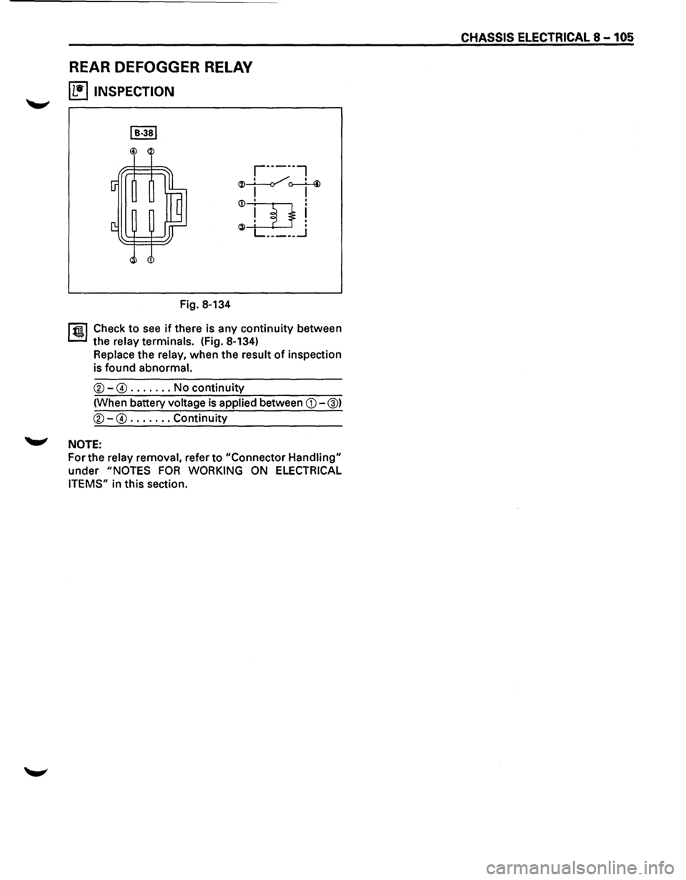
REAR DEFOGGER RELAY
~ INSPECTION
Fig. 8-134
r·-----,
~~o--L-4> I I
1 ~~ Check to see if there is any continuity between
the
relay terminals. (Fig. 8-134)
Replace the relay, when the result of inspection
is found
abnormal.
®-@ ....... No continuity
(When battery
voltage is applied between CD-@)
®-@ ....... Continuity
'-"' NOTE:
For the relay removal, refer to "Connector Handling"
under "NOTES FOR WORKING ON ELECTRICAL
ITEMS"
in this section.
CHASSIS ELECTRICAL 8-105