relay ISUZU TROOPER 1995 Workshop Manual
[x] Cancel search | Manufacturer: ISUZU, Model Year: 1995, Model line: TROOPER, Model: ISUZU TROOPER 1995Pages: 1928
Page 1328 of 1928
8-138 CHASSIS ELECTRICAL
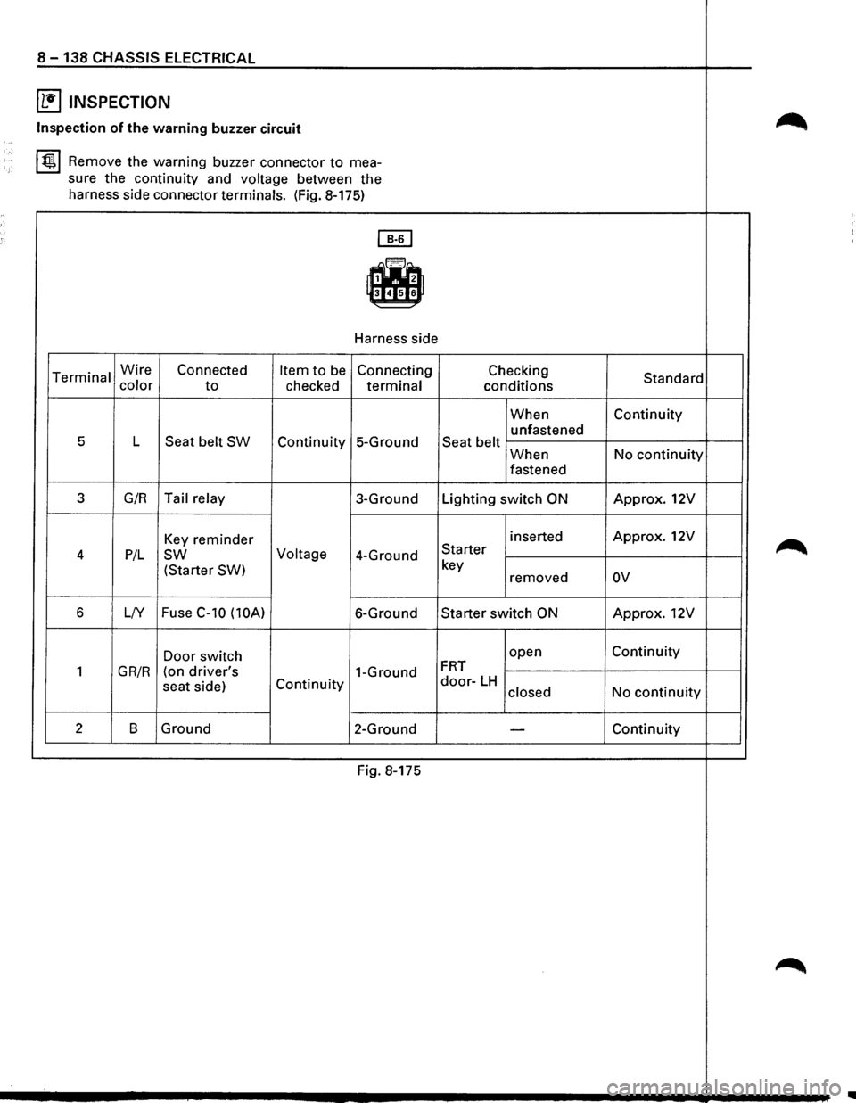
~ INSPECTION
~ Inspection of the warning buzzer circuit ,,,
~ Remove the warning buzzer connector to mea-
sure the continuity and
voltage between the
harness side connector terminals. (Fig. 8-175)
~
-Harness side
Terminal Wire Connected Item to be Connecting Checking Standard color to checked terminal conditions
When Continuity
unfastened
5 L Seat belt SW Continuity 5-Ground Seat belt When No continuity
fastened
3 G/R Tail relay 3-Ground Lighting switch ON Approx. 12V
Key reminder inserted Approx. 12V
~ 4 P/L sw Voltage 4-Ground Starter
(Starter SW)
key
removed ov
6 L/Y Fuse C-10
(lOA) 6-Ground Starter switch ON Approx. 12V
Door switch open Continuity
1 GR/R (on driver's 1-Ground FRT
seat
side) Continuity door-LH No continuity closed
2 B Ground
2-Ground -Continuity
Fig. 8-175
~
Page 1332 of 1928
8-142 CHASSIS ELECTRICAL
POWER DOOR LOCK
GENERAL DESCRIPTION
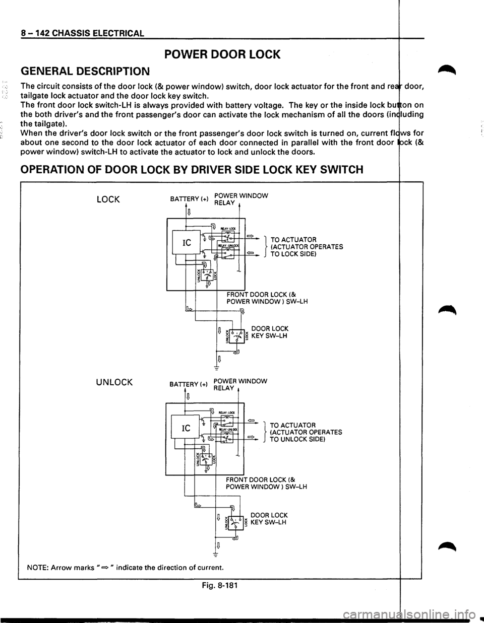
The circuit consists of the door lock (& power window) switch, door lock actuator for the front and rea door,
tailgate
lock actuator and the door lock key switch.
The
front door lock switch-LH is always provided with battery voltage. The key or the inside lock bu on on
the both driver's and the
front passenger's door can activate the lock mechanism of all the doors (in< luding
the tailgate).
When the driver's
door lock switch or the front passenger's door lock switch is turned on, current fie ws for
about one second to the door lock actuator of each door connected in parallel with the front door ock (&
power window) switch-LH to activate the actuator to lock and unlock the doors.
OPERATION OF DOOR LOCK BY DRIVER SIDE LOCK KEY SWITCH
LOCK
UNLOCK
BATTERY(+) POWER WINDOW RELAY
.....-1::::::;---'li) ~
fi ::> ~ = } TO ACTUATOR IC IE~CC (ACTUATOR OPERATES
I l lj~:.-.>+T++==-TO LOCK SIDE)
W=~~~~'l g
Jlf!
FRONT DOOR LOCK (& POWER WINDOW l SW-LH
sb2-f---+---w
U ~rh;±,i DOOR LOCK ~LfJg KEY SW-LH
u =
BATTERY(+) POWER WINDOW RELAY
,..,~T =
I IEl.
CS ~:t-o·++ 1+==-TO UNLOCK SIDE)
IL...t=:t=~~w.~ g
~q;J
FRONT DOOR LOCK (& POWER WINDOW) SW-LH
[b =
U ~8 DOOR LOCK
~l.f} KEY SW-LH
NOTE: Arrow marks"=" indicate the direction of current.
Fig. 8-181
IIIII
Page 1333 of 1928
"T1 !0 (X) I ... (X) N
(
RR
DOOR
LOCK
ACTUATOR
(RHI
DOOR
LOCK
KEY
SW
"-
FRT
DOOR
LOCK
& POWER
WINDOW SW
(RHI
RELAY
& FUSE
BOX (FL-11~
BATTERY
' ,,
( TAILGATE
LOCK
ACTUATOR
(LHI
RR
DOOR
LOCK
ACTUATOR
(LHI
h.=
I //If/:
I
FRT
DOOR
LOCK
& POWER
WINDOW
SW
(LHI
FRT
DOOR
LOCK
ACTUATOR
(LHI
FUSE
BOX
(C-181
(
~ ~ r-0 n ~ 0
2
(") J: )> en
en (i) m rm ~ :a g reo I ...a t
Page 1334 of 1928
8 -144 CHASSIS ELECTRICAL
CIRCUIT DIAGRAM
FL-1 86/R 80AMAIN SW 5W + o---+=-=-4 P-2 ~
GJ
GJ
/
1 H-14 SW
~~P-1ol~ BODY ENG. FRAME 1.25 LG/W
5W
1 C-18 J 20A DOOR LOCK
4 RELAY; POWER WINDOW 141 ITO PAGE 8-1!58)
...
r---D~D~~~1o~------------~~5~7-----,
§*f-----+------+--.51
RE' AY· I I'V'K RELAY; UP 1__;;=.l...v----J--·m~;:;:::::I--·~RELAY; DOWN I ~ ~ ~ 1.25LG IC H-23f----.----------------t--------~
R~LOCK 8 5 ~--r-_)~~i_~t~~~~l~~o~t~--~----~ID-si~~~1-~25~LG~~~~--H~~--~----+---~---4----~--~--~
~!
-
RELAY; UP RELAY; DOWN
D-30JI D-30/1 D-30j ~ 1 2
0 14 2 H-22 H-23
14 2
H-18 H-19
"' BODY-RHij~
3 1
0.5 L!Y
H-19
"' tQ~------------~
"' H-23
"' "' N "' BODY-LH II B-181---------------_J
22 21 H-32 0 -32
3 5 e 3 3 e H-19 H-19
H-34 H-34 H-28 H-28
" .... IQ ~ -' s "' ~ ::!
~ ~ II! s s g s 2
~ IQ
IQ ~ ~ "' IQ H-38 ~ N -' -' -' -'
s ~
"' ;, N ::! "'
Fo.~ Fo-~ Fo-i'f1 Fo-~ ~~ Fo-~ Fo-~ ~2~ Faf1 f. r.1
M M
FAT DOOR LOCK FAT DOOR LOCK ACTUATOA-LH ACTUA TOR-AH
Fig. 8-183
M
ARDOORLOCK ACTUATOR-RH
M
RADOOALOCK ACTUATOA-LH TAILGATE
ACTUATOR· H
•
Page 1341 of 1928
![ISUZU TROOPER 1995 Workshop Manual (b!] INSPECTION OF THE DOOR LOCK
t!l CIRCUIT
~ Check the voltage and the continuity between
the
front door lock (& power window) switch
harness side connector terminals. (Fig. 8-185)
[E)
,](/img/61/57183/w960_57183-1340.png "ISUZU TROOPER 1995 Workshop Manual (b!] INSPECTION OF THE DOOR LOCK
t!l CIRCUIT
~ Check the voltage and the continuity between
the
front door lock (& power window) switch
harness side connector terminals. (Fig. 8-185)
[E)
,")
(b!] INSPECTION OF THE DOOR LOCK
t!l CIRCUIT
~ Check the voltage and the continuity between
the
front door lock (& power window) switch
harness side connector terminals. (Fig. 8-185)
[E)
,, r=1 ,
f.~B
~ slal7lal911o D
TerConnec- minal tor No. Wire
Item to Connecting
color Connected to be
checked terminal
No.
1
7
8
D-5
B
LIB
Ground
Power window
relay
LG/B Lock actuator
(Unlock)
Continuity 1-Ground
Voltage 7-Ground
8-9
CHASSIS ELECTRICAL8 -151
Checking conditions Standard
Continuity
Starter SW
"ON" Approx. 12V
Continuity
9 LG
(There is Continuity 1------.,..--+----------t e
Lock actuator 9-8 -som (Lock) resistance)
10 LG/W Fuse C-18
Voltage 10-Ground Approx.12V
1
(20A)
LG/L Door lock
SW-RH
(Unlock) 1-Ground
Door
lqck SW Unlock Continuity
Lock
No continuity
2 LG/R Door lock 2-Ground Door lock
SW-RH
or
door lock key
SW-LH & RH
Lock Continuity
D-30
3
SW-RH (Lock)
Door lock key
Continuity
SW-LH
& RH
(Lock)
L/Y Door lock key
SW-LH & RH
(Unlock) Unlock
No continuity
3-Ground
Door lock Unlock Continuity
key
SW-LH &
RH Lock No continuity
Fig 8-185
FRONT DOOR LOCK (& POWER
WINDOW) SWITCH-LH
The front door lock (&power window) switch sends
out to each door lock actuator the lock/unlock signals
received
from both door lock switch and door lock
key switch.
Fig 8-186
Page 1346 of 1928
8 -156 CHASSIS ELECTRICAL
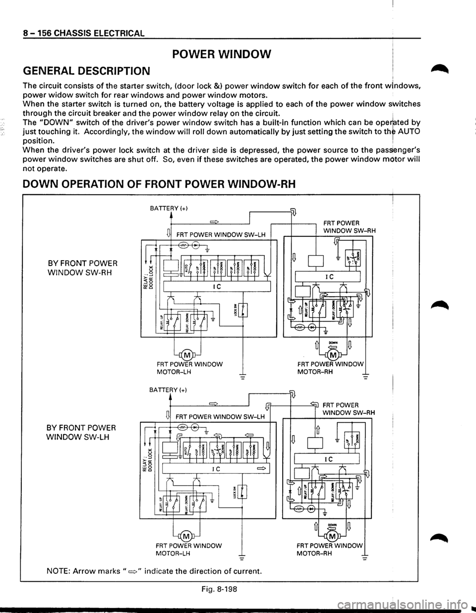
POWER WINDOW
GENERAL DESCRIPTION I
The circuit consists of the starter switch, (door lock &) power window switch for each of the front wlndows,
power widow switch for rear windows and power window motors.
When the starter switch is
turned on, the battery voltage is applied to each of the power window switches
through the circuit breaker and the power window relay on the circuit. ,
The "DOWN" switch of the driver's power window switch has a built-in function which can be ope~ted by
just.t?uching it. Accordingly, the window will roll down automatically by just setting the switch to thf AUTO
pos1t1on. ,
When the driver's power lock switch at the driver side is depressed, the power source to the pas~enger's
power window switches are shut off. So, even if these switches are operated, the power window motor will
not operate.
DOWN OPERATION OF FRONT POWER WINDOW-RH
BY FRONT POWER
WINDOW SW-RH
BATTERY(+)
D FRT POWER WINDOW SW-LH
FRT POWER WINDOW MOTOR-LH
BATTERY(+) .------'li)
FRT POWER WINDOW MOTOR-RH
1]1'------+------'"itl
BY FRONT POWER
WINDOW SW-LH
D FAT POWER WINDOW SW-LH
FAT POWER WINDOW MOTOR-LH
NOTE: Arrow marks "=>" indicate the direction of current.
Fig.
8-198
FRT POWER WINDOW MOTOR-RH
..
Page 1347 of 1928
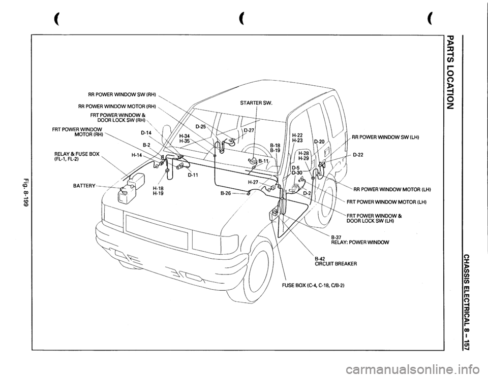
"T1 <0" 0) I ..... CD
CD
(
RR
POWER
WINDOW SW
(RH)
~
RR
POWER
WINDOW
MOTOR
(RH)
,
FRT
POWER
WINDOW
&
DOOR
LOCK
SW
(RH)
FRT
POWER
WINDOW MOTOR(RH)
RELAY
& FUSE
BOX
~
(FL-1,
FL-2)
~
BATTERY~
-,
(
"-
(
RR
POWER
WINDOW SW
(LH)
D-22 RR
POWER
WINDOW
MOTOR
(LH)
B-42
B-37
' FRT
POWER
WINDOW
MOTOR
(LH)
'FRT
POWER
WINDOW
&
DOOR
LOCK
SW
(LH)
RELAY:
POWER
WINDOW
CIRCUIT
BREAKER
~ :JJ -1 C/) r-0 0 ;; 0 2
n :X: )> 0
0 c;; m ,.. m ~ ::u c; )> ,.. co I ..,a ~
Page 1348 of 1928
,-,·
8 -158 CHASSIS ELECTRICAL
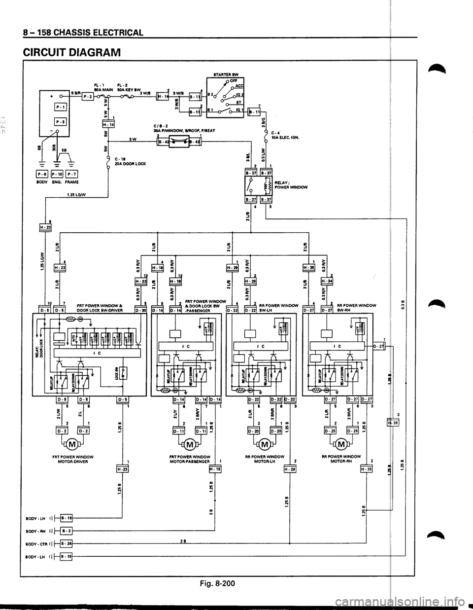
CIRCUIT DIAGRAM
8TARTERSW
FL-1 FL-2
-II
.-----, S Bill 80A MAIN lOA KEY IW o--t---1 P. 2 ~ -<>"" 3 W/1
B .. !!:
+
"' I fP7 ~ H-14 C/1-2 1i .. ~ 30A P/WINDOW, I/IIOOF, P/IEAT
~---~3W~--~~~--------~
~
~ C-4· lOA ELEC. IGN.
"' ci i
., Iii 58
--~
E!JIP-Iol(!3 BODY ENG. FRAME
i ..
~F:d IB-37IIB-37
I p ] RELAY; I I 9 J POWER WINDOW
C-18 20A DOOR LOCK
1.25 LG/W
4 3 ~~~-37
~ N ~----------------------------~--,
~ 4 ~ I ~
~ .. .. ~
~-2~ :·It ra :·2t ~-28
a FRT POWER WINDOW ~ 1= ~ 1=~ FRT POWER WINDOW I< 1= ~ ~ I< DOOR LOCK SW d l=lJ, RR POWER WINDOW
r-'-1..;;. oor-s"'" '"'"' 1 oo,-..;;. 55.__ I_;;;.Do'"'o"'R..;;.Lo;..;CK=.;sw.;..-OR=.;IV..;;.ER'---.o;; 1oo., --~30 o-141 -PASSENGER o-221 ID -221 sw-LH
~ ~-~~~i~ II ~" ~ ~" ~
i§ I I c IO ~ ~
~ ~ •J ~~h ~r~ lrt=H•
i~~ I[ . ~~~ iL4J_ il~
... ..
2 I
D-2 D-2
M
FRT POWER WINDOW MOTOR-DRIVER
H-23
Ill
s
BODY· LH II B • IBf---------___J
~g,-~ ~g,-~~~ e 1 1
~ i N N
D-11
M
I Ill Ill D-11 ,..:
FRT POWER WINDOW MOTOR-PASSENGER I
Ill N
-19
BODY-RH II r-8f---------------------------------....l'
,-!-
.
~ 5 ~~ e r=3
~ ~ N Ill N 2 I Ill
D-20 0-20 l(l ,..:
M
FIR POWER WINDOW
MOTOII-LH 2
H
-29
I ~ H-35 .. ci
!:
:~ lM·-·~· D-27 BW-RH
~ 1~ I
I C H-s-
lo ~ -A
!~ ~ i[~t
~ v
~ s ~~~ 6 3 ~ ~ Ill .. N ~ 2 I Ill l(l D-25 D-25 ,..:
M
I RR POWER WINDOW MOTOR-RH 2
1
H -35
Ill :e ,..:
BODY-CTR II 8-261---------------------------'2'-"8'---------------------------+-------\
-----------'
Ill .. 0
3
35
Ill l(l ,..:
BODY-LH lj B • 19f---------------------------------------------------------------------\
--------it---'
Fig. 8-200
~
~
Page 1350 of 1928
8-160 CHASSIS ELECTRICAL
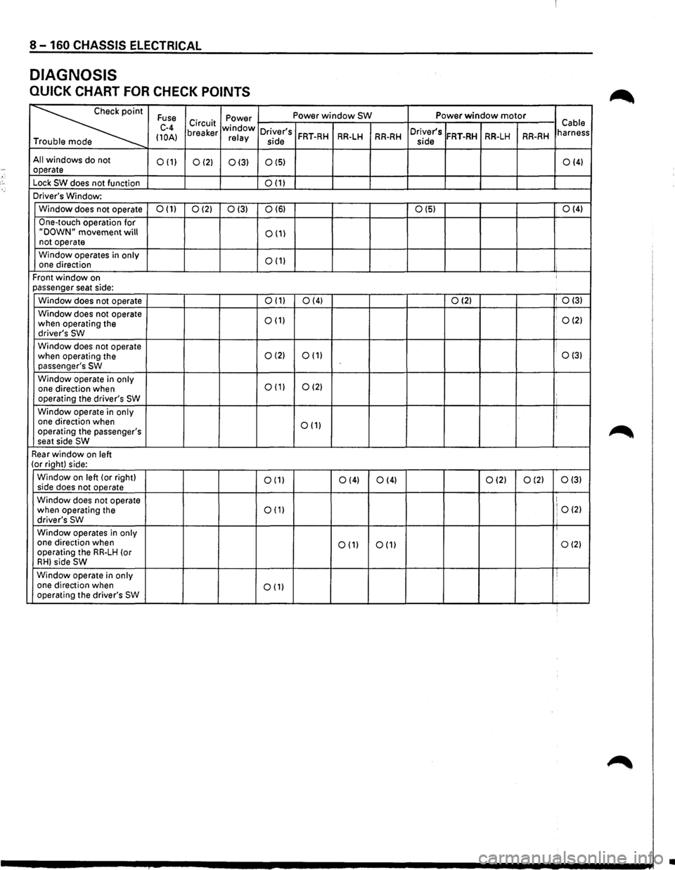
DIAGNOSIS
QUICK CHART FOR CHECK POINTS
~
Fuse Power Power window SW Power window motor
C-4 Circuit window Cable
(10A) breaker relay Driver's FRT-RH RR-LH RR-RH Driver's FRT-RH RR-LH RR-RH harness
T side
side
All windows do not 0(1) 0(2) 0(3) 0(5) 0(4) operate
Lock
SW does not function 0(1)
Driver's Window:
Window does not operate
0(1) 0(2) 0(3) 0(6) 0(5) 0(4)
One-touch
operation for "DOWN" movement will 0(1) not operate
Window operates in
only 0(1) one direction
Front
window on ' passenger seat side:
Window does not operate
0(1) 0(4) 0(2) I 0(3)
Window
does not operate 0(1) . 0(2) when operating the
driver's SW
Window does not operate
when operating the 0(2) 0(1) 0(3) passenger's SW
Window operate in only 0(1) 0(2) one direction when
operating the driver's SW
Window operate in only I one direction when 0(1) operating the passenger's
seat side SW
Rear window on left (or right) side:
Window
on left (or right) 0(1) 0(4) side
does not operate 0(4) 0(2) 0(2) 0(3)
Window does not operate ! 0(2) when operating the 0(1) driver's SW ' Window operates in only one direction when
operating the RR-LH (or 0(1) 0(1) 0(2)
RH) side SW
Window
operate in only i one direction when 0(1) operating the driver's SW
•
Page 1351 of 1928
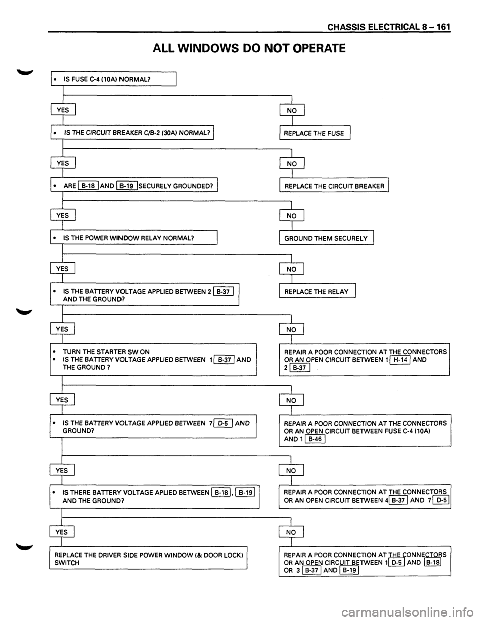
CHASSIS ELECTRICAL 8-161
ALL WINDOWS DO NOT OPERATE
• IS FUSE C-4 (10A) NORMAL? I
I
YES I NO I
I
• IS THE CIRCUIT BREAKER C/B-2 (30Al NORMAL? I REPLACE THE FUSE I
I
YES I NO I
I
• ARE ~AND I B-19 !sECURELY GROUNDED? J REPLACE THE CIRCUIT BREAKER I
I
YES I NO I
I
• IS THE POWER WINDOW RELAY NORMAL? I GROUND THEM SECURELY I
I
YES I NO I
I
• IS THE BATTERY VOLTAGE APPLIED BETWEEN 21 B-37 I J REPLACE THE RELAy I AND THE GROUND?
I
YES I NO
I
I
• TURN THE STARTER SW ON REPAIR A POOR CONNECTION AT THE CONNECTORS
• IS THE BATTERY VOLTAGE APPLIED BETWEEN 11 B-371 AND OR AN OPEN CIRCUIT BETWEEN 1 CB:BJ AND THE GROUND? 2IB-37I
I
YES j NO I
I
• IS THE BATTERY VOLTAGE APPLIED BETWEEN 7[@ AND REPAIR A POOR CONNECTION AT THE CONNECTORS
GROUND? OR AN OPEN CIRCUIT BETWEEN FUSE C-4 (10A)
AND 11 B-461
I
YES I NO J
I
• IS THERE
BATTERY VOLTAGE APLIED BETWEEN I B-1sl,l B-191 REPAIR A POOR CONNECTION AT THE CONNECTORS
AND THE GROUND? OR AN OPEN
CIRCUIT BETWEEN 41 B-371 AND 71 D-51
I
YES I NO I
I
REPLACE THE DRIVER SIDE POWER WINDOW I& DOOR LOCK) 1 SWITCH REPAIR A POOR CONNECTION AT IHE TONNiCTOiS OR AN OPEN
CIRCUIT BETWEEN 1 D-5 AND B-18
OR sl B-371 AND I B-191