ISUZU TROOPER 1995 Workshop Manual
Manufacturer: ISUZU, Model Year: 1995, Model line: TROOPER, Model: ISUZU TROOPER 1995Pages: 1928
Page 1691 of 1928
STEP
1
2
3
4 5
6
7 8
Suppl~mental Restraint System 9J·67
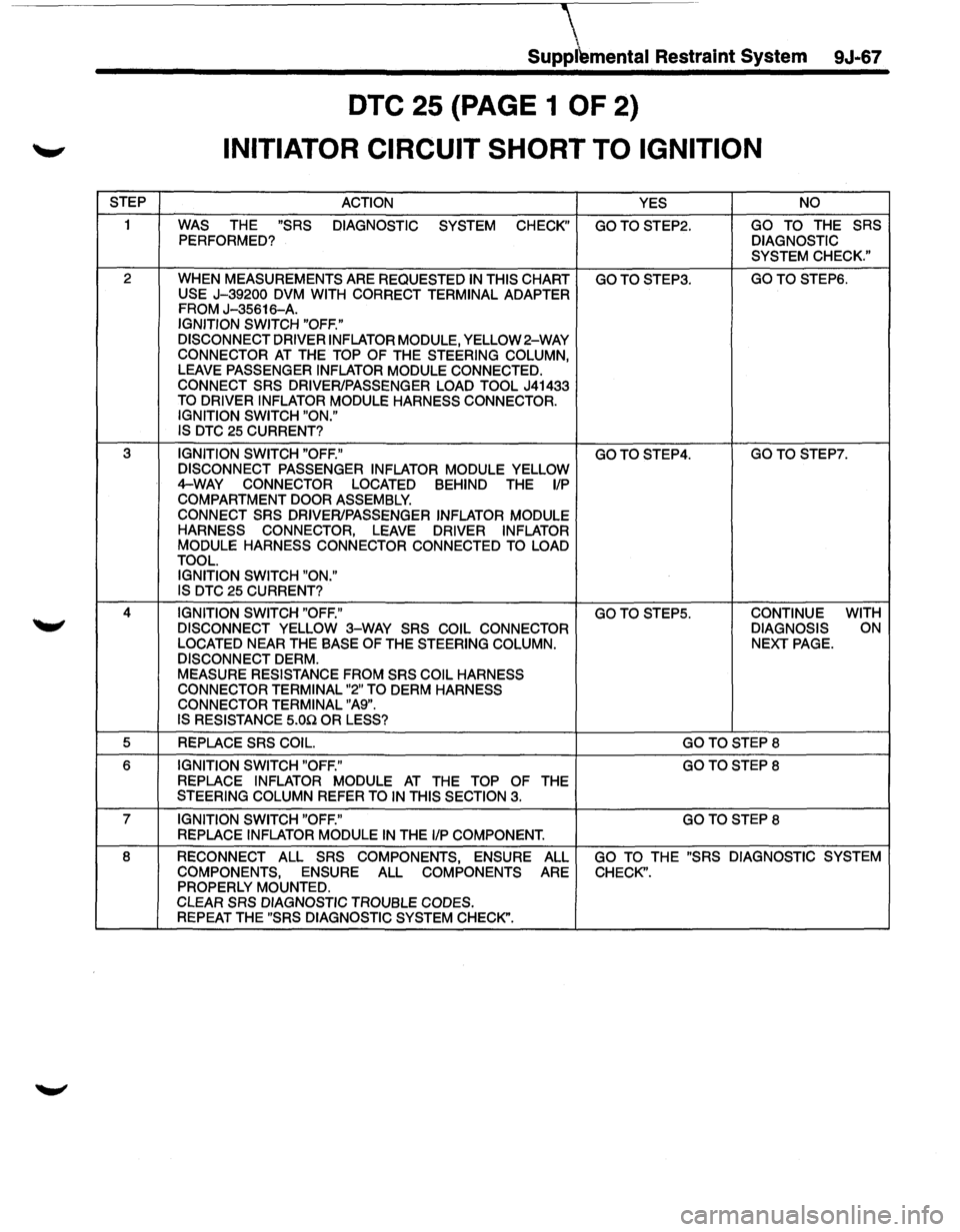
DTC 25 (PAGE 1 OF 2)
INITIATOR CIRCUIT SHORT TO IGNITION
ACTION
YES NO
WAS
THE "SRS DIAGNOSTIC SYSTEM CHECK" GOTOSTEP2. GO TO THE SRS PERFORMED? DIAGNOSTIC
SYSTEM CHECK."
WHEN MEASUREMENTS ARE REQUESTED IN THIS CHART GOTOSTEP3. GOTO STEPS.
USE J-39200 DVM WITH CORRECT TERMINAL ADAPTER FROM J-35616-A. IGNITION SWITCH "OFF."
DISCONNECT DRIVER INFLATOR
MODULE, YELLOW 2-WAY CONNECTOR AT THE TOP OF THE STEERING COLUMN, LEAVE PASSENGER INFLATOR MODULE CONNECTED.
CONNECT SRS DRIVER/PASSENGER LOAD TOOL J41433 TO DRIVER INFLATOR MODULE HARNESS CONNECTOR.
IGNITION SWITCH "ON."
IS DTC
25 CURRENT?
IGNITION SWITCH "OFF." GOTOSTEP4. GOTOSTEP7. DISCONNECT PASSENGER INFLATOR MODULE YELLOW 4-WAY CONNECTOR
LOCATED BEHIND THE 1/P COMPARTMENT DOOR ASSEMBLY.
CONNECT SRS DRIVER/PASSENGER INFLATOR
MODULE HARNESS CONNECTOR, LEAVE DRIVER INFLATOR MODULE HARNESS
CONNECTOR CONNECTED TO LOAD
TOOL.
IGNITION SWITCH "ON."
IS DTC
25 CURRENT?
IGNITION SWITCH "OFF." GOTO STEP5. CONTINUE
WITH
DISCONNECT YELLOW 3-WAY SRS COIL CONNECTOR DIAGNOSIS ON
LOCATED
NEAR THE BASE OF THE STEERING COLUMN. NEXT PAGE.
DISCONNECT DERM. MEASURE RESISTANCE FROM SRS COIL HARNESS
CONNECTOR TERMINAL "2" TO DERM HARNESS
CONNECTOR TERMINAL "A9".
IS RESISTANCE 5.00 OR LESS?
REPLACE SRS COIL. GOTOSTEP8
IGNITION SWITCH "OFF." GOTOSTEP8
REPLACE INFLATOR MODULE AT THE TOP OF THE STEERING COLUMN REFER TO IN THIS SECTION 3.
IGNITION SWITCH "OFF." GOTOSTEP8
REPLACE INFLATOR MODULE IN THE 1/P COMPONENT.
RECONNECT
ALL SRS COMPONENTS, ENSURE ALL GO TO THE "SRS DIAGNOSTIC SYSTEM
COMPONENTS, ENSURE
ALL COMPONENTS ARE CHECK". PROPERLY MOUNTED.
CLEAR SRS DIAGNOSTIC TROUBLE CODES. REPEAT THE "SRS DIAGNOSTIC SYSTEM CHECK".
Page 1692 of 1928
9J-68 Supplemental Restraint System
DTC 25 {PAGE 2 OF 2)
INITIATOR CIRCUIT SHORT TO IGNITION
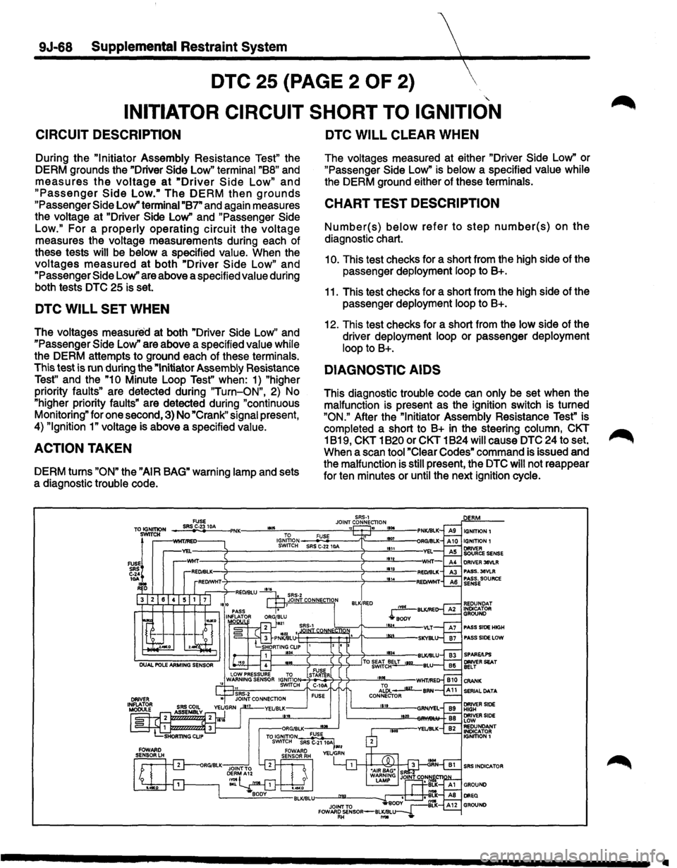
CIRCUIT DESCRIPTION
During the "Initiator Assembly Resistance Test" the
DERM grounds the "Driver
Side Low" terminal "88" and
measures the voltage at "Driver Side Low" and
"Passenger Side Low." The DERM then grounds
"Passenger Side Low" terminai"B7" and again measures
the voltage at "Driver
Side Low" and "Passenger Side
Low." For a properly operating circuit the voltage
measures the voltage measurements during each of
these tests
will be below a specified value. When the
voltages measured at both "Driver Side Low" and
"Passenger Side Low" are above a specified value during
both tests DTC 25 is set.
DTC WILL SET WHEN
The voltages measured at both "Driver Side Low" and
"Passenger Side Low" are above a specified value while
the DERM attempts to ground each of these terminals.
This test is run during the
"Initiator Assembly Resistance
Test" and the "10 Minute Loop Test'' when: 1) "higher
priority faults" are detected during
"Turn-ON", 2) No
"higher priority
faults" are detected during "continuous
Monitoring" for one second, 3) No
"Crank" signal present,
4)
"Ignition 1" voltage is above a specified value.
ACTION TAKEN
DERM turns "ON" the "AIR BAG" warning lamp and sets
a diagnostic trouble code.
....
DTC WILL CLEAR WHEN
The voltages measured at either "Driver Side Low" or
"Passenger Side Low" is below a specified value while
the DERM ground either of these terminals.
CHART TEST DESCRIPTION
Number(s) below refer to step number(s) on the
diagnostic chart.
1
0. This test checks for a short from the high side of the
passenger deployment loop to 8+.
11. This test checks for a short from the high side of the
passenger deployment loop to 8+.
12. This test checks for a short from the low side of the
driver deployment loop or passenger deployment
loop to B+.
DIAGNOSTIC AIDS
This diagnostic trouble code can only be set when the
malfunction is present as the ignition switch is turned
"ON." After the "Initiator Assembly Resistance Test" is
completed a short to B+ in the steering column, CKT
1819, CKT 1820 or CKT 1824
will cause DTC 24 to set.
When a scan tool "Clear Codes" command is issued and
the malfunction is
still present, the DTC will not reappear
for ten minutes or until the next ignition cycle.
SRS-1 JOINT CONNECTlON ,l 10 1101 ERM
PASS.3eVLR PASS. SOURCE SENSE
PASS SIDe HIGH PASS SIDe LOW
SERIAL DATA
SRS INDICA TOR
II
Page 1693 of 1928
Supplemental Restrai~t System 9J-69
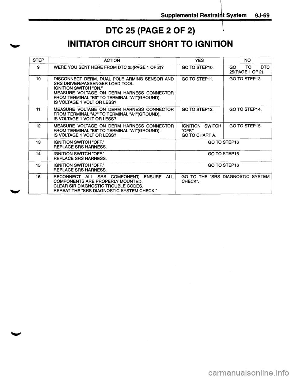
DTC 25 {PAGE 2 OF 2)
INITIATOR CIRCUIT SHORT TO IGNITION
STEP ACTION YES NO
9 WERE YOU SENT HERE FROM DTC 25(PAGE 1 OF 2)? GO TO STEP1 0. GO TO DTC
25(PAGE 1
OF 2).
10 DISCONNECT DERM, DUAL POLE ARMING SENSOR AND GO TO STEP11. GO TO STEP13.
SRS DRIVER/PASSENGER LOAD TOOL.
IGNITION SWITCH "ON."
MEASURE VOLTAGE ON DERM HARNESS CONNECTOR
FROM TERMINAL "89" TO TERMINAL
"A1"(GROUND).
IS
VOLTAGE 1 VOLT OR LESS?
11 MEASURE VOLTAGE ON DERM HARNESS CONNECTOR GO TO STEP12. GO TO STEP14.
FROM
TERMINAL "A7" TO TERMINAL "A1"(GROUND). IS VOLTAGE 1 VOLT OR LESS?
12
MEASURE VOLTAGE ON DERM HARNESS CONNECTOR IGNITION SWITCH GO
TO STEP15.
FROM
TERMINAL "88" TO TERMINAL "A1"(GROUND). "OFF."
IS VOLTAGE 1 VOLT OR LESS? GO TO CHART A.
13 IGNITION SWITCH "OFF." GOTO STEP16
REPLACE
SRS HARNESS.
14
IGNITION SWITCH "OFF." GOTO STEP16
REPLACE
SRS HARNESS.
15
IGNITION SWITCH "OFF." GO TO STEP16
REPLACE SRS HARNESS.
16 RECONNECT ALL
SRS COMPONENT, ENSURE ALL GO TO THE "SRS DIAGNOSTIC SYSTEM
COMPONENTS
ARE PROPERLY MOUNTED. CHECK". CLEAR SIR DIAGNOSTIC TROUBLE CODES. REPEAT THE "SRS DIAGNOSTIC SYSTEM CHECK."
Page 1694 of 1928
9J-70 Supplemental Restraint System
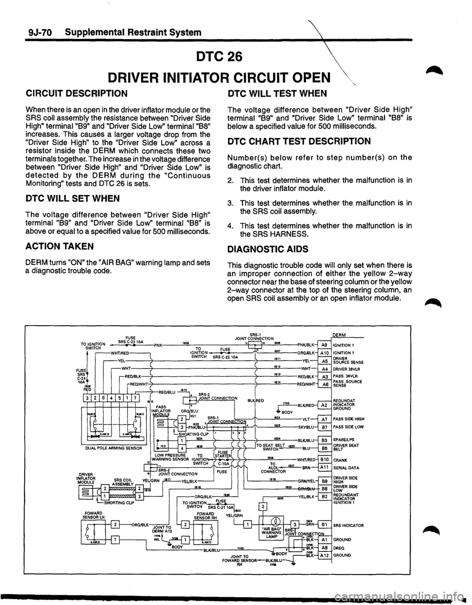
DTC26
DRIVER INITIATOR CIRCUIT OPEN
CIRCUIT DESCRIPTION
When there is an open in the driver inflator module or the
SRS coil assembly the resistance between "Driver Side
High" terminal "89" and "Driver Side Low" terminal "88"
increases. This causes a larger voltage drop from the
"Driver
Side High" to the "Driver Side Low" across a
resistor inside the DERM which connects these two
terminals together. The increase in the voltage difference
between "Driver
Side High" and "Driver Side Low" is
detected by the DERM during the "Continuous
Monitoring" tests and DTC 26 is sets.
DTC WILL SET WHEN
The voltage difference between "Driver Side High"
terminal "89" and "Driver Side Low" terminal "88" is
above or
equal to a specified value for 500 milliseconds.
ACTION TAKEN
DERM turns "ON" the "AIR BAG" warning lamp and sets
a diagnostic
trouble code.
TO IGNITION FUSE SRS C-23 lOA , ...
DTC WILL TEST WHEN
The voltage difference between "Driver Side High"
terminal "89" and "Driver Side Low" terminal "88" is
below a specified value for 500 milliseconds.
DTC CHART TEST DESCRIPTION
Number(s) below refer to step number(s) on the
diagnostic chart.
2. This test determines whether the malfunction is in
the driver inflator module.
3. This test determines whether the malfunction is in
the SRS coil assembly.
4. This test determines whether the malfunction is in
the SRS HARNESS.
DIAGNOSTIC AIDS
This diagnostic trouble code will only set when there is
an improper connection of either the
yellow 2-way
connector near the base of steering column or the yellow
2-way connector at the top of the steering column, an
open SRS coil assembly or an open inflator module.
SRS·l
JOINT CONNECTION ,.,. IGNITION 1 SWITCH
FUSE~
1GrJ;~ION--
I----'18"'34'----T---7-3--7-+---'"11134..._-BLI
DRIVER 36VLR PASS. 36VLR PASS. SOURCE SENSE
REDUNDAT INDICATOR GROUND
PASS SIDE HIGH
PASS SIDE LOW
SERIAL DATA
DRIVER SIDE HIGH DRIVER SlOE LOW REDUNDANT INDICATOR IGNITION 1
SRS INDICATOR
Ill
Page 1695 of 1928
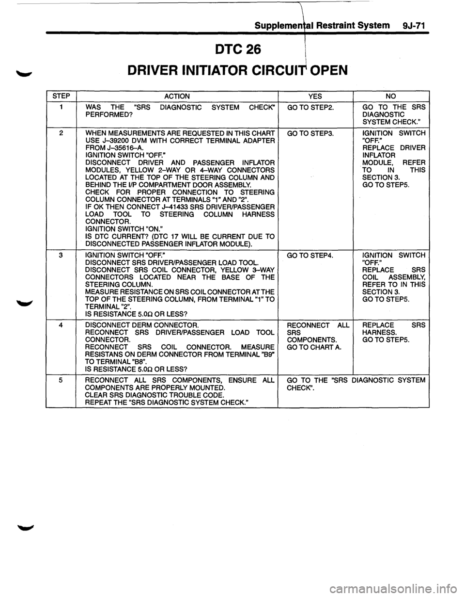
STEP
1
2
3
4
5
Supplemetl Restraint System 9J-71
DTC 26 l
I
DRIVER INITIATOR CIRCUIT OPEN
ACTION
YES
WAS THE "SRS DIAGNOSTIC SYSTEM CHECK" GO TO STEP2.
PERFORMED?
WHEN MEASUREMENTS ARE REQUESTED
IN THIS CHART GO TO STEP3. USE J-39200 DVM WITH CORRECT TERMINAL ADAPTER
FROM J-35616-A.
IGNITION SWITCH "OFF."
DISCONNECT DRIVER
AND PASSENGER INFLATOR
MODULES,
YELLOW 2-WAY OR 4-WAY CONNECTORS
LOCATED AT THE TOP OF THE STEERING COLUMN AND BEHIND THE 1/P COMPARTMENT DOOR ASSEMBLY. CHECK FOR PROPER CONNECTION TO STEERING
COLUMN CONNECTOR AT TERMINALS "1" AND "2". IF OK THEN CONNECT J-41433 SRS DRIVER/PASSENGER
LOAD TOOL TO STEERING COLUMN HARNESS
CONNECTOR.
IGNITION SWITCH "ON."
IS
DTC CURRENT? (DTC 17 WILL BE CURRENT DUE TO
DISCONNECTED PASSENGER INFLATOR
MODULE).
IGNITION SWITCH "OFF." GO TO STEP4. DISCONNECT SRS DRIVER/PASSENGER LOAD TOOL.
DISCONNECT SRS COIL CONNECTOR, YELLOW 3-WAY CONNECTORS LOCATED NEAR THE BASE OF THE STEERING COLUMN. MEASURE RESISTANCE ON SRS COIL CONNECTOR AT THE TOP OF THE STEERING COLUMN, FROM TERMINAL "1" TO
TERMINAL "2". IS RESISTANCE 5.00 OR LESS?
DISCONNECT
DERM CONNECTOR.
RECONNECT SRS DRIVER/PASSENGER LOAD TOOL
CONNECTOR.
RECONNECT SRS COIL CONNECTOR.
MEASURE RESISTANS ON DERM CONNECTOR FROM TERMINAL "B9" TO TERMINAL "B8". IS RESISTANCE 5.00 OR LESS? RECONNECT
ALL SRS COMPONENTS. GO TO
CHART A.
NO
GO TO THE SRS
DIAGNOSTIC SYSTEM CHECK."
IGNITION SWITCH
"OFF." REPLACE DRIVER
INFLATOR
MODULE, REFER TO IN THIS
SECTION 3.
GOTOSTEP5.
IGNITION SWITCH
"OFF." REPLACE SRS
COIL
ASSEMBLY, REFER TO IN THIS
SECTION 3. GO TO STEPS.
REPLACE SRS
HARNESS. GOTOSTEPS.
RECONNECT
ALL SRS COMPONENTS, ENSURE ALL COMPONENTS ARE PROPERLY MOUNTED. GO TO THE "SRS DIAGNOSTIC SYSTEM
CHECK".
CLEAR SRS DIAGNOSTIC
TROUBLE CODE. REPEAT THE "SRS DIAGNOSTIC SYSTEM CHECK."
Page 1696 of 1928
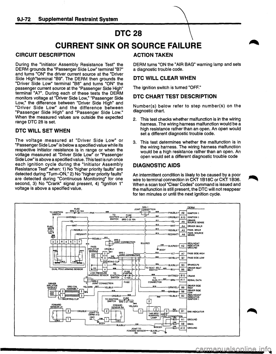
9J-72 Supplemental Restraint System
DTC28
CURRENT SINK OR SOURCE FAILURE
CIRCUIT DESCRIPTION
During the "Initiator Assembly Resistance Test" the
DERM grounds the "Passenger Side Low" terminal
"87"
and turns "ON" the driver current source at
the "Driver
Side High"terminal "89". The DERM then grounds the
"Driver Side Low" terminal
"88" and turns "ON" the
passenger current source at the "Passenger Side High"
terminal "A7". During each of these tests the DERM
monitors voltage at "Driver Side Low," "Passenger Side
Low," the difference between "Driver Side High" and
"Driver Side Low" and the difference between
"Passenger Side High" and "Passenger Side Low."
When the measured values are outside the expected
range DTC 28 is set.
DTC WILL SET WHEN
The voltage measured at "Driver Side Low" or
"Passenger Side Low'' is below a specified value while its
respective initiator resistance is
in range or when the
voltage measured at "Driver Side
Low" or "Passenger
Side Low" is above a specified value. This test is
run once
each
ignition cycle during the "Initiator Assembly
Resistance Tesf' when: 1) No "higher priority faults" are
detected during
"Turn-oN," 2) No "higher priority faults"
are detected during "Continuous Monitoring" for one
second, 3) No
"Crank" signal present, 4) "Ignition 1"
voltage is above a specified value.
, ...
ACTION TAKEN
DERM turns "ON the "AIR BAG" warning lamp and sets
a diagnostic trouble code.
DTC WILL CLEAR WHEN
The ignition switch is turned "OFF."
DTC CHART TEST DESCRIPTION
Number(s) below refer to step number(s) on the
diagnostic chart.
2. This test checks whether malfunction is in the wiring
harness. The wiring harness malfunction would be a
high resistance rather than an open. An open would
set a different diagnostic trouble code.
3. This test determines whether the malfunction is in
the wiring harness. The wiring harness malfunction
would be a high resistance rather than an open.
An
open would set a different diagnostic trouble code
DIAGNOSTIC AIDS
An intermittent condition is likely to be caused by a poor
wire to terminal connection
in CKT 1 B18C or CKT 1836.
When a scan tool
"Clear Codes" command is issued and
the malfunction is still present, the DTC will not reappear
for ten minutes or until the next ignition cycle.
SRS-1 JOINT CONNECTION 10 11508
IGJ~oN-_;F,:::U:;SE~--t\:__-!!£'"'L-SWITCH SRS C-22 10A 11511 1812 181l
Bl RED
IIIII
Page 1697 of 1928
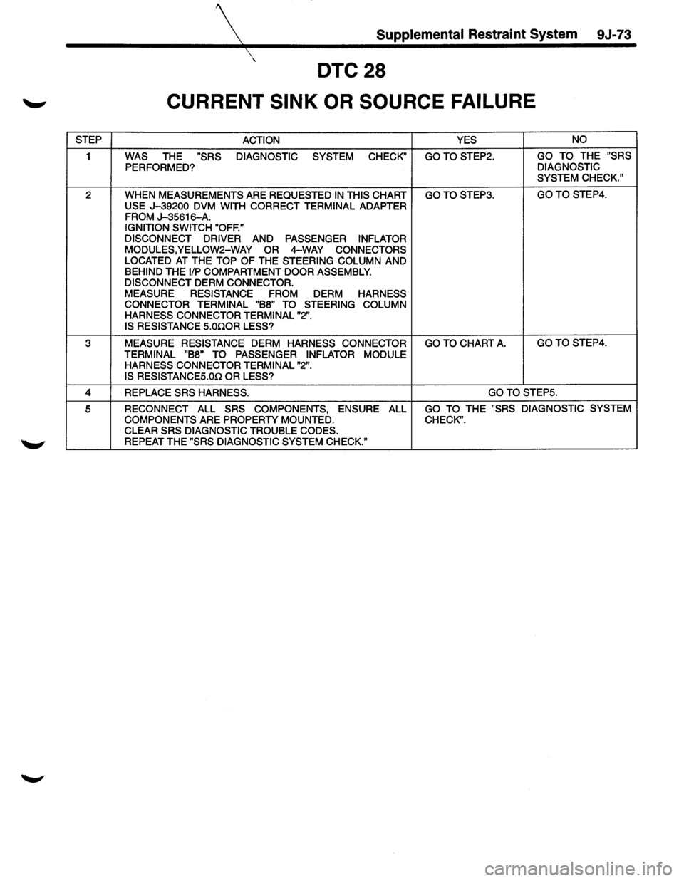
Supplemental Restraint System 9J-73
DTC28
CURRENT SINK OR SOURCE FAILURE
STEP
ACTION YES NO
1 WAS THE "SRS
DIAGNOSTIC
SYSTEM
CHECK" GOTOSTEP2. GO TO THE "SRS
PERFORMED? DIAGNOSTIC
SYSTEM CHECK."
2
WHEN MEASUREMENTS ARE REQUESTED IN THIS CHART GOTOSTEP3. GOTO STEP4.
USE
J-39200 DVM WITH CORRECT TERMINAL ADAPTER FROM J-35616-A. IGNITION SWITCH "OFF."
DISCONNECT DRIVER AND PASSENGER INFLATOR
MODULES,YELLOW2-WAY OR 4-WAY CONNECTORS
LOCATED AT THE TOP OF THE STEERING COLUMN AND
BEHIND THE 1/P COMPARTMENT DOOR ASSEMBLY.
DISCONNECT DERM CONNECTOR.
MEASURE RESISTANCE FROM
DERM HARNESS
CONNECTOR TERMINAL "B8" TO STEERING COLUMN
HARNESS CONNECTOR TERMINAL "2".
IS RESISTANCE S.OnOR LESS?
3 MEASURE RESISTANCE DERM HARNESS CONNECTOR GO TO CHART A. GOTOSTEP4.
TERMINAL "B8" TO PASSENGER INFLATOR MODULE
HARNESS CONNECTOR TERMINAL "2".
IS RESISTANCES.On OR LESS?
4 REPLACE SRS HARNESS. GOTO STEPS.
5 RECONNECT ALL SRS COMPONENTS, ENSURE ALL GO TO THE "SRS DIAGNOSTIC SYSTEM
COMPONENTS
ARE PROPERTY MOUNTED. CHECK". CLEAR SRS DIAGNOSTIC TROUBLE CODES.
REPEAT THE "SRS DIAGNOSTIC SYSTEM CHECK."
Page 1698 of 1928

9J-74 Supplemental Restraint System
---~
DTC31 \"'
DRIVER LOOP ENERGY RESERVE FEED OPEN
CIRCUIT DESCRIPTION
During the "Continuous Monitoring" tests the DERM
monitors the
voltage at "Driver Source Sense" terminal
"AS." When the circuit is operating normally the
measured voltage will be slightly less than "Driver 36
VLR."
If the "Driver 36 VLR" circuit opens the voltage
measured at "Driver Source Sense" will decrease to
slightly less than "Ignition 1" voltage. When the voltage
measured at "Driver Source Sense" is within a specified
range of
"Ignition 1" for SOO milliseconds DTC 31 is set.
DTC WILL SET WHEN
The voltage measured at "Driver Source Sense" terminal
"AS"
is within a specified range of "Ignition 1" for SOO
milliseconds. This test is run every 100 milliseconds
during "Continuous Monitoring" tests.
ACTION TAKEN
DERM turns "ON" the "AIR BAG" warning lamps and sets
a diagnostic
trouble code.
DTC WILL CLEAR WHEN
The voltage measured at "Driver Source Sense" terminal
"AS"
is outside the specified range of "Ignition 1" which
sets the diagnostic
trouble code, for SOO milliseconds.
TO IGNITION SWITCH
FUSE! SRS C-24 lOA , ... R D
FUSE SRS C-23 IDA , ...
DTC CHART TEST DESCRIPTION
Number(s) below refer to step number(s) on the
diagnostic chart.
2. This test checks for an open in the "Driver 36VLR"
circuit.
3. This test checks for a high resistance, but not an
open, in the "Driver Source Sense" circuit.
4. This test checks for a short from the "Driver Source
Sense" circuit to 8+.
s. This test determines whether the malfunction is due
to the
dual pole arming sensor.
DIAGNOSTIC AIDS
An intermittent condition is likely to be caused by a poor
connection at arming sensor
terminal "4" or "6", poor
connection at DERM
terminal "A4" or "AS", an open in
CKT 1811 or CKT 1812, or an open inside the dual pole
arming sensor.
IGNITION1
IGNITION1
DRIVER SOURCE SENSE DRIVER 38VLR PASS.3eVLR PASS. SOURCE SENSE
PASS SIDE HIGH
PASS SIDE LOW
SPARE/LPS
SERIAL DATA
SRS INDICATOR
..
Page 1699 of 1928
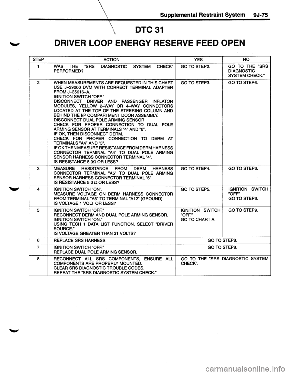
Supplemental Restraint System 9J-75
DTC31
DRIVER LOOP ENERGY RESERVE FEED OPEN
STEP ACTION YES NO
1 WAS THE "SRS
DIAGNOSTIC SYSTEM CHECK'' GOTOSTEP2. GO TO THE "SRS
PERFORMED? DIAGNOSTIC
SYSTEM CHECK."
2
WHEN MEASUREMENTS ARE REQUESTED IN THIS CHART GOTOSTEP3. GOTOSTEP6.
USE J-39200 DVM WITH CORRECT TERMINAL ADAPTER FROM J-35616-A.
IGNITION SWITCH "OFF."
DISCONNECT DRIVER AND PASSENGER INFLATOR
MODULES, YELLOW 2-WAY OR 4-WAY CONNECTORS
LOCATED AT THE TOP OF THE STEERING COLUMN AND BEHIND THE 1/P COMPARTMENT DOOR ASSEMBLY. DISCONNECT DUAL POLE ARMING SENSOR.
CHECK FOR PROPER CONNECTION TO DUAL POLE
ARMING SENSOR AT TERMINALS "4" AND "6".
IF OK, THEN DISCONNECT DERM. CHECK
FOR PROPER CONNECTION
TO DERM AT TERMINALS "A4" AND "5".
IF OK
THEN MEASURE RESISTANCE FROM DERM HARNESS
CONNECTOR TERMINAL "A4" TO DUAL POLE ARMING
SENSOR HARNESS CONNECTOR TERMINAL "4". IS RESISTANCE 5.00 OR LESS?
3 MEASURE RESISTANCE FROM DERM HARNESS GOTOSTEP4. GOTOSTEP6.
CONNECTOR TERMINAL "A5" TO DUAL POLE ARMING
SENSOR HARNESS CONNECTOR TERMINAL "6"
IS RESISTANCE 5.0 Q OR LESS?
4 IGNITION SWITCH "ON". GOTOSTEP5. IGNITION SWITCH
MEASURE VOLTAGE ON DERM HARNESS CONNECTOR "OFF"
FROM TERMINAL "A5" TO TERMINAL "A12" (GROUND). GOTO STEPS.
IS VOLTAGE 1 VOLT OR LESS?
5 IGNITION SWITCH "OFF." IGNITION
SWITCH GOTO STEPS.
RECONNECT
DERM AND DUAL POLE ARMING SENSOR. "OFF."
IGNITION SWITCH "ON." GO TO CHART A. USING TECH 1 DATA LIST FUNCTION, SELECT "DRIVER
SOURCE." IS VOLTAGE
GREATER THAN 31 VOLTS?
6 REPLACE SRS HARNESS. GOTOSTEP8.
7 IGNITION SWITCH "OFF." GOTOSTEP8.
REPLACE DUAL POLE ARMING SENSOR.
8 RECONNECT ALL SRS COMPONENTS, ENSURE ALL GO TO THE "SRS DIAGNOSTIC SYSTEM
COMPONENTS
ARE PROPERLY MOUNTED. CHECK".
CLEAR SRS DIAGNOSTIC TROUBLE CODES.
REPEAT THE "SRS DIAGNOSTIC SYSTEM CHECK."
Page 1700 of 1928
9J-76 Supplemental Restraint System
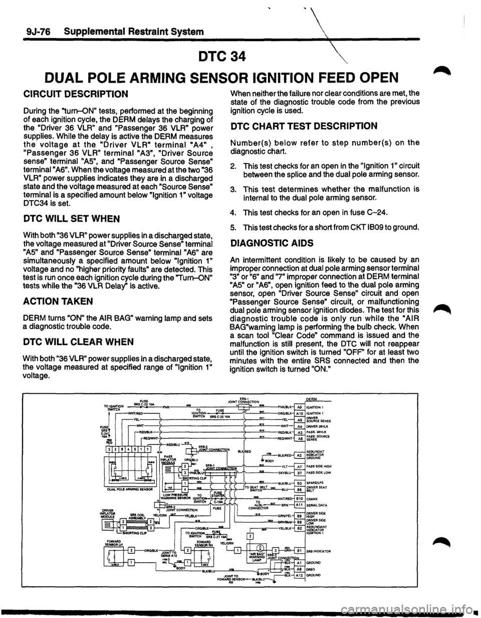
DTC34
DUAL POLE ARMING SENSOR IGNITION FEED OPEN
CIRCUIT DESCRIPTION
During the "turn-ON" tests, performed at the beginning
of each ignition cycle, the DERM delays the charging of
the
"Driver 36 VLR" and "Passenger 36 VLR" power
supplies.
While the delay is active the DERM measures
the voltage at the "Driver VLR" terminal "A4" ,
"Passenger 36 VLR" terminal "A3", "Driver Source
sense" terminal "AS", and "Passenger Source Sense"
terminal "A6". When the voltage measured at the two "36
VLR" power supplies indicates they are in a discharged
state and the voltage measured at each
"Source Sense"
terminal is a specified amount below "Ignition 1" voltage
DTC34 is set.
DTC WILL SET WHEN
With both "36 VLR" power supplies in a discharged state,
the voltage measured at "Driver
Source Sense" terminal
"AS" and "Passenger Source Sense" terminal "A6" are
simultaneously a specified amount below
"Ignition 1"
voltage and no "higher priority faults" are detected. This
test is run once each ignition cycle during the "Turn-ON"
tests while the "36
VLR Delay" is active.
ACTION TAKEN
DERM turns "ON" the AIR BAG" warning lamp and sets
a diagnostic trouble code.
DTC WILL CLEAR WHEN
With both "36 VLR" power supplies in a discharged state,
the voltage measured at specified range of
"Ignition 1"
voltage. When
neither the failure nor clear conditions are met, the
state of the diagnostic trouble code from the previous
ignition cycle is used.
DTC CHART TEST DESCRIPTION
Number(s) below refer to step number(s) on the
diagnostic chart.
2. This test checks for an open in the "Ignition 1" circuit
between the
splice and the dual pole arming sensor.
3. This test determines whether the malfunction is
internal to the dual pole arming sensor.
4. This test checks for an open in fuse C-24.
s. This test checks for a short from CKT 1809 to ground.
DIAGNOSTIC AIDS
An intermittent condition is likely to be caused by an
improper connection at dual pole arming sensor terminal
"3" or "6" and "7" improper connection at DERM terminal
"AS" or "A6", open ignition feed to the dual pole arming
sensor, open "Driver
Source Sense" circuit and open
"Passenger
Source Sense" circuit, or malfunctioning
dual pole arming sensor ignition diodes. The test for this
diagnostic trouble code is only run while the "AIR
BAG"warning lamp is performing the bulb check. When
a scan tool "Clear Code" command is issued and the
malfunction
is still present, the DTC will not reappear
until the ignition switch is turned
"OFP' for at least two
minutes with the entire
SRS connected and then the
ignition switch is turned
"ON."
Ill