headlights ISUZU TROOPER 1995 Workshop Manual
[x] Cancel search | Manufacturer: ISUZU, Model Year: 1995, Model line: TROOPER, Model: ISUZU TROOPER 1995Pages: 1928
Page 501 of 1928
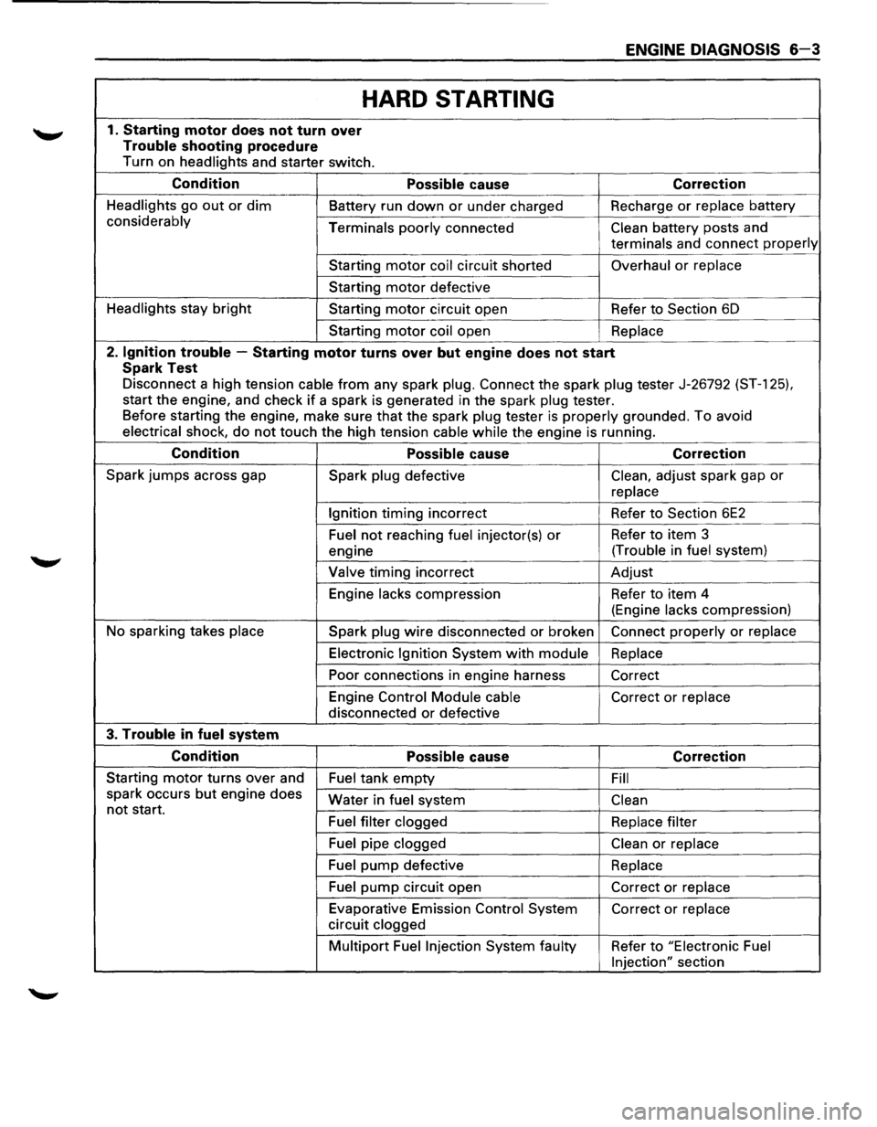
ENGINE DIAGNOSIS 6-3
HARD STARTING
1. Starting motor does not turn over
Trouble shooting procedure
Turn on headlights and starter switch.
Condition Possible cause Correction
Headlights go out or dim Battery run down or under charged Recharge or replace battery
considerably
Terminals poorly connected Clean battery posts and
terminals and connect properly
Starting motor coil circuit shorted Overhaul or replace
Starting motor defective
Headlights stay
bright Starting motor circuit open Refer to Section 6D
Starting
motor coil open Replace
2. Ignition trouble -Starting motor turns over but engine does not start
Spark Test
Disconnect a high tension cable from any spark plug. Connect the spark plug tester J-26792 (ST-1 25).
start the engine, and check if a spark is generated in the spark plug tester.
Before starting the engine, make sure
that the spark plug tester is properly grounded. To avoid
electrical shock, do not touch the high tension cable while the engine is running.
Condition Possible cause Correction
Spark jumps across gap
Spark plug defective Clean, adjust spark gap or
replace
Ignition
timing incorrect Refer to Section 6E2
Fuel not reaching fuel injector(s) or Refer to item 3
engine (Trouble
in
fuel system)
Valve
timing incorrect Adjust
Engine
lacks compression Refer to item 4
(Engine
lacks compression)
No sparking takes
place Spark plug wire disconnected or broken Connect properly or replace
Electronic Ignition System with module Replace
Poor connections in engine harness
Correct
Engine Control
Module cable Correct or replace
disconnected or defective
3. Trouble in fuel system
Condition Possible cause Correction
Starting motor turns over and
Fuel tank empty Fill
spark occurs but engine does
not start. Water in fuel system Clean
Fuel filter clogged Replace filter
Fuel pipe clogged Clean or replace
Fuel pump defective
Replace
Fuel
pump circuit open Correct or replace
Evaporative Emission Control System Correct or replace
circuit clogged
Multipart Fuel Injection System faulty Refer to "Electronic Fuel
Injection"
section
Page 1252 of 1928
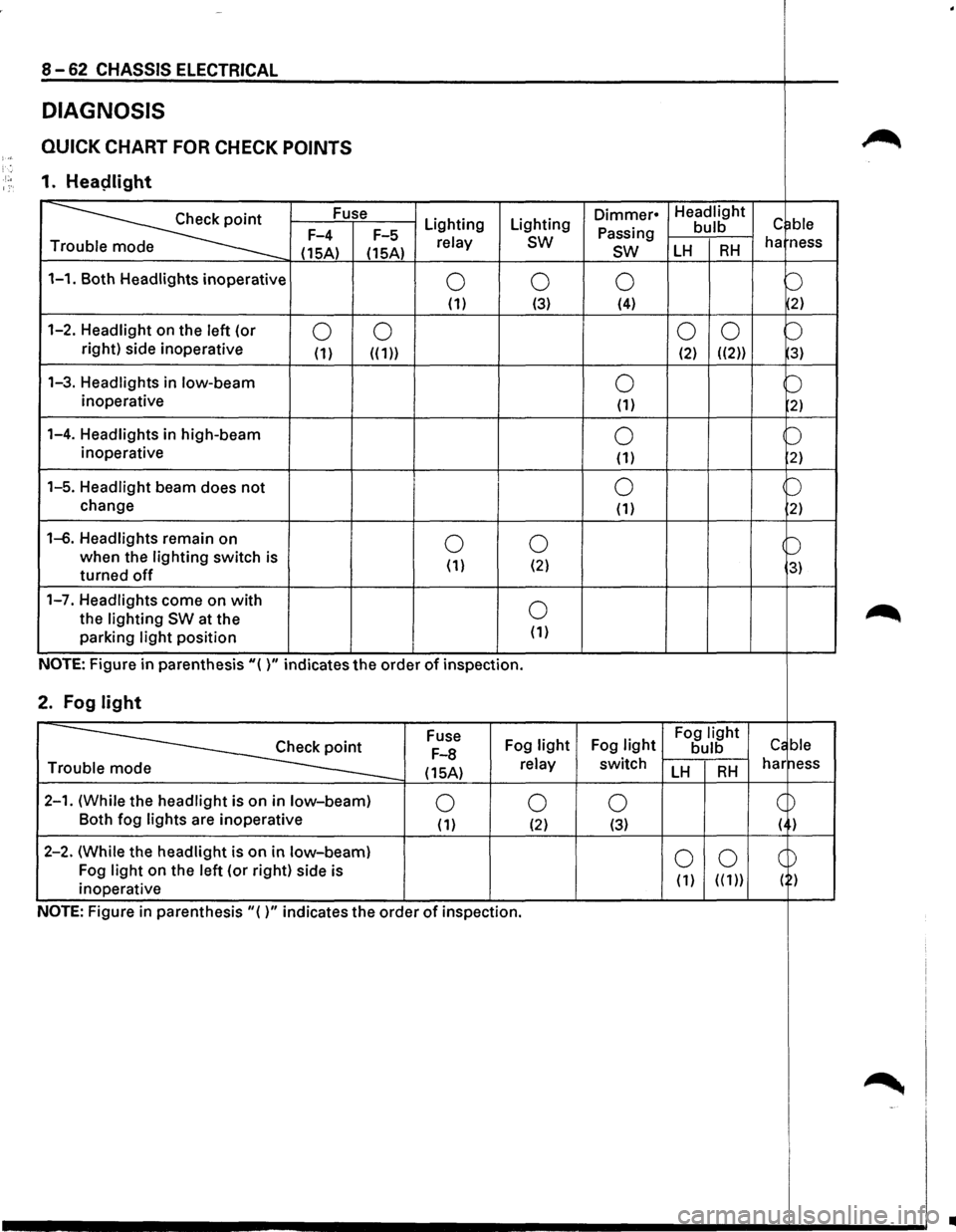
8-62 CHASSIS ELECTRICAL
DIAGNOSIS
QUICK CHART FOR CHECK POINTS ~ )-; '. ·'·• 1. Heaplight 1:·
~
Fuse Lighting Lighting Dimmer• Headlight c ~ble Passing bulb F-4
F-5 relay sw ha ness
T
(15A) (15A) sw LH RH
1-1. Both Headlights inoperative 0 0 0 b (1) (3) (4) 2)
1-2. Headlight on
the left (or 0 0 0
0 b right) side inoperative (1) ((1)) (2) ((2)) 3)
1-3. Headlights in low-beam 0 b inoperative (1) 2)
1-4. Headlights in high-beam 0 b inoperative
(1) 2)
1-5. Headlight beam does not 0 p
change (1) 2)
1-6. Headlights remain on 0 0 b when the lighting switch is
( 1) (2) 3) turned off
1-7. Headlights come on with 0 ~ the lighting SW at the
parking light position (1)
NOTE: Figure in parenthesis"( )" indicates the order of inspection.
2. Fog light
~
Fuse
Fog light Fog light Fog light Cc ble F-8 bulb
(15A) relay switch LH RH har ness Tr
2-1. (While the headlight is on in low-beam) 0 0 0 c ~ Both
fog lights are inoperative (1) (2) (3) ( )
2-2. (While the headlight is
on in low-beam) 0 0 CD Fog light on the left (or right) side is
( 1) ( ( 1)) ( ) inoperative
NOTE: Figure
in parenthesis"()" indicates the order of inspection.
~ -'
..
Page 1253 of 1928
![ISUZU TROOPER 1995 Workshop Manual CHASSIS ELECTRICAL 8-63
1-1. BOTH HEADLIGHTS INOPERATIVE
• IS THE LIGHTING RELAY NORMAL? I
I
I I
YES I NO I
I
I
• IS [[I[] GROUNDED SECURELY? I REPLACE THE LIGHTING RELAY I
I
I
I
YES](/img/61/57183/w960_57183-1252.png "ISUZU TROOPER 1995 Workshop Manual CHASSIS ELECTRICAL 8-63
1-1. BOTH HEADLIGHTS INOPERATIVE
• IS THE LIGHTING RELAY NORMAL? I
I
I I
YES I NO I
I
I
• IS [[I[] GROUNDED SECURELY? I REPLACE THE LIGHTING RELAY I
I
I
I
YES")
CHASSIS ELECTRICAL 8-63
1-1. BOTH HEADLIGHTS INOPERATIVE
• IS THE LIGHTING RELAY NORMAL? I
I
I I
YES I NO I
I
I
• IS [[I[] GROUNDED SECURELY? I REPLACE THE LIGHTING RELAY I
I
I
I
YES I NO I
I I
• IS THE DIODE NORMAL? J GROUND IT SECURELY I
I
I I
YES I NO I
I
I
• DISCONNECT THE LIGHTING SW CONNECTOR REPLACE THE DIODE J • IS THE BATTERY VOLTAGE APPLIED BETWEEN THE HARNESS
SIDE CONNECTOR 1 [[I[j AND GROUND?
I
I I
YES I NO I
I I
• REMOVE THE LIGHTING SW REPAIR A POOR CONNECTION AT THE CONNECTORS
• IS THERE CONTINUITY BETWEEN 1 [[I[] AND 7 ~WHEN OR AN OPEN CIRCUIT BETWEEN THE FUSUBLE LINK SETTING THE LIGHTING SWAT THE HEADLIGHT POSITION? FL-1 (80A) AND 1 ~
I
I I
I YES I NO I
1 I
REPAIR A POOR CONNECTION AT THE CONNECTORS OR AN REPAIR OR REPLACE THE LIGHTING SW I OPEN CIRCUIT BETWEEN THE HARNESS SIDE CONNECTOR 1WI] AND~ (GROUND) OF THE LIGHTING SW
Page 1254 of 1928
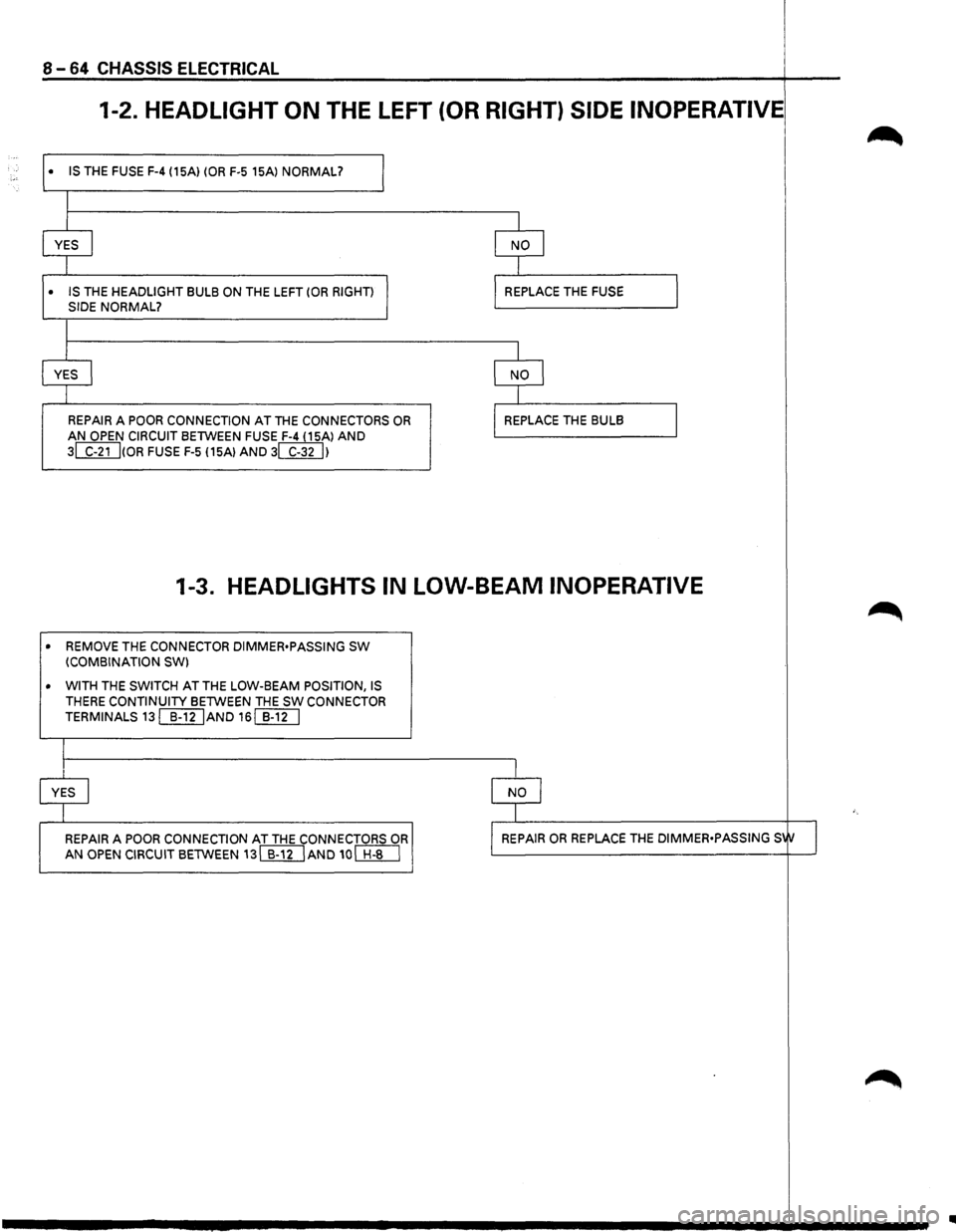
8 -64 CHASSIS ELECTRICAL
1-2. HEADLIGHT ON THE LEFT (OR RIGHT) SIDE INOPERATIVE
• IS THE FUSE F-4 (15A) (OR F-5 15Al NORMAL?
I
I
YES I
I
• IS THE HEADLIGHT BULB ON THE LEFT (OR RIGHT)
SIDE NORMAL?
I
I
YES I
I
I
REPAIR A POOR CONNECTION AT THE CONNECTORS OR
AN OPEN CIRCUIT BETWEEN FUSE F-4 (15Al AND
3~(0R FUSE F-5 115Al AND 3WUI
I
I NO I
I
I REPLACE THE FUSE
I
I NO I
I
I REPLACE THE BULB
I
I
1-3. HEADLIGHTS IN LOW-BEAM INOPERATIVE
• REMOVE THE CONNECTOR DIMMER•PASSING SW (COMBINATION SW)
• WITH
THE SWITCH AT THE LOW-BEAM POSITION, IS THERE CONTINUITY BETWEEN THE SW CONNECTOR
TERMINALS
13[[I[jAND 16[[1[]
I
I
YES I
I
REPAIR A POOR CONNECTION AT THE CONNECTORS OR
AN OPEN CIRCUIT BETWEEN 13[[ll]AND 10~
I
I NO I
I
I REPAIR OR REPLACE THE DIMMER•PASSING S1tJ I
Page 1255 of 1928
CHASSIS ELECTRICAL 8 .... 65
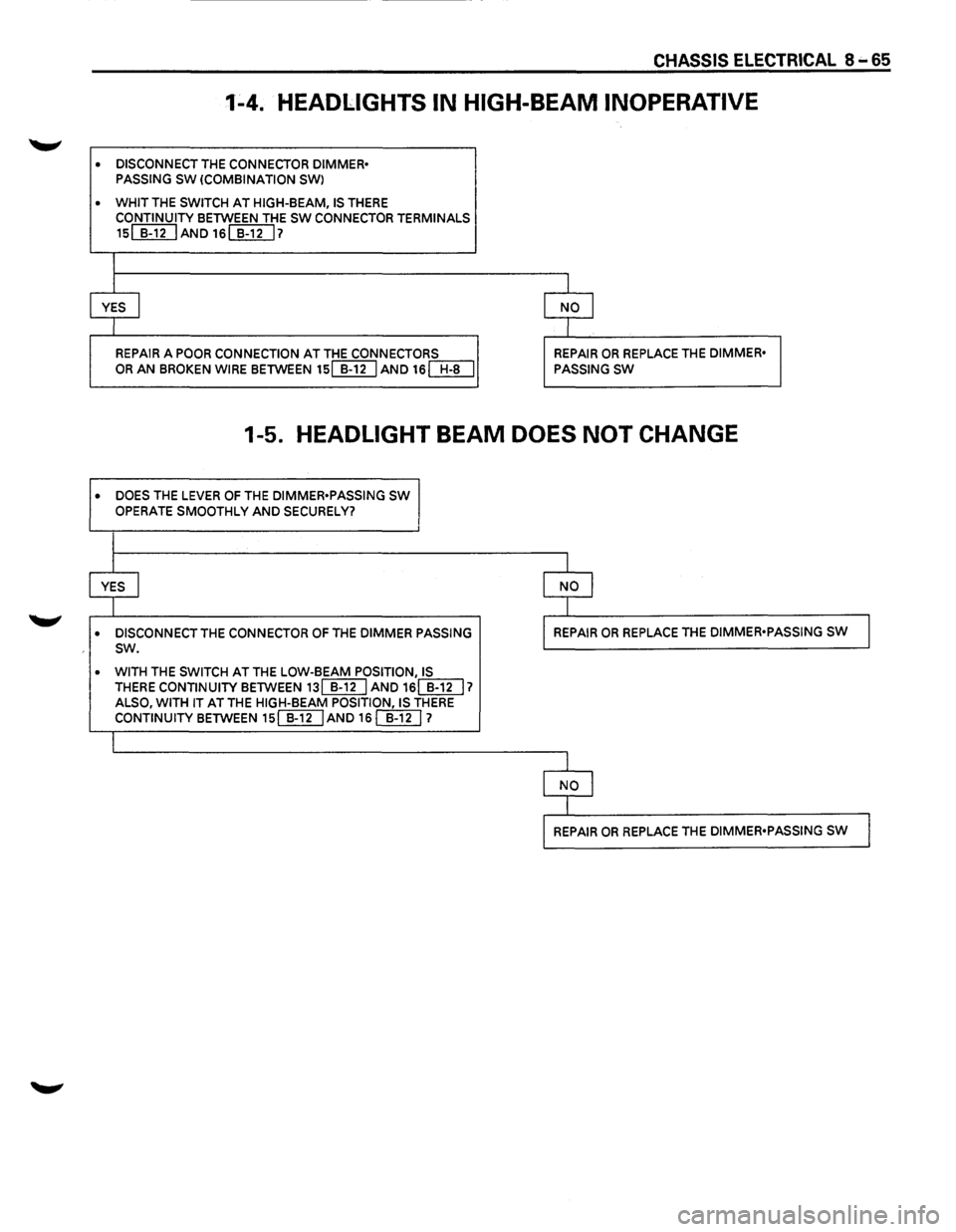
1-4. HEADLIGHTS IN HIGH-BEAM INOPERATIVE
• DISCONNECT THE CONNECTOR DIMMER•
PASSING SW (COMBINATION SWl
• WHIT THE SWITCH AT HIGH-BEAM, IS THERE
CONTINUITY BETWEEN THE SW CONNECTOR TERMINALS
15~AND16~7
I
I I
YES I NO I
I I
REPAIR A POOR CONNECTION AT THE CONNECTORS REPAIR OR REPLACE THE DIMMER•
OR AN BROKEN WIRE BETWEEN 15[[]IJAND 16[Jf[J PASSING SW
1-5. HEADLIGHT BEAM DOES NOT CHANGE
• DOES THE LEVER OF THE DIMMER•PASSING SW
OPERATE SMOOTHLY AND SECURELY?
I
I I
YES I
I NO I
I I
• DISCONNECT THE CONNECTOR OF THE DIMMER PASSING I REPAIR OR REPLACE THE DIMMER•PASSING sw J sw.
• WITH THE SWITCH AT THE LOW-BEAM POSITION, IS THERE CONTINUITY BETWEEN 13[[g] AND 16(]]U 1 ALSO, WITH IT AT THE HIGH-BEAM POSITION, IS THERE CONTINUITY BETWEEN 15(]]UAND 16 []}[) 1
I
l
I NO I
I
l REPAIR OR REPLACE THE DIMMER•PASSING SW J
Page 1256 of 1928
8 -66 CHASSIS ELECTRICAL
•
•
•
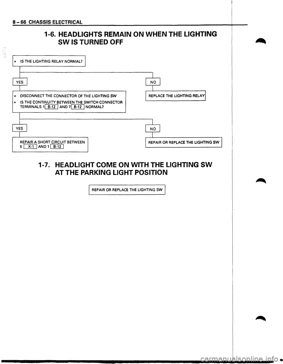
1-6. HEADLIGHTS REMAIN ON WHEN THE LIGHTING
SW IS TURNED OFF
IS THE LIGHTING RELAY NORMAL? I
I
I I
YES I I NO J
I I
DISCONNECT THE CONNECTOR OF THE LIGHTING SW I REPLACE THE LIGHTING RELAYI
IS
THE CONTINUITY BETWEEN THE SWITCH CONNECTOR
TERMINALS 1ITI[J AND 7[[ITJ NORMAL?
I
I I
YES I
I NO I
I I I I
REPAIR A SHORT CIRCUIT BETWEEN
5
ITI]AND1~ I REPAIR OR REPLACE THE LIGHTING sw I
1-7. HEADLIGHT COME ON WITH THE LIGHTING SW
AT THE PARKING LIGHT POSITION
I REPAIR OR REPLACE THE LIGHTING sw I
..
Page 1318 of 1928
8-128 CHASSIS ELECTRICAL
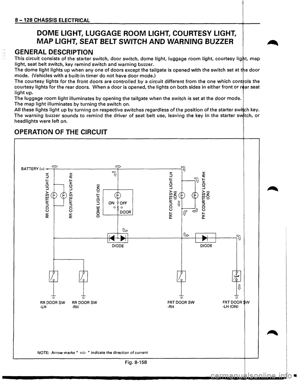
DOME LIGHT, LUGGAGE ROOM LIGHT, COURTESY LIGHT,
MAP LIGHT, SEAT BELT SWITCH AND WARNING BUZZER
GENERAL DESCRIPTION
This circuit consists of the starter switch, door switch, dome light, luggage room light, courtesy lig t, map
light, seat belt switch, key remind switch and warning buzzer.
The dome
light lights up when any one of doors except the tailgate is opened with the switch set at t e door
mode. (Vehicles with a built-in timer do not have door mode.) !
The courtesy lights for the front doors are controlled by a circuit different from the one which cont ols the
courtesy
lights for the rear doors. When a door is opened, the lights on both sides in either front or r ar seat
light up.
The
luggage room light illuminates by opening the tailgate when the switch is set at the door mode.
The
map light illuminates by turning the switch on.
All these lights light up by turning on respective switches regardless of the position of the starter swi ch key.
The
warning buzzer sounds to remind the driver of seat belt use, leaving the key in the starter sv.. tch, or
headlights were left on.
OPERATION OF THE CIRCUIT
BATIERY (+) _....,.=>..:.__ _________ =>~---------lij
l} :X: :X: ...J a: ~ ~ :X: :X: Q .....__ (.!) ...J :J
~~ ®~ II: li: :::> r----:::> 0 0 u u a: a:
a: a:
z Q r---t----,
~ Go (.!) :J w ON OFF 0 0
~ DOOR 0 '-----+------'
~----------~~~~~~~~lr-l ____________ ,_b __ +-~~~-'--~'---,~ II...... 111"""11 Ill"""' J
-:..._ -=-
RRDOORSW RRDOORSW -LH -RH
DIODE DIODE
-=
FRTDOOR SW -RH
NOTE: Arrow marks u =:> H indicate the direction of current
Fig. 8-158
FRTDOOR W -LH (ON)
•
Page 1326 of 1928
8 -136 CHASSIS ELECTRICAL
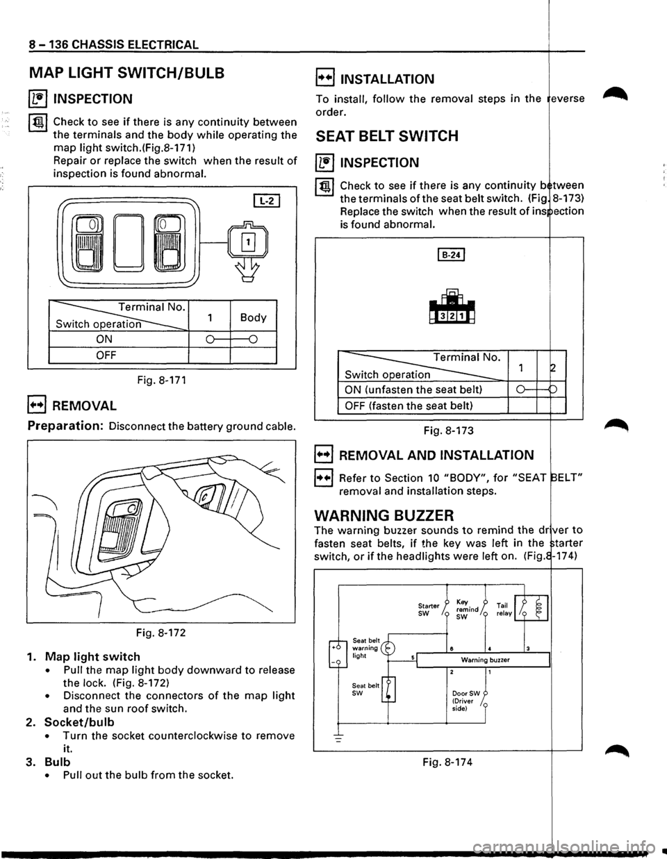
MAP LIGHT SWITCH/BULB
~ INSPECTION
~~~ Check to see if there is any continuity between
the terminals and the body while operating the
map light switch.(Fig.8-171)
Repair
or replace the switch when the result of
inspection is found abnormal.
I" ~ [IT]
ron
0~/~ ~
'
~· 1 Body
n
ON 0 {)
OFF
Fig. 8-171
B REMOVAL
E) INSTALLATION
To install, follow the removal steps in the everse
order.
SEAT BELT SWITCH
~ INSPECTION
I~ l Check to see if there is any continuity b tween
the terminals of the seat belt switch. (Fig 8-173)
Replace the switch when the
result of ins ection
is found abnormal.
Switch operation
ON (unfasten the seat belt)
OFF (fasten the seat belt)
Preparation: Disconnect the battery ground cable. Fig. 8-173
Fig. 8-172
1.
Map light switch
• Pull the map light body downward to release
the
lock. (Fig. 8-172)
• Disconnect the connectors of the map light
and the sun roof switch.
2. Socket/bulb
• Turn the socket counterclockwise to remove
it.
3.
Bulb
• Pull out the bulb from the socket.
B REMOVAL AND INSTALLATION
1++1 Refer to Section 10 "BODY", for "SEAT ELT"
removal and installation steps.
WARNING BUZZER
The warning buzzer sounds to remind the dr ver to
fasten seat belts, if the key was left in the tarter
switch,
or if the headlights were left on. (Fig. -174)
Seat belt warning light
Seat belt
sw
Starter sw
8
Warning buzzer
DoorSW (Driver
side)
Fig. 8-174
..
Page 1460 of 1928
8-270 CHASSIS ELECTRICAL
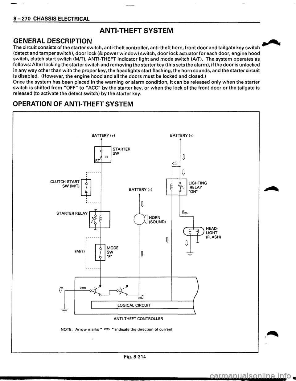
ANTI-THEFT SYSTEM
GENERAL DESCRIPTION .......
The circuit consists ofthe starter switch, anti-theft controller, anti-theft horn, front door and tailgate key switch
(detect and tamper switch),
door lock (&power window) switch, door lock actuator for each door, engine hood
switch, clutch start switch (MfT),
ANTI-THEFT indicator light and mode switch (AfT). The system operates as
follows: After locking the starter switch and removing the starter key (this sets the alarm),
ifthe door is unlocked
in any
way other than with the proper key, the headlights start flashing, the horn sounds, and the starter circuit
is disabled. (However,
the engine hood and all the doors must be locked and closed.)
Once the system has been placed in the warning or alarm condition, it can be released only when the starter
switch is shifted
from "OFF" to "ACC" by the starter key, or when the lock of the front door or the tailgate is
released (to activate the detect switch)
by the starter key.
OPERATION OF ANTI-THEFT SYSTEM
'
'
CLUTCH START m
SW(M/Tiw
' '
'
BATIERY(+)
0 ST
STARTER sw
BATIERY(+)
L------
STARTER RELAY
' ' (MIT):
'
'
'
HORN
(SOUND)
ANTI-THEFT CONTROLLER
BATIERY(+)
LIGHTING
RELAY
"ON"
HEADLIGHT (FLASH)
NOTE: Arrow marks u ~ u indicate the direction of current
Fig. 8-314
•
Page 1465 of 1928
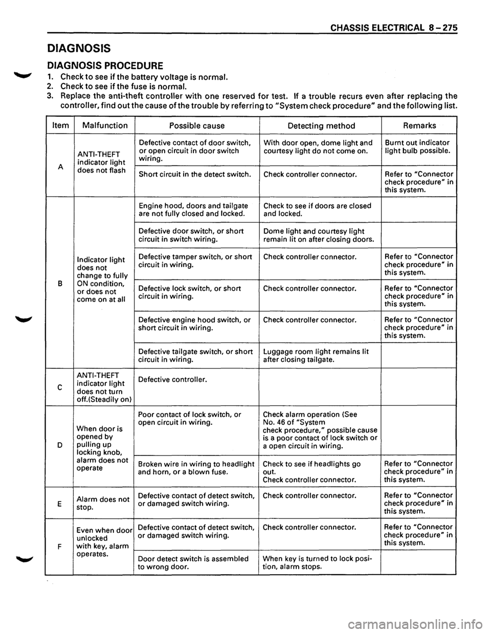
DIAGNOSIS
DIAGNOSIS PROCEDURE
.......,. 1. Check to see ifthe battery voltage is normal.
2. Check to see if the fuse is normal.
CHASSIS ELECTRICAL 8 -275
3. Replace the anti-theft controller with one reserved for test. If a trouble recurs even after replacing the
controller, find
out the cause of the trouble by referring to "System check procedure" and the following list.
Item Malfunction
Possible
cause Detecting method Remarks
Defective
contact of door switch,
With door open, dome light and Burnt
out indicator
ANTI-THEFT or open circuit in door switch courtesy light do not come on. light bulb possible.
indicator light wiring.
A does
not flash Short circuit in the detect switch.
Check controller connector. Refer to "Connector check procedure" in
this system.
Engine hood, doors and
tailgate Check to see if doors are closed are not fully closed and locked. and locked.
Defective door switch, or short Dome light and courtesy light circuit in switch wiring.
remain lit on after closing doors.
Indicator light Defective tamper switch, or short Check controller connector. Refer
to "Connector
does not circuit in wiring. check procedure" in
change to
fully this system.
B
ON condition, Defective lock switch, or short Check controller connector. Refer
to "Connector or does not come on at all circuit in wiring. check procedure" in
this system.
Defective engine hood switch, or Check
controller connector. Refer
to "Connector
short circuit in wiring. check
procedure" in
this system.
Defective
tailgate switch, or short Luggage room light remains lit circuit in wiring. after closing tailgate.
ANTI-THEFT
Defective controller.
c indicator light
does not turn off.(Steadily on) Poor contact
of lock switch, or Check alarm operation (See
When
door is open
circuit in wiring. No. 46 of "System
check procedure," possible cause
opened by
is a poor contact of lock switch or D pulling up
a open circuit in wiring. locking knob, alarm does not Broken wire in wiring to headlight Check to see if headlights go Refer
to "Connector operate
and horn, or a blown fuse. out. check procedure" in
Check
controller connector. this
system.
Alarm does not Defective contact of detect switch, Check controller connector.
Refer to "Connector
E
stop. or damaged switch wiring. check procedure" in
this system.
Even when
door Defective contact of detect switch, Check controller connector. Refer
to "Connector
unlocked
or damaged switch wiring. check procedure" in
F
with key, alarm this system.
operates. Door detect switch is
assembled When key is turned to lock posi-
to
wrong door. tion, alarm stops.