ISUZU TROOPER 1995 Workshop Manual
Manufacturer: ISUZU, Model Year: 1995, Model line: TROOPER, Model: ISUZU TROOPER 1995Pages: 1928
Page 1651 of 1928
Suppleme~tralnt System
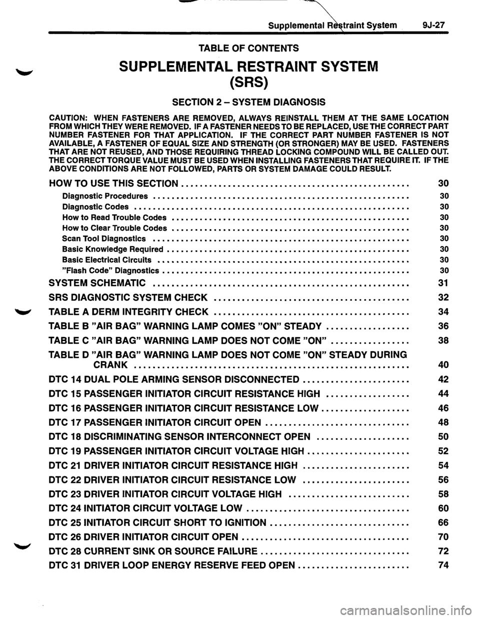
TABLE OF CONTENTS
SUPPLEMENTAL RESTRAINT SYSTEM
{SRS)
SECTION 2-SYSTEM DIAGNOSIS
9J-27
CAUTION: WHEN FASTENERS ARE REMOVED, ALWAYS REINSTALL THEM AT THE SAME LOCATION
FROM WHICH THEY WERE REMOVED. IF A FASTENER NEEDS TO BE REPLACED, USE THE CORRECT PART
NUMBER
FASTENER FOR THAT APPLICATION. IF THE CORRECT PART NUMBER FASTENER IS NOT
AVAILABLE, A FASTENER OF EQUAL SIZE AND STRENGTH (OR STRONGER) MAY BE USED. FASTENERS
THAT ARE NOT REUSED, AND THOSE REQUIRING THREAD LOCKING COMPOUND WILL BE CALLED OUT.
THE CORRECT TORQUE VALUE
MUST BE USED WHEN INSTALLING FASTENERS THAT REQUIRE IT. IF THE
ABOVE CONDITIONS ARE NOT FOLLOWED, PARTS OR SYSTEM DAMAGE COULD RESULT.
HOW TO USE THIS SECTION . . . . . . . . • . . . . . . . . . . . • . . . . . . . . . • • • • • • . • . • • . . . . . • • . 30
Diagnostic Procedures • • • • • • • • • • • • • • • • • • • • • • • • • • • • • • • • • • • • • • • • • • • • • • • • • • • • • • • 30
Diagnostic Codes • • • • • • • • • • • • • • • • • • • • • • • • • • • • • • • • • • • • • • • • • • • • • • • • • • • • • • • • • • • 30
How to Read Trouble Codes • • • • • • • • • • • • • • • • • • • • • • • • • • • • • • • • • • • • • • • • • • • • • • • • • • • 30
How to Clear Trouble Codes • • • • • • • • • • • • • • • • • • • • • • • • • • • • • • • • • • • • • • • • • • • • • • • • • • • 30
Scan
Tool Diagnostics • • • • • • • • • • • • • • • • • • • • • • • • • • • • • • • • • • • • • • • • • • • • • • • • • • • • • • • 30
Basic Knowledge Required • • • • • • • • • • • • • • • • • • • • • • • • • • • • • • • • • • • • • • • • • • • • • • • • • • • • 30
Basic Electrical Circuits • • • • • • • • • • • • • • • • • • • • • • • • • • • • • • • • • • • • • • • • • • • • • • • • • • • • • • 30
"Flash Code"
Diagnostics • • • • • • • • • • • • • • • • • • • • • • • • • • • • • • • • • • • • • • • • • • • • • • • • • • • • • 30
SYSTEM SCHEMATIC . . • . • . . . . • • • • • • • • . • . . • . . • . • • . • • • . . . • • . . . . . . . • • . . • • • • • • • 31
SRS DIAGNOSTIC SYSTEM CHECK • . • • • . • • . • . . . . . • . • . • . • • • . . . • . • . . • . . . . . . . • . 32
,_.., TABLE A DERM INTEGRITY CHECK • . • • • . . . . . . . . . . • . • • • . • • • . • • . • . . . • . . . . . . . . . 34
TABLE B "AIR BAG" WARNING LAMP COMES "ON" STEADY . . . . . . . . . . . . . . . . • . 36
TABLE C "AIR BAG" WARNING LAMP DOES NOT COME "ON" . . . . . . . . . . . . . . . • . 38
TABLED "AIR BAG" WARNING LAMP DOES NOT COME "ON" STEADY DURING
CRANK .......................................................... .
DTC 14 DUAL POLE ARMING SENSOR DISCONNECTED ..•.••••••.•...........
DTC 15 PASSENGER INITIATOR CIRCUIT RESISTANCE HIGH •.................
DTC 16 PASSENGER INITIATOR CIRCUIT RESISTANCE LOW ...........•...••..
DTC 17 PASSENGER INITIATOR CIRCUIT OPEN ..••.•.......•.•••...•......••.
DTC 18 DISCRIMINATING SENSOR INTERCONNECT OPEN ................... .
DTC
19 PASSENGER INITIATOR CIRCUIT VOLTAGE HIGH •....•.....••.•..•.•..
DTC 21 DRIVER INITIATOR CIRCUIT RESISTANCE HIGH
DTC 22 DRIVER INITIATOR CIRCUIT RESISTANCE LOW ..••••.••.•.••..•.•.•••
DTC 23 DRIVER INITIATOR CIRCUIT VOLTAGE HIGH ........................•.
DTC 24 INITIATOR CIRCUIT VOLTAGE LOW .....••....•..•...•................
DTC 25 INITIATOR CIRCUIT SHORT TO IGNITION .............•.............•..
DTC 26 DRIVER INITIATOR CIRCUIT OPEN •.••........................••..•.••
DTC 28 CURRENT SINK OR SOURCE FAILURE ............................... .
DTC 31 DRIVER LOOP ENERGY RESERVE FEED OPEN ....................... .
40
42
44
46
48
50
52
54
56
58
60
66
70
72
74
Page 1652 of 1928
-
9J-28 Supplemental Restraint System
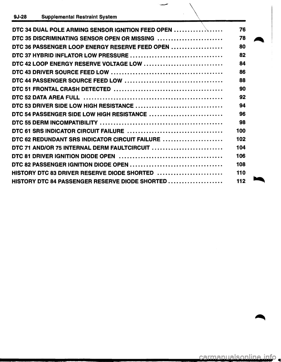
DTC 34 DUAL POLE ARMING SENSOR IGNITION FEED OPEN •••••••.••• \> ...... .
DTC 35 DISCRIMINATING SENSOR OPEN OR MISSING •••••••••••••••••.•\
•••••
DTC 36 PASSENGER LOOP ENERGY RESERVE FEED OPEN ••••••••••••••..•••
76
78
~
80
DTC 37 HYBRID INFLATOR LOW PRESSURE . . • • • • • • • • . • • • • • • • • • • . • • • . .
.
• • • • . . 82
DTC 42
LOOP ENERGY RESERVE VOLTAGE LOW • • • • • • • • • • • • • . • • • • . .
.
• . • . . • • • 84
DTC 43
DRIVER SOURCE FEED LOW • • . • • • • • • • • • • • • • • • • • • • • • • • • • . • • • • . • • • • • • • 86
DTC 44
PASSENGER SOURCE FEED LOW • . • • . • • • • • • • • • • • • • • • . . • . • . • . . • • . . . • • 88
DTC
51 FRONTAL CRASH DETECTED • • • • • . • • • • • • • • . • • • • • • • • • • • • • • • . . • • • . • • • • 90
DTC 52 DATA AREA FULL . . . . . . . . . . . . . . . . . . . . . . . . . . . . . . . . . . . . . . . . . . . . . . . . . . . 92
DTC 53 DRIVER SIDE LOW HIGH RESISTANCE • • • • • • • • • • • • • • • • • • • . • • • • • . • • • • . • 94
DTC 54
PASSENGER SIDE LOW HIGH RESISTANCE • • • • . • • • • • • . • • • • • . . • . • . . • . • 96
DTC 55 DERM
INCOMPATIBILITY • • • • . • • • . • . • • • • • • • • • • • • • • • • • • • • • . . • . . • . • • • • . • 98
DTC
61 SRS INDICATOR CIRCUIT FAILURE • • • • • • • • • • • • • • • • • • • • • • • • . • • • . • • • • • • 100
DTC 62 REDUNDANT SRS INDICATOR CIRCUIT FAILURE • • • • • • • . .
. .
• . .
. . . .
• • . • 102
DTC 71 AND/OR 75 INTERNAL DERM FAULTCIRCUIT • • • • • • • • • • • • • • • . • • • • • • • . . • 104
DTC 81 DRIVER IGNITION DIODE OPEN • . • • • • • • • • • • • • • • • • • • • • • • • • • • • • • • • • • • • • 106
DTC 82 PASSENGER IGNITION DIODE OPEN • • • • • • • • • • • • • • • • • • • • • • • • • . • • • • • • . • 108
HISTORY
DTC 83 DRIVER RESERVE DIODE SHORTED • • • • • • • • • • • • • . • • . • • • . • • • 110
HISTORY
DTC 84 PASSENGER RESERVE DIODE SHORTED •••••••••.•••.•..•••
Page 1653 of 1928
MEMO
\ Supplemental Restraint Systern 9J-29 ( \,
Page 1654 of 1928
9J-30 Supplemental Restraint System (SRS)
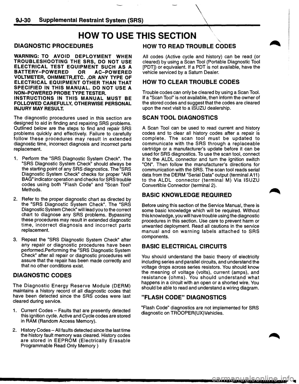
HOW TO USE THIS SECTION
DIAGNOSTIC PROCEDURES
WARNING: TO AVOID DEPLOYMENT WHEN
TROUBLESHOOTING THE SRS, DO NOT USE
ELECTRICAL TEST EQUIPMENT SUCH AS A
BATTERY-POWERED OR AC-POWERED
VOLTMETER, OHMMETR,ETC. ,OR ANY TYPE OF
ELECTRICAL EQUIPMENT OTHER THAN THAT
SPECIFIED IN THIS MANUAL. DO NOT USE A
NON-POWERED PROBE TYPE TESTER.
INSTRUCTIONS IN THIS MANUAL MUST BE
FOLLOWED CAREFULLY, OTHERWISE PERSONAL
INJURY
MAY RESULT.
The diagnostic procedures used in this section are
designed to aid
in finding and repairing SRS problems.
Outlined below
are the steps to find and repair SRS
problems quickly
and effectively. Failure to carefully
follow these procedures may result in extended
diagnostic time, incorrect diagnosis and incorrect parts
replacement.
1. Perform the "SRS Diagnostic System Check". The
"SRS Diagnostic System Check" should always be
the starting point of any SRS diagnostics. The "SRS
Diagnostic System Check" checks for proper "AIR
BAG" indicator operation and checks for SRS trouble
codes using both "Flash Code" and "Scan Tool"
Methods.
2. Refer to the proper diagnostic chart as directed by
the
"SRS Diagnostic System Check". The "SRS
Diagnostic System Check" will lead you to the correct
chart to diagnose any
SRS problems. Bypassing
these procedures may
result in extended diagnostic
time, incorrect diagnosis and incorrect parts
replacement.
3. Repeat the "SRS Diagnostic System Check" after
any repair
or diagnostic procedures have been
performed.Performing the
"SRS Diagnostic System
Check" after all repair or diagnostic procedures will
assure that the repair has been made correctly and
that no other conditions exist.
DIAGNOSTIC CODES
The Diagnostic Energy Reserve Module (DERM)
maintains a history record of all diagnostic codes that
have been detected since the
SRS codes were last
cleared
during service.
1. Current Codes -Faults that are presently detected
this ignition
cycle. Active and Cycle codes are stored
in RAM (Random Access Memory).
2. History
Codes-All faults detected since the last time
the history
fault memory was cleared. History codes
are stored in EEPROM (Electrically Erasable
Programmable Read Only Memory )
HOW TO READ TROUBLE CODES
All codes (Active cycle and history) can be read (or
cleared) by using a Scan Tool (Portable Diagnostic Tool
[PDT)) or equivalent. If a PDT is not available, have the
vehicle serviced by a Saturn Dealer.
HOW TO CLEAR TROUBLE CODES
Trouble codes can only be cleared by using a Scan Tool.
If
a "Scan Tool" is not available, then inform the owner of
the stored codes and suggest that the codes are
cleared
upon the next visit to a ISUZU dealership.
SCAN TOOL DIAGNOSTICS
A Scan Tool can be used to read current and history
codes and to
clear all history codes after a repair is
complete. The scan tool must be updated to
communicate with the
SRS through a replaceable
cartridge or a manufacturer's update before it can be
used for
SRS diagnostics. To use the scan tool, connect
it to the ALDL connector and turn the ignition switch
"ON". Then follow the manufacturer's directions for
communication with the
SRS. The scan tool reads serial
data from the DERM "Serial Data" output (terminal A 11)
to the ALDL connector (terminal M) Via ISUZU
Convertible Connector (terminal 2).
BASIC KNOWLEDGE REQUIRED
Before using this section of the Service Manual, there is
some basic
knowledge which will be required. Without
this knowledge, you
will have trouble using the diagnostic
procedures
in this section. Use care to prevent harm or
unwanted
deployment. Read all cautions in the service
manual and on warning labels attached to SRS
components.
BASIC ELECTRICAL CIRCUITS
You should understand the basic theory of electricity
including series and parallel circuits, and understand the
voltage drops across series resistors. You should know
the meaning of
voltage (volts), current (amps), and
resistance (ohms). You should understand what
happens in a circuit with an open or a shorted wire. You
should be able to read and understand a wiring diagram.
"FLASH CODE" DIAGNOSTICS
"Flash Code" diagnostics are not implemented for SRS
diagnostic on TROOPER(UX)Vehicles.
Page 1655 of 1928
Supplemental Restraint System
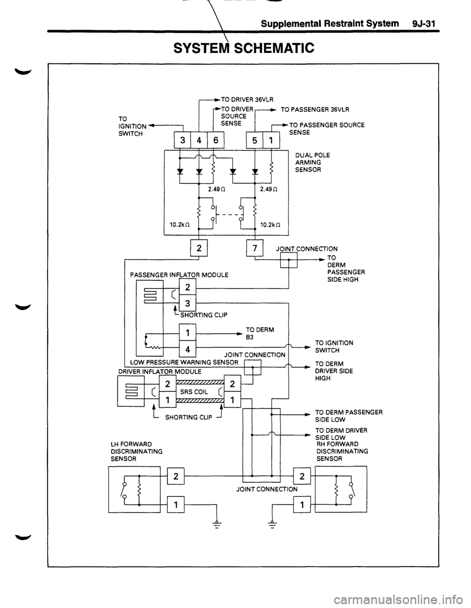
SYSTEM SCHEMATIC
TO IGNITION-----,
TO DRIVER 36VLR
SWITCH ,.--Ji........,--L--r-1----,
TO PASSENGER 36VLR
TO PASSENGER SOURCE
SENSE
DUAL POLE ARMING SENSOR
JOINT CONNECTION
'-----+---.--+---TO
PASSENGER INFLATOR
MODULE
1-----.-TO DERM 83
JOINT CONNECTION LOW PRESSURE WARNING SENSOR
LH FORWARD DISCRIMINATING
SENSOR
DERM PASSENGER
SIDE HIGH
TO IGNITION
SWITCH
TO
DERM DRIVER SIDE
HIGH
TO
DERM PASSENGER
SIDE LOW
TO
DERM DRIVER
SIDE LOW RH FORWARD DISCRIMINATING
SENSOR
9J-31
Page 1656 of 1928
9J-32 Supplemental Restraint System (SRS)
SRS DIAGNOSTIC SYSTEM CHECK
WARNING: TO AVOID DEPLOYMENT WHEN
TROUBLESHOOTING THE SRS, DO NOT USE
ELECTRICAL TEST EQUIPMENT SUCH AS A
BATTERY-POWERED OR AC-POWERED
VOLTMETER, OHMMETER, ETC., OR ANY TYPE OF
ELECTRICAL EQUIPMENT OTHER THAN THAT
SPECIFIED IN THIS MANUAL. DO NOT USE A
NON-POWERED PROBE TYPE TESTER.
INSTRUCTIONS IN THIS MANUAL MUST BE
FOLLOWED CAREFULLY, OTHERWISE PERSONAL
INJURY
MAY RESULT.
The diagnostic procedures used in this section are
designed to find and repair
SRS malfunctions. To get the
best results, it is important to use the diagnostic charts
and
follow the sequence listed below:
A. PERFORM THE "SRS DIAGNOSTIC SYSTEM
CHECK."
The "SRS Diagnostic System Check" must be the
starting point of any
SRS diagnostics. The "SRS
Diagnostic System Check" checks for proper "AIR
BAG"
warning lamp operation, the ability of the
DERM to communicate through the
"Serial Data" line
and whether SRS diagnostic trouble codes exist.
B. REFER TO THE PROPER DIAGNOSTIC CHART
AS
DIRECTED BY THE SRS DIAGNOSTIC
SYSTEM CHECK."
The "SRS Diagnostic System Check" will lead you to
the correct chart to diagnose any
SRS malfunctions.
Bypassing these procedures may result
in extended
diagnostic time, incorrect diagnosis and incorrect
parts replacement.
C. REPEAT THE "SRS DIAGNOSTIC SYSTEM
CHECK" AFTER ANY REPAIR OR DIAGNOSTIC
PROCEDURES HAVE
BEEN PERFORMED.
Performing
the "SRS Diagnostic System Check"
after all repair or diagnostic procedures will ensure
that the repair has been made correctly and that no
other malfunctions exist.
CIRCUIT DESCRIPTION
When the ignition switch is first turned "ON,""Ignition 1"
voltage is applied from the "C-22·C-23" fuse to the
DERM at the
"Ignition 1" input terminals "A9" and "A10"
and from the "C-21" fuse to the DERM at the "Redundant
Indicator Ignition 1" input terminal "B2". The DERM
responds by flashing the
"AIR BAG" warning lamp seven
times while performing tests on the
SRS.When the
engine is being cranked,
"Starter'' voltage is applied from
the
"C-1" fuse to the DERM at the "Crank" input terminal
"B10".The DERM responds by grounding the "SRS
Indicator"
output terminal "B 1" until "Starter" voltage is
removed from the "Crank" input. This results in the "AIR
BAG" warning lamp being "ON" steady during
cranking.After cranking, the DERM will flash the "AIR
BAG"
warning lamp six times and perform tests on the
SRS.
NOTES ON SYSTEM CHECK CHART ~
1. The "AIR BAG" warning lamp should flash seven
times after ignition is first turned
"ON."
2. The "AIR BAG" warning lamp should remain "ON"
steady during cranking.
3. When the "AIR BAG" warning lamp flashes four
times during
"Bulb Check" this indicates a
malfunction
in the redundant lamp driver circuitry.
These malfunctions are diagnosed by
DTC 62 chart.
4. After cranking, the "AIR BAG" warning lamp should
flash six times then go
"OFF."
5. Improper operation of the "AIR BAG" warning lamp
is indicated. This test differentiates a warning lamp
stays
"ON" condition from a warning lamp does not
come
"ON" condition.
6. This test checks for the proper operation of the
"Serial Data" line. This test will also determine
whether history diagnostic trouble codes are stored
and, if so, identify them.
7. This test checks for proper operation of the
"Serial
Data"
line. This test will also identify the stored
diagnostic trouble codes and
whether they are
current or history.
~
DIAGNOSTIC AIDS
The order in which diagnostic trouble codes are
diagnosed is very important. Failure to diagnose the
diagnostic trouble codes in the order specified may result
in extended diagnostic time, incorrect diagnosis and
incorrect parts replacement.
Page 1657 of 1928
Supplemental Restraint System 9J-33
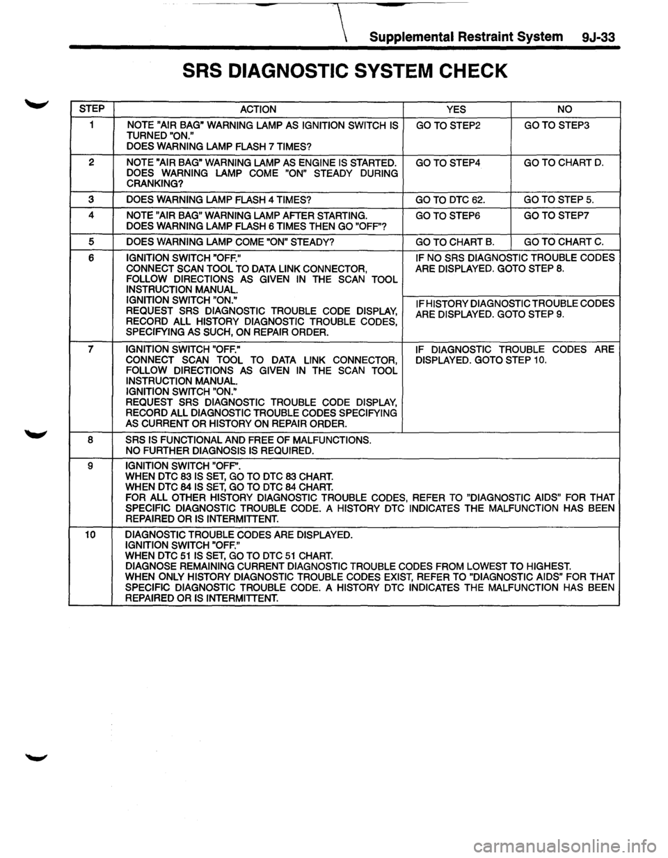
SRS DIAGNOSTIC SYSTEM CHECK
STEP
ACTION YES NO
1 NOTE "AIR BAG" WARNING LAMP AS IGNITION SWITCH IS GOTOSTEP2 GOTOSTEP3 TURNED "ON."
DOES WARNING
LAMP FLASH 7 TIMES?
2 NOTE "AIR BAG" WARNING LAMP AS ENGINE IS STARTED. GOTOSTEP4 GO TO CHART D. DOES WARNING LAMP COME "ON" STEADY DURING
CRANKING?
3 DOES WARNING LAMP FLASH 4 TIMES? GOTO DTC62. GO TO STEPS.
4 NOTE "AIR BAG" WARNING LAMP AFTER STARTING. GOTOSTEP6 GOTOSTEP7 DOES WARNING LAMP FLASH 6 TIMES THEN GO "OFF"?
5 DOES WARNING LAMP COME "ON" STEADY? GO TO CHART B. GO TO CHART C.
6 IGNITION SWITCH "OFF." IF
NO SRS DIAGNOSTIC TROUBLE CODES
CONNECT SCAN TOOL TO
DATA LINK CONNECTOR, ARE DISPLAYED. GOTO STEP 8. FOLLOW DIRECTIONS AS GIVEN IN THE SCAN TOOL
INSTRUCTION MANUAL.
IGNITION SWITCH "ON."
IF HISTORY DIAGNOSTIC TROUBLE CODES
REQUEST SRS DIAGNOSTIC TROUBLE CODE DISPLAY, ARE DISPLAYED. GOTO STEP 9. RECORD ALL HISTORY DIAGNOSTIC TROUBLE CODES,
SPECIFYING AS SUCH, ON REPAIR ORDER.
7 IGNITION SWITCH "OFF." IF DIAGNOSTIC TROUBLE CODES ARE
CONNECT SCAN TOOL TO DATA LINK CONNECTOR, DISPLAYED. GOTO STEP 10. FOLLOW DIRECTIONS AS GIVEN IN THE SCAN TOOL
INSTRUCTION MANUAL. IGNITION SWITCH "ON."
REQUEST SRS DIAGNOSTIC
TROUBLE CODE DISPLAY, RECORD ALL DIAGNOSTIC TROUBLE CODES SPECIFYING
AS CURRENT OR HISTORY ON REPAIR ORDER.
8
SRS IS FUNCTIONAL AND FREE OF MALFUNCTIONS.
NO FURTHER DIAGNOSIS IS REQUIRED.
9 IGNITION SWITCH "OFP'. WHEN DTC 83 IS SET, GO TO DTC 83 CHART. WHEN DTC 84 IS SET, GO TO DTC 84 CHART. FOR ALL OTHER HISTORY DIAGNOSTIC TROUBLE CODES, REFER TO "DIAGNOSTIC AIDS" FOR THAT
SPECIFIC DIAGNOSTIC TROUBLE CODE. A HISTORY DTC INDICATES THE MALFUNCTION HAS BEEN REPAIRED OR IS INTERMITTENT.
10 DIAGNOSTIC
TROUBLE CODES ARE DISPLAYED.
IGNITION SWITCH "OFF."
WHEN DTC 51 IS SET, GO TO DTC 51 CHART. DIAGNOSE REMAINING CURRENT DIAGNOSTIC TROUBLE CODES FROM LOWEST TO HIGHEST. WHEN ONLY HISTORY DIAGNOSTIC TROUBLE CODES EXIST, REFER TO "DIAGNOSTIC AIDS" FOR THAT SPECIFIC DIAGNOSTIC TROUBLE CODE. A HISTORY DTC INDICATES THE MALFUNCTION
HAS BEEN
REPAIRED OR IS INTERMITTENT.
Page 1658 of 1928
9J-34 Supplemental Restraint System
TABLE A
DERM INTEGRITY CHECK
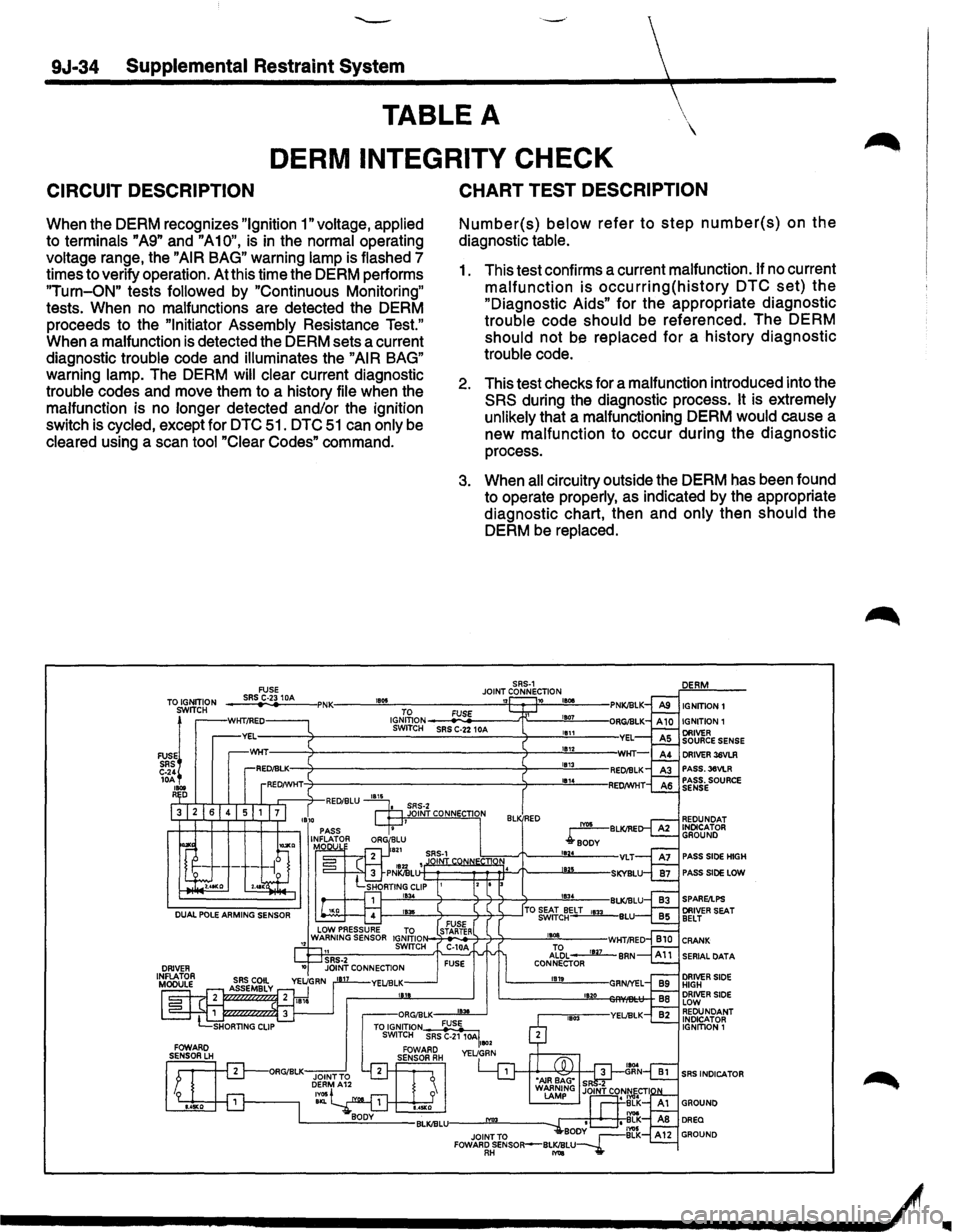
CIRCUIT DESCRIPTION
When the DERM recognizes "Ignition 1" voltage, applied
to terminals "A9" and "A10", is in the normal operating
voltage range, the "AIR BAG" warning lamp is flashed 7
timestoverifyoperation. At this time the DERM performs
"Turn-ON" tests followed by "Continuous Monitoring"
tests. When no malfunctions are detected the DERM
proceeds to the
"Initiator Assembly Resistance Test."
When a malfunction
is detected the DERM sets a current
diagnostic
trouble code and illuminates the "AIR BAG"
warning lamp. The DERM will clear current diagnostic
trouble codes and move them to a history file when the
malfunction is no
longer detected and/or the ignition
switch is
cycled, except for DTC 51. DTC 51 can only be
cleared using a scan tool "Clear Codes" command.
TO IGNITION SWITCH
FUSEl SRS C-24 lOA .... R D
CHART TEST DESCRIPTION
Number(s) below refer to step number(s) on the
diagnostic table.
1. This test confirms a current malfunction. If no current
malfunction is occurring(history DTC set) the
"Diagnostic Aids" for the appropriate diagnostic
trouble code should be referenced. The DERM
should not be replaced for a history diagnostic
trouble code.
2. This test checks for a malfunction introduced into the
SRS during the diagnostic process. It is extremely
unlikely
that a malfunctioning DERM would cause a
new malfunction to occur during the diagnostic
process.
3. When all circuitry outside the DERM has been found
to operate
properly, as indicated by the appropriate
diagnostic chart, then and
only then should the
DERM be
replaced.
IGNITION!
IGNITION
1
DRIVER 36VLR PASS.36VLR PASS. SOURCE SENSE
PASS SlOE HIGH
PASS SIDE LOW
SPARE/LPS
--------------------~&--~/
..
Page 1659 of 1928
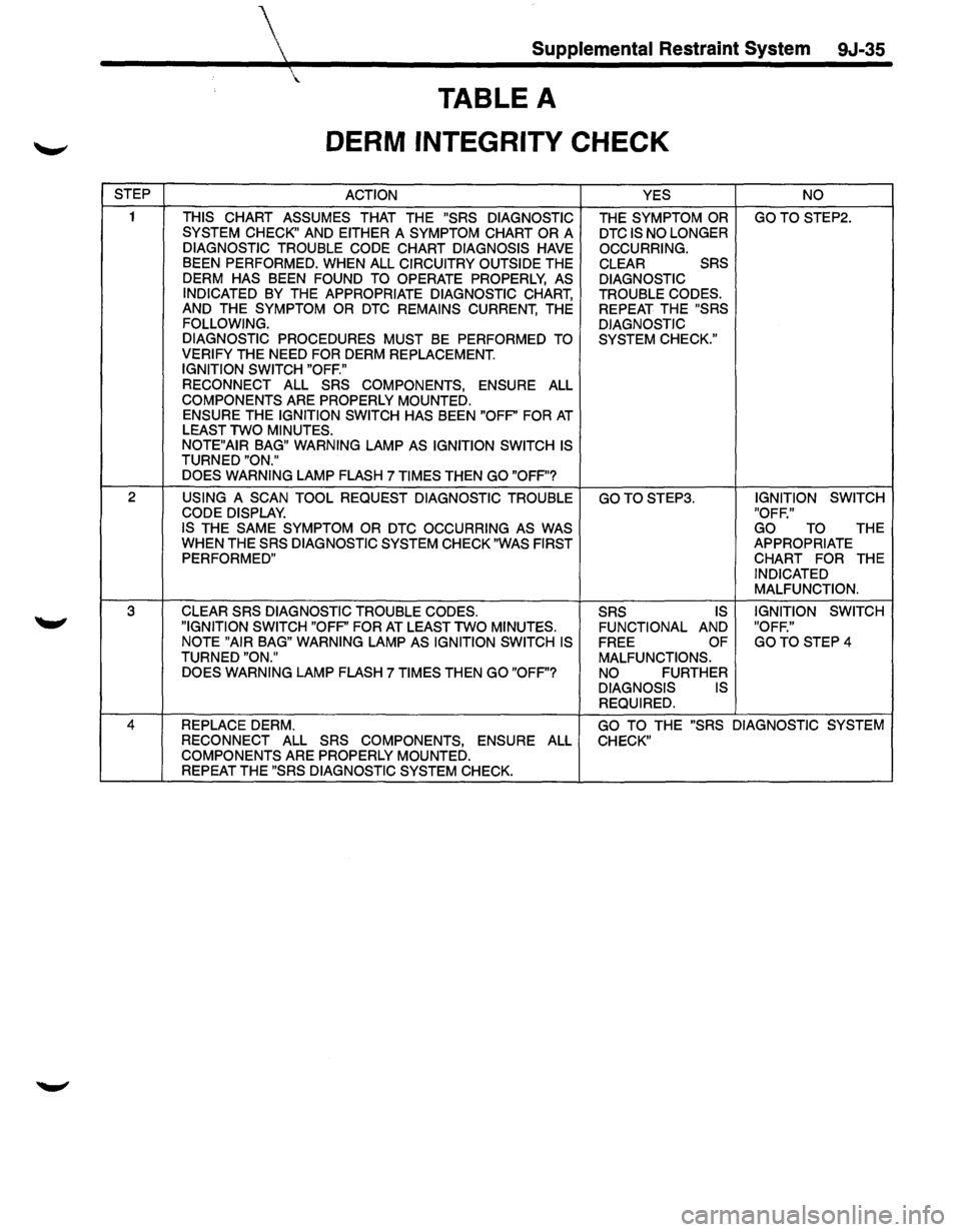
STEP
2
3
Supplemental Restraint System 9J-35
TABLE A
DERM INTEGRITY CHECK
ACTION
THIS
CHART ASSUMES THAT THE "SRS DIAGNOSTIC
SYSTEM CHECK" AND EITHER A SYMPTOM CHART OR A
DIAGNOSTIC TROUBLE CODE CHART DIAGNOSIS HAVE BEEN PERFORMED. WHEN ALL CIRCUITRY OUTSIDE THE
DERM HAS BEEN FOUND TO OPERATE PROPERLY, AS
INDICATED BY THE APPROPRIATE DIAGNOSTIC CHART, AND THE SYMPTOM OR DTC REMAINS CURRENT, THE FOLLOWING.
DIAGNOSTIC PROCEDURES MUST BE PERFORMED TO VERIFY THE NEED FOR DERM REPLACEMENT. IGNITION SWITCH "OFF."
RECONNECT
ALL SRS COMPONENTS, ENSURE ALL
COMPONENTS ARE PROPERLY MOUNTED.
ENSURE THE IGNITION SWITCH HAS BEEN "OFP' FOR AT LEAST TWO MINUTES.
NOTE"AIR BAG" WARNING LAMP AS IGNITION SWITCH IS TURNED "ON."
DOES WARNING LAMP FLASH 7 TIMES THEN GO "OFF"?
USING
A SCAN TOOL REQUEST DIAGNOSTIC TROUBLE CODE DISPLAY. IS THE SAME SYMPTOM OR DTC OCCURRING AS WAS WHEN THE SRS DIAGNOSTIC SYSTEM CHECK "WAS FIRST
PERFORMED"
CLEAR SRS DIAGNOSTIC TROUBLE CODES.
"IGNITION SWITCH "OFP' FOR AT LEAST TWO MINUTES.
NOTE "AIR BAG" WARNING LAMP AS IGNITION SWITCH IS TURNED "ON."
DOES WARNING LAMP FLASH 7 TIMES THEN GO "OFF"? YES
THE SYMPTOM OR DTC IS NO LONGER
OCCURRING. CLEAR SRS
DIAGNOSTIC
TROUBLE CODES. REPEAT THE "SRS
DIAGNOSTIC SYSTEM CHECK."
GOTOSTEP3.
SRS IS
FUNCTIONAL AND
FREE OF
MALFUNCTIONS.
NO FURTHER DIAGNOSIS IS REQUIRED. NO
GOTO STEP2.
IGNITION
SWITCH
"OFF." GO
TO THE APPROPRIATE CHART FOR THE INDICATED MALFUNCTION.
IGNITION SWITCH
"OFF."
GOTO STEP4
4 REPLACE DERM. GO TO THE "SRS DIAGNOSTIC SYSTEM
RECONNECT ALL SRS COMPONENTS, ENSURE ALL CHECK"
COMPONENTS ARE PROPERLY MOUNTED.
REPEAT THE "SRS DIAGNOSTIC SYSTEM CHECK.
Page 1660 of 1928
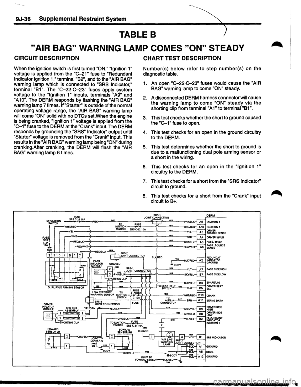
9J-36 Supplemental Restraint System
TABLE B
"AIR BAG" WARNING LAMP COMES "ON" STEADY
CIRCUIT DESCRIPTION
When the ignition switch is first turned "ON," "Ignition 1"
voltage is applied from the "C-21" fuse to "Redundant
Indicator Ignition 1 ,"terminal "B2", and to the "AIR BAG"
warning lamp which is connected to "SRS Indicator,"
terminal "B1". The "C-22·C-23" fuses apply system
voltage to the
"Ignition 1" inputs, terminals "A9" and
"A10". The DERM responds by flashing the "AIR BAG"
warning lamp 7 times. If "Starter" is outside of the normal
operating voltage range, the
"AIR BAG" warning lamp
will
come "ON" solid with no DTCs set. When the engine
is being cranked,
"Ignition 1" voltage is applied from the
"C-1" fuse to the DERM at the "Crank" input. The DERM
responds by grounding the
"SRS" Indicator" output until
"Starter" voltage is removed from the "Crank'' input. This
results in the
"AIR BAG" warning lamp being "ON" during
cranking.After cranking, the DERM
will flash the "AIR
BAG" warning lamp 6 times.
CHART TEST DESCRIPTION
Number(s) below refer to step number(s) on the
diagnostic table.
1. An open "C-22-C-23" fuses would cause the "AIR
BAG" warning lamp to come "ON" steady.
2. A disconnected DERM harness connector will cause
the warning
lamp to come "ON" steady via the
shorting clip from terminal "A1" to terminal "81".
3. This test checks whether the short to ground caused
the
"C-1" fuse to open.
4. This test checks for an open in the ground circuitry
to the DERM.
5. This test determines whether the short to ground is
due to a malfunctioning dual pole arming sensor or
a short
in the wiring.
6. This test checks for an open in the "Ignition 1"
circuitry to the DERM.
7. This test checks for a short from the "SRS Indicator''
circuit to ground.
8. This test checks for a short from the "Crank" input
circuit to 8+.
SRS-1 JOINT CONNECTION TO IGNITION FUSE SRS C·23 10A 1!015 '12 10 IGNITION I IGNITION 1 SWITCH
FUSE~ SRS C-24 10A .... R D
PASS.3eVLR PASS. SOURCE SENSE
PASS SlOE HIGH
PASS SlOE LOW
SERIAL DATA
SRS INDICATOR
..