jump start ISUZU TROOPER 1995 User Guide
[x] Cancel search | Manufacturer: ISUZU, Model Year: 1995, Model line: TROOPER, Model: ISUZU TROOPER 1995Pages: 1928
Page 733 of 1928
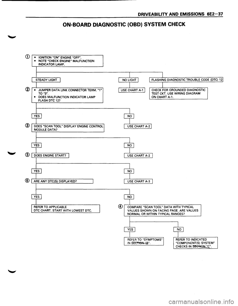
DRIVEABILITY AND EMISSIONS 6E2-37
ON-BOARD DIAGNOSTIC (OBD) SYSTEM CHECK
(j) • IGNITION "ON" ENGINE "OFF".
• NOTE "CHECK ENGINE" MALFUNCTION INDICATOR LAMP.
STEADY LIGHT
@ • JUMPER DATA LINK CONNECTOR TERM. "1" TO "3".
• DOES MALFUNCTION INDICATOR LAMP FLASH DTC 127
@ DOES "SCAN TOOL" DISPLAY ENGINE CONTROL MODULE DATA?
REFER TO APPLICABLE DTC CHART. START WITH LOWEST DTC.
CHECK FOR GROUNDED DIAGNOSTIC TEST CKT. USE WIRING DIAGRAM ON CHART A-1.
@ COMPARE "SCAN TOOL" DATA WITH TYPICAL VALUES SHOWN ON FACING PAGE. ARE VALUES NORMAL OR WITHIN TYPICAL RANGES?
REFER TO INDICATED "COMPONENT(S) SYSTEM" CHECKS IN~·.
Page 747 of 1928
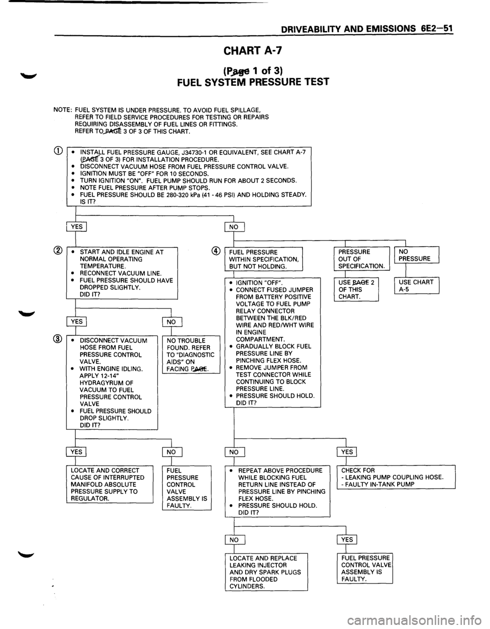
DRIVEABILITV AND EMISSIONS 6E2-51
CHART A-7
(PJtge 1 of 3}
FUEL SYSTEM PRESSURE TEST
NOTE: FUEL SYSTEM IS UNDER PRESSURE. TO AVOID FUEL SPILLAGE, REFER TO FIELD SERVICE PROCEDURES FOR TESTING OR REPAIRS
REQUIRING DISASSEMBLY OF FUEL LINES OR FITTINGS. REFER TO~ 3 OF 3 OF THIS CHART.
CD • INSTALL FUEL PRESSURE GAUGE, J34730-1 OR EQUIVALENT, SEE CHART A-7 ~3 OF 3) FOR INSTALLATION PROCEDURE.
• DISCONNECT VACUUM HOSE FROM FUEL PRESSURE CONTROL VALVE.
• IGNITION MUST BE "OFF" FOR 10 SECONDS.
• TURN IGNITION "ON". FUEL PUMP SHOULD RUN FOR ABOUT 2 SECONDS.
• NOTE FUEL PRESSURE AFTER PUMP STOPS.
• FUEL PRESSURE SHOULD BE 280-320 kPa (41-46 PSI) AND HOLDING STEADY. IS IT?
I
• START AND IDLE ENGINE AT NORMAL OPERATING TEMPERATURE. • RECONNECT VACUUM LINE.
• FUEL PRESSURE SHOULD HAVE
DROPPED SLIGHTLY.
DID IT?
I
@ FUEL PRESSURE
WITHIN SPECIFICATION,
BUT NOT HOLDING.
• IGNITION "OFF".
.---'---$YES
-$r---'--NO -
@ • DISCONNECT VACUUM NO TROUBLE •
CONNECT FUSED
JUMPER FROM BATTERY POSITIVE
VOLTAGE TO FUEL PUMP
RELAY CONNECTOR BETWEEN THE BLK/RED WIRE AND RED/WHT WIRE IN ENGINE
COMPARTMENT.
HOSE FROM
FUEL FOUND. REFER PRESSURE CONTROL TO "DIAGNOSTIC
VALVE. AIDS" ON
• WITH ENGINE IDLING. FACING P.A@f. APPLY 12-14"
HYDRAGYRUM OF VACUUM TO FUEL PRESSURE CONTROL
VALVE
•
FUEL PRESSURE SHOULD DROP SLIGHTLY.
DID IT?
I
• GRADUALLY BLOCK FUEL PRESSURE LINE BY PINCHING FLEX HOSE.
• REMOVE JUMPER FROM
TEST CONNECTOR WHILE
CONTINUING TO BLOCK
PRESSURE LINE.
• PRESSURE SHOULD HOLD.
DID
IT?
I PRESSURE
OUT OF SPECIFICATION.
I USE,.eAef 2 OF THIS CHART.
I
INO I PRESSURE
I
I USE CHART I A-5
~~NLO------------------~ $~YELS---------------------, LOCATE AND CORRECT
CAUSE OF INTERRUPTED
MANIFOLD ABSOLUTE
PRESSURE SUPPLY TO
REGULATOR. FUEL PRESSURE
CONTROL VALVE ASSEMBLY
IS FAULTY.
• REPEAT ABOVE PROCEDURE CHECK FOR WHILE BLOCKING FUEL -LEAKING PUMP COUPLING HOSE. RETURN LINE INSTEAD OF -FAUL TV IN-TANK PUMP PRESSURE LINE BY PINCHING FLEX HOSE.
• PRESSURE SHOULD HOLD.
DID
IT?
LOCATE AND REPLACE LEAKING INJECTOR AND DRY SPARK PLUGS
FROM FLOODED
CYLINDERS.
FUEL PRESSURE
CONTROL VALVE
ASSEMBLY
IS FAULTY.
Page 748 of 1928
6E2-52 DRIVEABILITV AND EMISSIONS
CHART A-7
(Page 2 of 3)
FUEL SYSTEM PRESSURE TEST
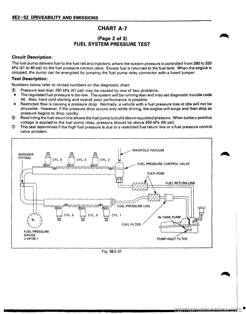
Circuit Description:
The fuel pump delivers fuel to the fuel rail and injectors, where the system pressure is controlled from 280 to 320
kPa (41 to 46 psi) by the fuel pressure control valve. Excess fuel is returned to the fuel tank. When the engine is
stopped, the
pump can be energized by jumping the fuel pump relay connector with a fused jumper.
Test Description:
Numbers below refer to circled numbers on the diagnostic chart.
® Pressure less than 280 kPa (41 psi) may be caused by one of two problems.
• The regulated fuel pressure is too low. The system will be running lean and may set diagnostic trouble code
44. Also, hard cold starting and overall poor performance is possible.
• Restricted flow is causing a pressure drop. Normally, a vehicle with a fuel pressure loss at idle will not be
driveable. However,
if the pressure drop occurs only while driving, the engine will surge and then stop as
pressure begins to drop rapidly.
® Restricting the fuel return line allows the fuel pump to build above regulated pressure. When battery positive
voltage is applied to the fuel pump relay, pressure should
be above 450 kPa (65 psi).
® This test determines if the high fuel pressure is due to a restricted fuel return line or a fuel pressure control
valve problem.
SHRADER FITIING
FUEL PRESSURE GAUGE J-34730-1
Fig. 6E2-31
MANIFOLD VACUUM
FUEL PRESSURE CONTROL VALVE
FUEL RETURN
LINE
FUEL FILTER
PUMP INLET FILTER
•
Page 839 of 1928
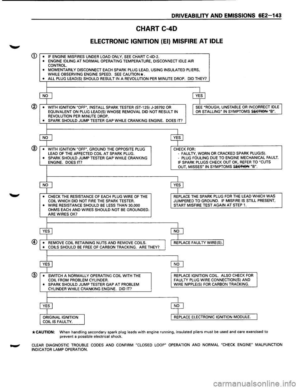
DRIVEABILITV AND EMISSIONS 6E2-143
CHART C-40
ELECTRONIC IGNITION (EI) MISFIRE AT IDLE
CD • IF ENGINE MISFIRES UNDER LOAD ONLY, SEE CHART C-4D-2. • ENGINE IDLING AT NORMAL OPERATING TEMPERATURE, DISCONNECT IDLE AIR CONTROL. • MOMENTARILY DISCONNECT EACH SPARK PLUG LEAD, USING INSULATED PLIERS,
WHILE OBSERVING ENGINE SPEED. SEE CAUTION*. • ALL PLUG LEAD(S) SHOULD RESULT IN A REVOLUTION PER MINUTE DROP. DID THEY?
$ $
•
WITH IGNITION "OFF", INSTALL SPARK TESTER (ST-125) J-26792 OR I SEE "ROUGH, UNSTABLE OR INCORRECT IDLE
EQUIVALENT ON PLUG LEAD(S) WHOSE REMOVAL DID NOT RESULT IN OR STALLING" IN SYMPTOMS Si€'FISN "B". REVOLUTION PER MINUTE DROP. • SPARK SHOULD JUMP TESTER GAP WHILE CRANKING ENGINE. DOES IT?
$ $
•
WITH IGNITION "OFF", GROUND THE OPPOSITE PLUG CHECK FOR: @
LEAD OF THE AFFECTED COIL AT SPARK PLUG. -
FAUL TV, WORN OR CRACKED SPARK PLUG(S). • SPARK SHOULD JUMP TESTER GAP WHILE CRANKING -PLUG FOULING DUE TO ENGINE MECHANICAL FAULT. ENGINE. DOES IT? IF SPARK PLUGS CHECK OUT OK, REFER TO "CUTS
OUT, MISSES" IN SYMPTOMS SiC'flet~ "B".
~ $
• CHECK THE RESISTANCE OF EACH PLUG WIRE OF THE REPLACE
THE SPARK PLUG FOR THE LEAD WHICH WAS COIL WHICH DID NOT FIRE THE SPARK TESTER. JUMPERED TO GROUND. IF MISFIRE
IS STILL PRESENT, • WIRE RESISTANCE SHOULD BE LESS THAN 30,000 START MISFIRE TEST AGAIN AT STEP 1. OHMS EACH AND WIRES SHOULD NOT BE GROUNDED.
ARE WIRES OK?
$ $
• REMOVE COIL RETAINING NUTS AND REMOVE COILS.
I
REPLACE FAUL TV WIRE(S).I
• COILS SHOULD BE FREE OF CARBON TRACKING. ARE THEY?
$ $
•
SWITCH A NORMALLY OPERATING COIL WITH THE REPLACE IGNITION
COIL. ALSO CHECK FOR COIL FROM PROBLEM CYLINDER. FAULTY PLUG WIRE CONNECTION(S) AND • SPARK SHOULD JUMP TESTER GAP AT PROBLEM WIRE NIPPLE(S) FOR CARBON TRACKING.
CYLINDER WHILE CRANKING ENGINE. DID IT?
$ $
ORIGINAL IGNITION
I
REPLACE ELECTRONIC IGNITION MODULE. COIL IS FAUL TV.
*CAUTION: When handling secondary spark plug leads with engine running, insulated pliers must be used and care exercised to
prevent a possible electrical shock.
CLEAR DIAGNOSTIC TROUBLE CODES AND CONFIRM "CLOSED LOOP" OPERATION AND NORMAL "CHECK ENGINE" MALFUNCTION
INDICATOR LAMP OPERATION.
Page 841 of 1928
DRIVEABILITV AND EMISSIONS 6E2-145
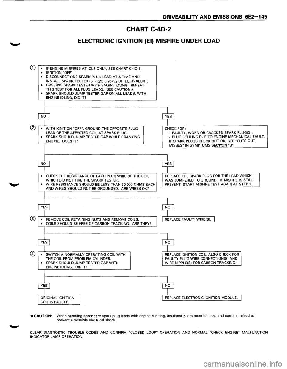
CHART C-40-2
ELECTRONIC IGNITION (EI) MISFIRE UNDER LOAD
CD • IF ENGINE MISFIRES AT IDLE ONLY, SEE CHART C-4D-1. • IGNITION "OFF"
• DISCONNECT ONE SPARK PLUG LEAD AT A TIME AND,
INSTALL SPARK TESTER (ST-125) J-26792 OR EQUIVALENT.
• OBSERVE SPARK TESTER WITH ENGINE IDLING. REPEAT THIS TEST FOR ALL PLUG LEADS. SEE CAUTION* • SPARK SHOULD JUMP TESTER GAP ON ALL LEADS, WITH
ENGINE IDLING, DID IT?
~ $
• WITH IGNITION "OFF", GROUND THE OPPOSITE PLUG CHECK FOR: LEAD OF THE AFFECTED COIL AT SPARK PLUG. -
FAUL TV, WORN OR CRACKED SPARK PLUG(S). • SPARK SHOULD JUMP TESTER GAP WHILE CRANKING -PLUG FOULING DUE TO ENGINE MECHANICAL FAULT. ENGINE. DOES IT? IF SPARK PLUGS CHECK OUT OK, SEE "CUTS OUT,
MISSES" IN SYMPTOMS SEe'l'tO'I'Q' "B".
~ $
• CHECK THE RESISTANCE OF EACH PLUG WIRE OF THE COIL REPLACE THE SPARK PLUG FOR THE LEAD WHICH
WHICH DID NOT FIRE THE SPARK TESTER. WAS JUMPERED TO GROUND. IF MISFIRE IS STILL
• WIRE RESISTANCE SHOULD BE LESS THAN 30,000 OHMS EACH PRESENT, START MISFIRE TEST AGAIN AT STEP 1. AND WIRES SHOULD NOT BE GROUNDED. ARE WIRES OK?
~ $
• REMOVE COIL RETAINING NUTS AND REMOVE COILS. REPLACE FAUL TV WIRE(S). I ® • COILS SHOULD BE FREE OF CARBON TRACKING. ARE THEY?
$ $
• SWITCH A NORMALLY OPERATING COIL WITH REPLACE IGNITION COIL. ALSO CHECK FOR THE COIL FROM PROBLEM CYLINDER. FAUL TV PLUG WIRE CONNECTION(S) AND • SPARK SHOULD JUMP TESTER GAP WITH WIRE
NIPPLE(S) FOR CARBON TRACKING.
ENGINE IDLING. DID IT?
:r ~ ORIGINAL IGNITION
I
REPLACE ELECTRONIC IGNITION MODULE. COIL IS FAUL TV.
*CAUTION: When handling secondary spark plug leads with engine running, insulated pliers must be used and care exercised to prevent a possible electrical shock.
CLEAR
DIAGNOSTIC TROUBLE CODES AND CONFIRM "CLOSED LOOP" OPERATION AND NORMAL "CHECK ENGINE" MALFUNCTION
INDICATOR LAMP OPERATION.
Page 1632 of 1928
9J-8 Supplemental Restraint System
DEFINITIONS
AIR BAG -An inflatable cloth cushion designed to
deploy in certain frontal crashes. It supplements the
protection offered by the seat belts by distributing the
impact load more evenly over the vehicle occupant's
head and torso.
ASYNCHRONOUS -Performed in a non-periodic
fashion,i.e.no defined time or interval.
B+-Battery voltage, the voltage available at the battery
at the time of the indicated measurement. With the key
"ON" and the engine not running, the system voltage will
likely be between 12 and 12.5 volts. At idle the voltage
may be 14 to 16 volts. The voltage could be as low as 1
0
volts during engine cranking.
BULB
CHECK-The DERM will cause the "AIR BAG"
warning lamp to flash seven times and then go "OFF"
whenever the ignition switch transitions to the RUN
position from any other ignition switch position and no
malfunctions are detected.
"CONTINUOUS MONITORING"-Tests performed by
the DERM on the
SRS every 1 00 milliseconds while
"Ignition
1" voltage is in the normal operating voltage
range at the DERM.
DATA LINK CONNECTOR(DLC)-Formerly "ALDL'', a
connector which allows communication with an
off-board computer, such as a scan
tool.
DATUM LINE-A base line parallel to the plane of the
underbody or frame from which all vertical
measurements originate.
DEPLOY-To inflate the air bag.
DEPLOYMENT
LOOPS - The circuits which supply
current to the inflator modules to deploy the air bag.
DERM -Diagnostic
energy reserve module which
provides reserve energy to the deployment loops and
performs diagnostic monitoring of
all SRS components.
DIAGNOSTIC TROUBLE CODE(DTC) -Formerly
"Code,"a numerical designator used by the DERM to
indicate specific
SRS malfunctions.
DRIVER CURRENT SOURCE-An output of the DERM
which injects current into the driver inflator module circuit
during the "Initiator Assembly Resistance
Test."
DRIVER INFLATOR
MODULE-An assembly located in
the steering wheel hub consisting of an inflatable air bag,
an inflator and an initiator.
DUAL
POLE ARMING SENSOR-A sensor on the high
side(power side) of the deployment loops that is
calibrated to supply voltage to the inflator modules when
the vehicle velocity changes are severe enough to
warrant arming of the air bags in preparation for
deployment.
EEPROM -Electrically Erasable Programmable Read ~
Only Memory. Memory which retains its contents when
power
is removed from the DERM.
FORWARD LH DISCRIMINATING SENSOR-A sensor
on the low side(ground side) of the deployment loops
which is calibrated to ground the inflator modules when
the vehicle velocity changes are severe enough to
warrant deployment of the air bags.
FORWARD RH DISCRIMINATING SENSOR-A sensor
on the low side(ground side) of the deployment loops
which
is calibrated to ground the inflator modules when
the vehicle velocity changes are severe enough
to
warrant deployment of the air bag.
FORWARD LH SENSOR Eng-Room HARNESS-An
assembly of two correct carrying wires which connects
the Forward
LH discriminating sensor to SRS harness.
FORWARD RH SENSOR Eng-Room HARNESS
JUMPER-An assembly of two current carrying wires
which connects the Forward
RH discriminating sensor to
the
SRS harness.
HIGHER PRIORITY FAULT-Each diagnostic trouble
code
is assigned a priority based on the detectability with
other DTCs present. The priority corresponds to the
detectability of the malfunction ONLY, and does NOT
relate to the criticality of the malfunction with respect to ~
deployment or non-deployment under any given
condition.
IGNITION CYCLE -The voltage at the PERM "Ignition
1"
inputs, with ignition switch "ON," is within the normal
operating voltage range for at least ten seconds before
turning ignition switch
"OFF."
IGNITION1
-A battery voltage(B+)circuit which is only
powered with the ignition switch in the RUN,BULB
TEST,or START positions.
INITIATOR-The electrical component inside the inflator
module which, when sufficient current flows, sets off the
chemical reaction that inflates the air bag.
"INITIATOR ASSEMBLY RESISTANCE TEST"-Tests
performed once each ignition cycle when no
malfunctions are detected during "Turn-ON" or
"Continuous Monitoring." This test checks for the correct
DERM configuration for the vehicle, shorts to
"Ignition 1"
in the deployment loops, high resistance or opens in the
"Driver
Side High," "Driver Side Low," "Passenger Side
High"
and "Passenger Side Low" circuits and measures
the resistance of the inflator assembly consisting of: 1)
Initiators, 2) SRS coil assembly(driver side only), 3)
Connectors and associated wiring.
NORMAL OPERATING VOLTAGE RANGE-The ~
voltage measured between the DERM "Ignition 1" ·
terminals and "Ground" terminals is between 7.25 and 16
volts.
•
Page 1642 of 1928
9J-18 Supplemental Restraint System
NOTE: Ensure that the pigtail adapter is firmly seated
into the driver inflator module connector. Failure to fully
seat the connectors may leave the shorting bar located
in the
driver inflator module connector functioning
(shorted) and may result
in non-deployment of the driver
inflator module.
12. Verify that the area around the driver inflator module
is clear of all people and loose or flammable objects.
13. Verify that the driver inflator module is resting with its
trim cover facing up.
14. Notify all people
in the immediate area that you
intend to deploy the driver inflator module. The
deployment will be accompanied by a loud noise
which may startle the uninformed.
15.
Separate the two banana plugs on the SRS
deployment harness.
NOTE: When the air bag deploys, the driver inflator
module may jump about
30 em (one foot) vertically. This
is a normal reaction of the driver inflator module to the
force of the rapid gas expansion inside the air bag.
NOTE: When the air bag deploys, the rapid gas
expansion will create a loud noise. Notify all people
in the
immediate area that you intend to deploy the driver
inflator module.
16. Connect the
SRS deployment harness wires to the
power source to immediately deploy the driver
inflator module. Recommended application: 12 volts
minimum, 2 amps minimum. A vehicle battery is
suggested.
17. Disconnect the
SRS deployment harness from the
power source.
18.
Short the two SRS deployment harness leads
together by fully seating one banana plug into the
other.
19.
In the unlikely event that the driver inflator module did
not deploy after following these procedures, proceed
immediately with
Steps 24 through 27. If the driver
inflator module did deploy, proceed with
Steps 20
through 23.
20. Put on a pair of shop gloves to protect your hands
from possible irritation and heat when handling the
deployed driver inflator module.After the driver
inflator module has been deployed, the surface of the
air bag may contain a powdery residue. This power
consists primarily of cornstarch(used to lubricate the
bag as it inflates) and byproducts of the chemical
reaction.
Sodium hydroxide dust( similar to lye soap)
is produced as a byproduct
of the deployment
reaction.The sodium hydroxide then quickly reacts
with the atmospheric moisture and is converted to
sodium carbonate and sodium bicarbonate(baking
soda). Therefore, it is unlikely that sodium hydroxide
will be present after deployment. As a precaution,
however, gloves and safely glasses are
recommended to prevent any possible irritation of
the skin or eyes.
WARNING: SAFETY PRECAUTIONS MUST BE
OBSERVED WHEN
HANDING A DEPLOYED
INFLATOR MODULE. AFTER DEPLOYMENT, THE ~
METAL SURFACES OF THE INFLATOR MODULE
WILL BE VERY HOT. ALLOW THE INFLATOR
MODULE TO COOL BEFORE HANDLING ANY
METAL PORTION OF IT. DO NOT PLACE THE
DEPLOYED
INFLATOR MODULE NEAR ANY
FLAMMABLE OBJECTS.
FAILURE TO FOLLOW
PROCEDURES MAY RESULT
IN FIRE OR
PERSONAL INJURY.
After a driver inflator module has been deployed, the
metal canister and surrounding areas
of the driver
inflator module will
be very hot. Do not touch the metal
areas of the driver inflator module for about twenty
minutes after deployment.
If the deployed driver inflator
module must
be moved before it is cool, wear gloves and
handle by the air bag or trim cover.
21. Disconnect the pigtail adapter from the driver inflator
module as soon after deployment as possible. This
will prevent damage to the pigtail adapter or
SRS
deployment harness due to possible contact with the
hot driver inflator module canister. The pigtail can be
reused. They should, however, be inspected for
damage after each deployment and replaced if
necessary.
22. Dispose of the deployed driver inflator module
through normal refuse channels after it has cooled
for at least
20 minutes. ~
23. Wash your hands with mild soap and water
afterward.
NOTE: The remaining steps are to be followed in the
unlikely event that the driver inflator module did not
deploy after following these procedures.
24. Ensure that the
SRS deployment harness has been
disconnected from the power source and that its two
banana plugs have been shorted together by fully
seating one banana plug into the other.
25. Disconnect the pigtail
adapter from the driver inflator
module.
WARNING: WHEN STORING A LIVE INFLATOR
MODULE OR WHEN LEAVING A LIVE INFLATOR
MODULE UNATTENDED ON A BENCH OR OTHER
SURFACE, ALWAYS FACE THE BAG AND
TRIM
COVER
UP AND AWAY FROM THE SURFACE. THIS
IS
NECESSARY SO THAT A FREE SPACE
ISRPROVIDED TO ALLOW THE AIR BAG TO
EXPAND IN THE UNLIKELY EVENT OF ACCIDENTAL
DEPLOYMENT. FAILURE TO FOLLOW
PROCEDURES MAY RESULT IN PERSONAL
INJURY.
•
Page 1647 of 1928
15. Strip 13 mm(1/2 inch) of insulation from each wire
lead of the connector.
16.
Cut two 900 cm(30 feet) deployment wires from
0.8mm2(18 gauge) or thicker multi-strand wire.
These wires
will be used to fabricate the passenger
deployment harness.
17.
Strip 13 mm {1/2inch)of insulation from both ends of
the wires cut in the previous step.
18.
Short the wires by twisting together one end from
each.
Deployment wires shall remain shorted and
not be connected to a power source
until the air bag
is to be deployed.
WARNING: FAILURE TO FOLLOW
PROCEDURES
IN THE ORDER LISTED COULD RESULT IN
PERSONAL INJURY. NEVER CONNECT
DEPLOYMENT WIRES TO ANY POWER SOURCE
BEFORE CONNECTING DEPLOYMENT WIRES TO
THE INFLATOR MODULE LEADS. DEPLOYMENT
WIRES SHALL REMAIN SHORTED AND NOT BE
CONNECTED TO A POWER SOURCE UNTIL THE
AIR BAG IS DEPLOYED? THE INFLATOR MODULE
WILL IMMEDIATELY DEPLOY THE AIR BAG WHEN
A POWER
SOURCE IS CONNECTED TO IT. WEAR
SAFETY GLASSES THROUGHOUT THIS ENTIRE
DEPLOYMENT AND DISPOSAL PROCEDURE.
19. Twist
together one connector wire lead to one
deployment wire. The connection should be
mechanically secure.
20. Bend twisted connection made in the previous step
flat and wrap tightly with electrical tape to insulate
and secure.
21.
Twist together, bend and tape the remaining
connector wire lead to the remaining deployment
wire.
22. Connect the
deployment harness to the passenger
inflator module jumper, yellow 2-way connector
located behind the 1/P compartment door assembly.
Route deployment harness out the passenger side of
the
vehicle.
WARNING:
DEPLOYMENT WIRES SHALL REMAIN
SHORTED
AND NOT BE CONNECTED TO A POWER
SOURCE UNTIL THE AIR BAG IS TO BE DEPLOYED.
THE INFLATOR MODULE WILL IMMEDIATELY
DEPLOY THE AIR BAG WHEN A POWER SOURCE IS
CONNECTED TO IT. CONNECTING THE
DEPLOYMENT WIRES SHOULD ALWAYS BE THE
FINAL STEP IN THE INFLATOR MODULE
DEPLOYMENT PROCEDURE. FAILURE TO
FOLLOW PROCEDURES IN THE ORDER LISTED
COULD RESULT IN PERSONAL INJURY.
23. Verify that the inside of the vehicle and the area
surrounding the
vehicle are clear of all people and
loose or flammable objects.
24.
Stretch the driver and passenger deployment
harnesses to their full length.
Supplemental Restraint System 9J-23
. Completely cover windshield area and front door
window openings with a drop
cloth, blanket or similar
item. This reduced the possibility of injury due to
possible fragmentation of the vehicle's glass or
interior.
26. Notify
all people in the immediate area that you
intend to
deploy the air bags. The deployment will be
accompanied by a
loud noise which may startle the
uninformed.
27.
Separate the two ends of the driver deployment
harness wires.
WARNING: DEPLOYMENT WIRES SHALL REMAIN
SHORTED
AND NOT BE CONNECTED TO A POWER
SOURCE UNTIL THE AIR BAG IS TO BE DEPLOYED.
THE INFLATOR MODULE WILL IMMEDIATELY
DEPLOY THE AIR BAG WHEN A POWER SOURCE IS
CONNECTED TO IT. CONNECTING THE
DEPLOYMENT WIRES TO THE POWER SOURCE
SHOULD ALWAYS BE THE FINAL STEP IN THE
INFLATOR MODUL,E DEPLOYMENT PROCEDURE.
FAILURE TO FOLLOW PROCEDURES IN THE
ORDER LISTED COULD RESULT IN PERSONAL
INJURY.
NOTE: When the air bag deploys, the rapid gas
expansion will create a loud noise. Notify all people in the
immediate area that you intend to
deploy the air bags.
28. Connect the driver
deployment harness wires to a
power source to immediately deploy the driver
inflator module. Recommended application: 12 volts
minimum, 2 amps minimum. A vehicle battery is
suggested.
29.
Separate the two ends of the passenger deployment
harness wires.
WARNING: DEPLOYMENT WIRES SHALL REMAIN
SHORTED
AND NOT BE CONNECTED TO A POWER
SOURCE UNTIL THE AIR BAG IS TO BE DEPLOYED.
THE INFLATOR MODULE WILL IMMEDIATELY
DEPLOY THE AIR BAG WHEN A POWER SOURCE IS
CONNECTED TO IT. CONNECTING THE
DEPLOYMENT WIRES TO THE POWER SOURCE
SHOULD ALWAYS BE THE FINAL STEP IN THE
INFLATOR MODULE DEPLOYMENT PROCEDURE.
FAILURE TO FOLLOW PROCEDURES IN THE
ORDER LISTED COULD RESULT IN PERSONAL
INJURY.
30.
Connectthe passenger deployment harness wires to
a power source to
immediately deploy the passenger
inflator module. Recommended application: 12 volts
minimum, 2 amps minimum. A vehicle battery is
suggested.
After
an inflator module has been deployed, the
surface of the air bag may contain a powdery
residue. This powder consists primarily of cornstarch
(used to lubricate the bag as it inflates) and
byproducts of the chemical reaction. Sodium
hydroxide dust (similar to lye soap) is produced as a
byproduct of the
deployment reaction. The sodium