seats ISUZU TROOPER 1995 Workshop Manual
[x] Cancel search | Manufacturer: ISUZU, Model Year: 1995, Model line: TROOPER, Model: ISUZU TROOPER 1995Pages: 1928
Page 5 of 1928
GENERAL INFORMATION OA-1
GENERAL INFORMATION
CONTENTS
General Information ........................................................ /.. . . . . . . . . Section OA / Maintenance and Lubrication ............................................. ~·. . . . . . . . . . . . . Section 08
SECTION OA
GENERAL INFORMATION
CONTENTS
General repair instructions ...................... OA-1 Standard bolts torque
specifications .......... OA-9
How to use this manual. ......................... OA-2 Abbreviations
charts ............................. OA-10
Identification
....................................... OA-5 Service
parts identification plate ............... OA-12
Lifting instructions ................................ OA-7
GENERAL REPAIR INSTRUCTIONS
1. If a floor jack is used, the following precautions
are recommended.
Park
vehicle on level ground, "block" front or
rear wheels, set jack against the recommended
lifting points (see "Lifting instructions" in this
section), raise
vehicle and support with chassis
stands and then perform service operations.
2. Before performing service operations, disconnect
ground
cable from the battery to reduce the
chance
of cable damage and burning due to
short circuiting.
3. Use a cover on body, seats and floor to protect
them against damage and contamination.
4. Brake fluid and anti-freeze solution must be
handled with reasonable care, as they can cause
paint damage.
5. The use of proper tools and recommended
essential and available tools, where specified, is
important for efficient and reliable performance
of service repairs.
6. Use genuine lsuzu parts.
7. Used cotter pins, plastic clips, gaskets, 0-rings,
oil seals, lock washers and self-locking nuts
should be discarded and new ones should be
installed, as normal function of the parts cannot
be maintained
if these parts are reused.
8. To facilitate proper and smooth reassembly
operation, keep disassembled parts neatly in
groups. Keeping fixing
bolts and nuts separate
is
very important, as they vary in hardness and
design depending on position
of installation.
9. Clean the parts before inspection or reassembly.
Also clean oil
ports, etc. using compressed air,
and make certain
they are free from restrictions.
10. Lubricate rotating and sliding faces of the parts
with oil or grease before installation.
11. When necessary, use a sealer on gaskets to pre
vent leakage.
12. Carefully observe all specifications for bolt and
nut torques.
13. When removing or replacing parts that require
refrigerant
to be discharged from the air
conditioning system, be sure
to use the Vehicle
Refrigerant Recovery and Recycling Equipment
(VRRRE) to recover and recycle Refrigerant-
134a.
14. When a service operation is completed, make a
final check to be sure the service has been done
properly and the problem has been corrected.
Page 207 of 1928
WHEELS AND TIRES 3E-1
TIRES
REPLACEMENT
UNIT REPAIR
WHEELS
REPLACEMENT
When replacement is necessary, the original metric
the size should be used. Most metric tire sizes do not
have exact corresponding alphanumeric tire sizes. It
is recommended that new tires be installed in pairs on
the same axle. If necessary to replace only one tire, it
should be paired with tire having the most tread, to
equalize braking traction.
w CAUTION:
Do not mix different types of tires such as radial,
bias and bias-belted tires except in emergencies,
because
vehicle handling may be seriously
affected and may result in loss of control.
TIRE DISMOUNTING
Remove valve cap on valve step and deflate the tire.
Then use a
tire changing machine to mount or
dismount tires.
Follow the equipment manufacturer's instruction. Do
not use hand tools or tire lever alone to change tires
as they may damage the tire beads or wheel rim.
TIRE MOUNTING
Rim bead seats should be cleaned with a wire brush
....._., or coarse steel wool to remove lubricants, and light
rust. Before mounting a tire, the bead area should be
well lubricated with an approved tire lubricant.
After mounting, inflate the tire to 196kPa (28 psi) so
that beads are completely seated. Inflate the air to
specified pressure and install valve cap to the stem.
\f WARNING:
Never stand over tire when inflating. Bead may
break when bead snaps over rim's safety hump
and cause serious personal injury.
Never exceed
240 kPa (35 psi) pressure when
inflating. If 240 kPa (35 psi) pressure will not
seat beads, deflate, re-lubricate and re-inflate.
Over
inflation may cause the bead to break and
cause serious
personal injury.
TIRE REPAIR
There are many different materials on the market
used to repair tires.
Manufacturers have published detailed instructions
on how and when to repair tires. These instructions
can be obtained from the tire manufacturer if they are
not included with the repair kit. Damaged
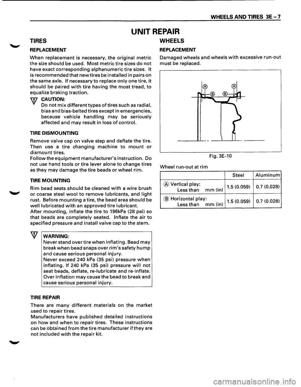
wheels and wheels with excessive run-out
must be replaced.
Fig. 3E-10
Wheel
run-out at rim
Steel Aluminum
@ Vertical play: 1.5 (0.059) 0.7
(0.028) Less than mm(in)
@ Horizontal play: 1.5 (0.059) 0.7
(0.028) Less than mm(in)
Page 309 of 1928
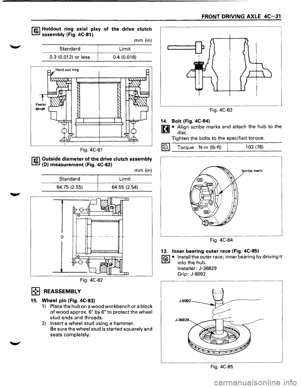
r.r.il Holdout ring axial play of the drive clutch
1..!!:.1 assembly (Fig. 4C-81 ).
mm (in)
Standard Limit
----~----------------0.3 (0.012) or less 0.4 (0.016)
Fig. 4C-81
r.r.il Outside diameter of the drive clutch assembly
1..!!:.1 (D) measurement (Fig. 4C-82)
Standard
64.75 (2.55)
Fig. 4C-82
l•! .. l REASSEMBLY
15. Wheel pin (Fig. 4C-83)
mm (in)
Limit
64.55 (2.54)
1) Place the hub on a wood workbench or a block
of wood approx. 6" by 6" to protect the wheel
stud ends and threads.
2) Insert a wheel stud using a hammer.
Be sure the wheel stud is started squarely and
seats completely.
FRONT DRIVING AXLE 4C-31
...____[)
Fig. 4C-83
14.
Bolt (Fig. 4C-84)
0 • A.lign scribe marks and attach the hub to the
1!!:!1 diSC.
Tighten the bolts to the specified torque.
~~~ Torque N·m (lb·ft) I 103 (76)
Scribe mark
Fig. 4C-84
13.
Inner bearing outer race (Fig. 4C-85)
1'?.:\1 • Install the outer race; inner bearing by driving it
l..::5::il into the hub.
Installer: J-36829
Grip:
J-8092
Fig. 4C-85
Page 518 of 1928
6A-2 GENERAL ENGINE MECHANICAL
NOTE:
•
During disassembly, be sure that the valve train
components are kept
together and identified so
that they can be re-installed in their original
locations.
• Before removing the cylinder head from the
engine and before disassembling the valve
mechanism, perform a compression test and note
the results.
1•! .. 1 DISASSEMBLY
(SOHC)
1. Camshaft timing pulley
2. Front plate
3. Camshaft bracket fixing bolts
4. Camshaft, oil seal and camshaft end plug
• Remove them with camshaft bracket.
5. Rockershaft assembly (Exhaust side)
6. Rockershaft assembly (Intake side)
7. Spark plug
\fl CAUTION:
VI • Do not remove the spark plugs when the head
and plugs are hot.
• Clean dirt and debris from spark plug recess
areas.
(DOHC)
1. Camshaft timing pulley
2. Front plate
3. Camshaft bracket fixing bolts
4. Chain tensioner fixing bolts
5. Camshaft, oil seal and camshaft end plug
• Remove them with chain and chain tensioner
6. Swing arm.
7. Hydraulic lash adjusters (HLA)
NOTE:
Immerse HLA in engine oil, taking care nottoturn it
upside down or sideways in order to prevent any
air
from entering into HLA.
8. Spark plug
\flCAUTION:
VI • Do not remove the spark plugs when the head
and plugs are hot.
• Clean dirt and debris from spark plug recess
areas.
f}l CLEAN
• Cylinder head
Carefully remove
all varnish, soot and carbon
to the bare metal. Do not use a motorized wire
brush on any gasket sealing surface.
IL'~'IINSPECTION AND REPAIR
• Cylinder head gasket and mating surfaces for
leaks, corrosion and blow-by. If the gasket has
failed, determine the cause. Insufficient
torque on head bolts
Improper installation
Loose
or warped cylinder head
Missing
dowel pins
- Warped case surface
1. Cylinder head bolts for damaged threads or
stretching and damaged heads caused by
improper use of tools.
\fl CAUTION:
VI Replace used cylinder head bolts.
2. Cylinder head for cracks, especially between valve
seats and in the exhaust ports.
3. Cylinder head deck for corrosion, sand particles in
head and porosity.
\fl CAUTION:
VI Do not attemptto weld the cylinder head. Replace
it.
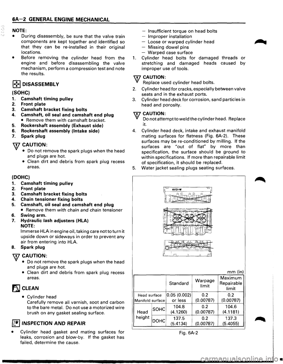
4. Cylinder head deck, intake and exhaust manifold
mating surfaces for flatness (Fig. 6A-2). These
surfaces
may be re-conditioned by milling. If the
surfaces are
"out of flat" by more than
specification, the surface should be ground
to
within specifications. If more than repairable limit
of specification, it should be replaced.
5. Water jacket sealing plugs seating surfaces.
IIVD1-w 8~
~ I 0 I ' 0 0 I 0
mm (in)
Warpage
Maximum
Standard Repairable limit limit
Head surface 0.05 (0.002) 0.2
0.2
Manifold surface or less (0.00787) (0.00787)
SOHC 104.8 0.2
104.6
Head (4.1260) (0.00787) (4.1181)
height
DOHC 137.5 0.2 137.3
(5.4134)
(0.00787) (5.4055)
Fig. 6A-2
•
Page 1564 of 1928
8-374 CHASSIS ELECTRICAL
SEAT HEATER
GENERAL DESCRIPTION
The circuit consists of the starter switch, seat heater switch and the heat unit.
The seat heater is provided in driver's and front passenger seats
(as option). When the seat heater switch is
ON, the seat heater built in the seat back and cushion is switched on to warm the seats.
To prevent the seats
from being overheated, the circuit is fitted with a thermostat.
Ill
Page 1646 of 1928
9J-22 Supplemental Restraint System
AIR BAG TO EXPAND IN THE UNLIKELY EVENT OF
ACCEIDENTAL DEPLOYMENT. FAILURE TO
FOLLOW PROCEDURES MAY RESULT IN
PERSONAL INJURY.
26. Temporarily store the inflator module with the bag
facing up, away from the surface upon which it rests.
27.
Call the Technical Assistance group for further
assistance.
DEPLOYMENT INSIDE VEHICLE(VEHICLE
SCRAPPING PROCEDURE)
Deployment inside vehicle is proper when the vehicle is
to be destroyed or
salvaged for component parts. This
includes, but is not limited to, the following situations.
1. The vehicle has completed its useful life.
2. The vehicle has been damaged beyond repair in a
non-deployment type accident.
3. The vehicle has been stripped or damaged beyond
repair
in a theft.
4. The vehicle will be salvaged for component parts to
be
used on a vehicle with a different Vehicle
Identification Number (VIN) as opposed to being
rebuilt as same VIN. Never use SRS components
from another
vehicle. This is done to ensure SRS
system integrity since only new SRS system
components.
WARNING: FAILURE TO FOLLOW PROPER SRS
INFLATOR MODULE DISPOSAL PROCEDURES
CAN RESULT IN AIR BAG DEPLOYMENT WHICH
MAY CAUSE PERSONAL INJURY. UNDEPLOYED
INFLATOR MODULES MUST NOT BE DISPOSED OF
THROUGH NORMAL REFUSE CHANNELS. THE
UNDEPLOYED INFLATOR MODULE CONTAINS
SUBSTANCES THAT CAL CAUSE SEVERE ILLNESS
OR
PERSONAL INJURY IF THE SEALED
CONTAINER IS DAMAGED DURING DISPOSAL.
DISPOSAL IN ANY MANNER INCONSISTENT WITH
PROPER PROCEDURES MAY BE A VIOLATION OF
FEDERAL, STATE AND/OR LOCAL LAWS.
1. Turn ignition switch to "LOCK," remove key and put
on safety glasses.
2. Remove all loose objects from front seats.
3. Disconnect driver inflator module, yellow 3-way
connector located at the base of the steering column.
4. Cut the driver inflator module yellow 2-way harness
connector from the
vehicle leaving at least 16 cm(six
inches) of wire at the connector.
5. Strip 13 mm(1/2 inch) of insulation from each wire
lead of the connector.
6. Cut two 900 cm(30 feet) deployment wires from
0.8mm2(18 gauge) or thicker
multi-strand wire. These
wires
will be used to fabricate the driver
deployment harness.
7. Strip 13 mm(1/2 inch) of insulation from both ends of
the wires cut
in the previous step.
8. Short the wires by twisting together one end from
each. Deployment wires
shall remain shorted and
not
be connected to a power source until the air bag
is to be
deployed.
WARNING: FAILURE TO
FOLLOW PROCEDURES
IN
THE ORDER LISTED COULD RESULT IN
PERSONAL INJURY. NEVER CONNECT
DEPLOYMENT WIRES TO ANY POWER SOURCE
BEFORE CONNECTING DEPLOYMENT WIRES TO
THE INFLATOR MODULE LEADS. DEPLOYMENT
WIRES SHALL REMAIN SHORTED AND NOT BE
CONNECTED TO A POWER SOURCE UNTIL THE
AIR BAG IS TO BE DEPLOYED. THE INFLATOR
MODULE WILL IMMEDIATELY DEPLOY THE AIR
BAG WHEN A POWER SOURCE IS CONNECTED TO
IT. WEAR SAFETY GLASSES THROUGHOUT THIS
ENTIRE DEPLOYMENT AND DISPOSAL
PROCEDURE.
9. Twist together one connector wire lead to one
deployment wire. The connection should be
mechanically secure.
10. Bend twisted connection made in the previous step
flat and wrap tightly with electrical tape to insulate ~
and secure.
11. Twist together, bend and tape the remaining
connector wire lead to the remaining deployment
wire.
12. Connect the deployment harness to the driver
inflator module, yellow 2-way connector at the base
of the steering
column. Route deployment harness
out the driver side of the
vehicle.
WARNING:
DEPLOYMENT WIRES SHALL REMAIN
SHORTED
AND NOT BE CONNECTED TO A POWER
SOURCE UNTIL THE AIR BAG IS TO BE DEPLOYED.
THE INFLATOR MODULE WILL IMMEDIATELY
DEPLOY THE AIR BAG WHEN A POWER SOURCE IS
CONNECTED TO IT.
CONNECTING THE DEPLOYMENT WIRES TO THE
POWER
SOURCE SHOULD ALWAYS BE THE FINAL
STEP IN
THE INFLATOR MODULE DEPLOYMENT
PROCEDURE. FAILURE TO FOLLOW
PROCEDURES IN THE ORDER LISTED COULD
RESULT IN PERSONAL INJURY.
13. Disconnect passenger inflator module, yellow 2-way
connector located behind 1/P compartment door
assembly.
14. Cut the passenger inflator module harness
connector from the vehicle leaving at least 16 cm(six
inches) of wire at the connector).
Page 1760 of 1928
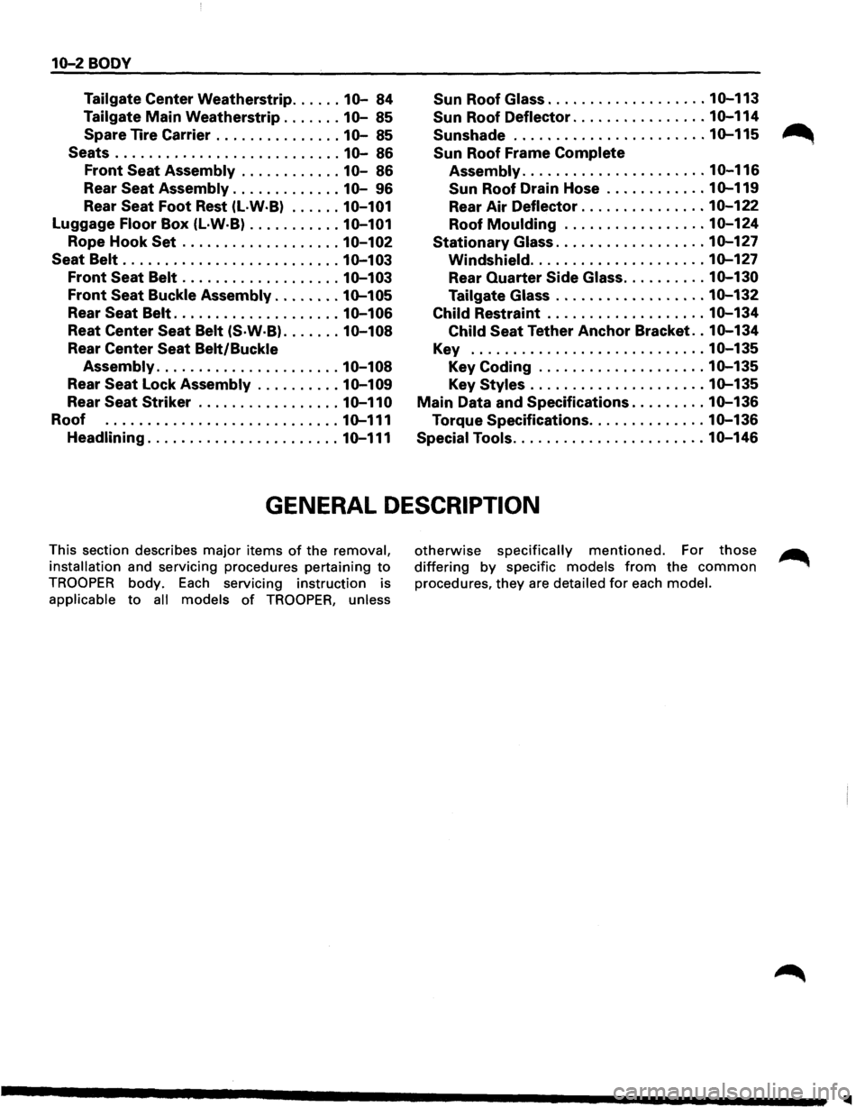
10-2 BODY
Tailgate Center Weatherstrip ...... 10-84 Sun Roof Glass ................... 10-113
Tailgate Main Weatherstrip ....... 10-85
Spare Tire Carrier
............... 10-85
Sun Roof Deflector ................ 10-114
Sunshade ....................... 10-115 ~
Seats ........................... 10-86 Sun Roof Frame Complete
Front Seat Assembly ............ 10-86 Assembly ...................... 10-116
Rear Seat Assembly ............. 10-96 Sun Roof Drain Hose ............ 10-119
Rear Seat Foot Rest (L·W·B) ...... 10-101 Rear Air Deflector ............... 10-122
Luggage Floor Box (L·W·B) ........... 10-101 Roof Moulding ................. 10-124
Rope Hook Set ................... 10-102 Stationary Glass .................. 10-127
Seat
Belt .......................... 10-103 Windshield ..................... 10-127
Front Seat Belt ................... 10-103 Rear Quarter Side Glass .......... 10-130
Front Seat Buckle Assembly ........ 10-105 Tailgate Glass .................. 10-132
Rear Seat Belt .................... 10-106 Child Restraint ................... 10-134
Reat Center Seat Belt (S·W·B) ....... 10-108 Child Seat Tether Anchor Bracket .. 10-134
Rear Center Seat Belt/Buckle Key ............................ 10-135
Assembly ...................... 10-108 Key
Coding .................... 10-135
Rear Seat Lock Assembly .......... 10-109 Key Styles ..................... 10-135
Rear Seat Striker ................. 10-110 Main Data and Specifications ......... 10-136
Roof ............................ 10-111 Torque Specifications .............. 10-136
Headlining ....................... 10-111 Special Tools ....................... 10-146
GENERAL DESCRIPTION
This section describes major items of the removal,
installation
and servicing procedures pertaining to
TROOPER body. Each servicing instruction is
applicable to all models of TROOPER, unless
otherwise specifically mentioned. For those
differing by specific models from the common
procedures, they are detailed for each model.
..
Page 1844 of 1928
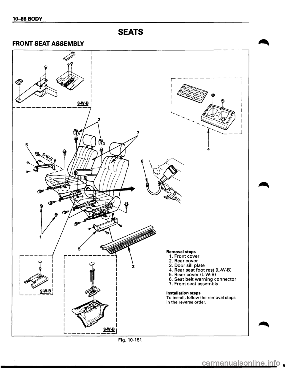
10-86BODY
FRONT SEAT ASSEMBLY
~ : I
I I
1
,-----
1 0
: t
:~
~~,
I S·W·BI L ______ :J
I
I
I
I
I I I
I
I I
I S·W·B
r-----------
1 q
! 1 I ! ..
~~
I
I
I
I
I I
L _______ S·W·!J
SEATS
3
Fig.
10-181
Removal steps
1. Front cover 2.Rearcover 3. Door sill plate 4. Rear seat foot rest (l·W·B) 5. Riser cover (L·W·B) 6. Seat belt warning connector 7. Front seat assembly
Installation steps
To install, follow the removal steps
in the reverse order.
II