jump start ISUZU TROOPER 1995 Workshop Manual
[x] Cancel search | Manufacturer: ISUZU, Model Year: 1995, Model line: TROOPER, Model: ISUZU TROOPER 1995Pages: 1928
Page 416 of 1928
5A4-6 4-WHEEL ANTILOCK BRAKE SYSTEM (ABS)
If only rear wheels are rotated using jacks or
drum tester, the system will diagnose a speed
sensor
malfunction and the "ABS" warning
light will illuminate. But actually no trouble
exists. After inspection stop the engine once
and re-start it,
then make sure that the "ABS"
warning light does not illuminate.
If the battery has been discharged
The engine may stall if the battery has been
completely discharged and the engine is started via
a
jumper cable. This is because the Antilock Brake
System (ABS) requires a
large quantity of
electricity. In this case, wait until the battery is
recharged,
or set the ABS to a non-operative state
by removing the fuse for the ABS (40A). After the
battery has been recharged, stop the engine and
install the ABS fuse. Start the engine again, and
confirm that the ABS warning light does not light.
NOTE ON INTERMITTENTS
As with virtually any electronic system, it is difficult
to identify an intermittent failure. In such a case
duplicating the system malfunction during a test
drive
or a good description of vehicle behavior from
the customer may be helpful in locating a "most
likely" failed component or circuit. The symptom
diagnosis chart may also be useful in isolating the
failure. Most intermittent problems are caused by
faulty electrical connections or wiring. When an
intermittent failure is encountered, check suspect
circuits for:
Suspected harness damage.
• Poor mating of connector halves or terminals
not fully seated in the connector body (backed
out).
Improperly formed or damaged terminals.
TEST DRIVING ABS COMPLAINT
VEHICLES
In case that there has been an abnormality in the
lighting pattern of "ABS" warning light, the fault
can be located in accordance with the "DIAGNOSIS
BY 'ABS' WARNING LIGHT ILLUMINATION
PATTERN". In case of such trouble as can be
detected
by the driver as a vehicle symptom,
however, it is necessary to give a test drive
following the test procedure mentioned below,
thereby reproducing the symptom for trouble
diagnosis on a symptom basis:
1. Start the engine and make sure that the "ABS"
W/L goes OFF. If the W/L remains ON, it
means that the Diagnostic Trouble Code (DTC)
is stored. Therefore, read the code and
locate
the fault.
2. Start the vehicle and accelerate to 30 km/h (19
mph) or more.
3. Slowly brake and stop the vehicle completely.
4. Then restart the vehicle and accelerate to 40
km/h (25 mph) or more.
5. Brake at a time so as to actuate the ABS and ... ~
stop the vehicle.
6. Be cautious of abnormality during the test. If
theW/Lis actuated while driving, read the DTC
and locate the fault.
7. If the abnormality is not reproduced by the
test, make best efforts
to reproduce the
situation reported
by the customer.
8. If the abnormality has been detected, repair in
accordance
with the "SYMPTOM DIAGNOSIS".
NOTE:
Be sure to give a test drive on a wide, even
road
with a small traffic.
If an abnormality is detected, be sure to
suspend the test and start
trouble diagnosis at
once.
II ABS" WARNING LIGHT
When ABS trouble occurs to actuate "ABS"
warning light, the trouble code corresponding to
the trouble is stored in the EBCM. Only ordinary
brake is available with ABS being unactuated. Even
when "ABS" warning light is actuated, if the starter
switch is set
ON after setting it OFF once, the EBCM
checks
up on the entire system and, if there is no
abnormality, judges ABS to work currently and the
warning light is lit normally even though the
trouble code is stored.
NOTE:
Illumination of the "ABS" warning light
indicates that antilock braking is no longer
available. Power assisted braking without
antilock control is still available.
NORMAL OPERATION
II ABS" WARNING LIGHT
When the ignition is first moved from "OFF" to
"RUN", the amber "ABS" warning light will turn
"ON". The "ABS" warning light will turn "ON"
during engine starting and will usually stay "ON"
for approximately three seconds after the ignition
switch is returned to the "ON" position. The
warning light should remain "OFF" at all other
times.
•
Page 457 of 1928
4-WHEEL ANTILOCK BRAKE SYSTEM (ASS) 5A4-47
DIAGNOSTIC TROUBLE CODES (DTCs)
When the warning light in the meter remains ON, the EBCM stores the fault identification and disables the
.........,.. ABS.
1. How to display and erase DTCs:
NOTE:
• If DTCs are not displayed, harness BB 14 may be disconnected. Repair the harness and try DTC
display again.
• DTCs can be displayed also by TECH 1. For further details, see "MODE F2: TROUBLE CODE" in this
section.
(1)
How to start DTC display:
• Confirm
that the vehicle has come to a complete stop (with the wheels standing still) and that the
brake pedal is not depressed. (Unless these two condition are satisfied, DTC display cannot be
started.)
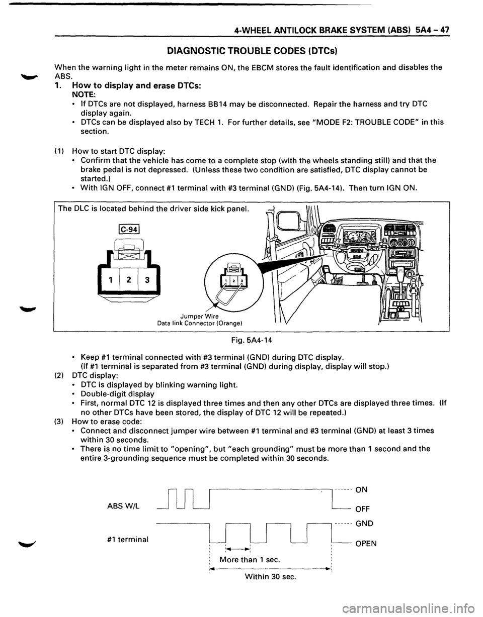
• With IGN OFF, connect #1 terminal with #3 terminal (GND) (Fig. 5A4-14). Then turn IGN ON.
The DLC is located behind the driver side kick panel.
1 2 3
Jumper Wire Data link Connector (Orange}
Fig. 5A4-14
• Keep #1 terminal connected with #3 terminal (GND) during DTC display.
(If
#1 terminal is separated from #3 terminal (GND) during display, display will stop.)
(2) DTC display:
•
DTC is displayed by blinking warning light.
•
Double-digit display
•
First, normal DTC 12 is displayed three times and then any other DTCs are displayed three times. (If
no other DTCs have been stored, the display of DTC 12 will be repeated.)
(3) How to erase code:
• Connect and disconnect jumper wire between #1 terminal and #3 terminal (GND) at least 3 times
within 30 seconds.
• There is no time limit to "opening", but "each grounding" must be more than 1 second and the
entire 3-grounding sequence must be completed within 30 seconds.
ABS W/L
#1 terminal
r---------------, ------ON
More than 1 sec.
OFF
.--------, ------ GND
OPEN
' ,._ _________ ,_:
Within 30 sec.
Page 501 of 1928
ENGINE DIAGNOSIS 6-3
HARD STARTING
1. Starting motor does not turn over
Trouble shooting procedure
Turn on headlights and starter switch.
Condition Possible cause Correction
Headlights go out or dim Battery run down or under charged Recharge or replace battery
considerably
Terminals poorly connected Clean battery posts and
terminals and connect properly
Starting motor coil circuit shorted Overhaul or replace
Starting motor defective
Headlights stay
bright Starting motor circuit open Refer to Section 6D
Starting
motor coil open Replace
2. Ignition trouble -Starting motor turns over but engine does not start
Spark Test
Disconnect a high tension cable from any spark plug. Connect the spark plug tester J-26792 (ST-1 25).
start the engine, and check if a spark is generated in the spark plug tester.
Before starting the engine, make sure
that the spark plug tester is properly grounded. To avoid
electrical shock, do not touch the high tension cable while the engine is running.
Condition Possible cause Correction
Spark jumps across gap
Spark plug defective Clean, adjust spark gap or
replace
Ignition
timing incorrect Refer to Section 6E2
Fuel not reaching fuel injector(s) or Refer to item 3
engine (Trouble
in
fuel system)
Valve
timing incorrect Adjust
Engine
lacks compression Refer to item 4
(Engine
lacks compression)
No sparking takes
place Spark plug wire disconnected or broken Connect properly or replace
Electronic Ignition System with module Replace
Poor connections in engine harness
Correct
Engine Control
Module cable Correct or replace
disconnected or defective
3. Trouble in fuel system
Condition Possible cause Correction
Starting motor turns over and
Fuel tank empty Fill
spark occurs but engine does
not start. Water in fuel system Clean
Fuel filter clogged Replace filter
Fuel pipe clogged Clean or replace
Fuel pump defective
Replace
Fuel
pump circuit open Correct or replace
Evaporative Emission Control System Correct or replace
circuit clogged
Multipart Fuel Injection System faulty Refer to "Electronic Fuel
Injection"
section
Page 646 of 1928
![ISUZU TROOPER 1995 Workshop Manual 6C - 4 ENGINE FUEL
I1!]1NSPECTION
After installation, start engine and check for fuel leak
age.
IN-TANK FUEL FILTER
The filter is located on the lower end of fuel pickup
tube in the fuel tank](/img/61/57183/w960_57183-645.png "ISUZU TROOPER 1995 Workshop Manual 6C - 4 ENGINE FUEL
I1!]1NSPECTION
After installation, start engine and check for fuel leak
age.
IN-TANK FUEL FILTER
The filter is located on the lower end of fuel pickup
tube in the fuel tank")
6C - 4 ENGINE FUEL
I1!]1NSPECTION
After installation, start engine and check for fuel leak
age.
IN-TANK FUEL FILTER
The filter is located on the lower end of fuel pickup
tube in the fuel tank. It prevents dirt from entering the
fuel pipe and also stops water unless the filter is
completely submerged in the water. It is a self-cleaning
type, not requiring scheduled maintenance. Excess
water and sediment in the tank restricts fuel supply to
the engine, resulting in engine stop. In such a case, the
tank
must be cleaned throughly.
FUEL PUMP FLOW TEST
If reduction of fuel supply is suspected, perform
checking as follows.
Preparation:
• Make sure that there is fuel in the tank.
• With the engine running, check the fuel feed
pipe and hose
from fuel tank to injector for
evidence of leakage.
Retighten, if pipe or hose connection is loose.
Also,
check pipes and hoses for squashing or
clogging.
1. Receive the hose from fuel feed pipe with a clean
container, and check for fuel pump flow rate.
2. Connect the pump relay terminals with a jumper
wire as shown and start the fuel pump to measure
delivery. (Fig. 6C-4)
W CAUTION:
Never generate sparks when connecting a jumper
wire.
Fig. 6C-4
Delivery Delivery
15 seconds 0.38
liters minimum
If the measure value is out of standard, conduct the
pressure test.
Pressure test
For the pressure test to the fuel system, see Section 6E
"Fuel Control System".
II
Page 655 of 1928
ENGINE ELECTRICAL 601-1
SECTION 60
ENGINE ELECTRICAL
CONTENTS
Battery . . ..... . ...... . ... . .... . .... ..... .... . .... .. .... . .... . . ... . . . .... . . .. . . .... . ... . ... . .... . . .. ... . .... . . ... . ... . . .. . Section 601
Cranking System
........... ... . ... . .... . .... . . .... . .... .
. ... . . .... . .... . .... . . ... ...
.. .... . . ..... . .... . ......... ... Section 602
Charging System ..... .... . . .............. .... . .... . . .. .. . . ... . . ... . . ... . . ... . . ........ .... . . ..... .. .... . ... . .... . .. Section 603
Ignition System (V6 3.2L) .. .... ...... ...... .. .. .. .... ...... .... .. .... .... .... ...... ...... ...... .......... .... Section 6D4A
SECTION 601
BATTERY
CONTENTS
General Description ............................... 6D1-1
Diagnosis .............................................. 6D1-1
On-Vehicle Service ................................ 6D1-3
Battery Charging ................................ 6D1-3
Jump Starting .................................... 6D1-3
Removal and Installation of The Battery . . 6D1-4
Main Data and Specifications . . . . . . . . . . . . . . . . . . 6D1-4
GENERAL DESCRIPTION
There are six battery fluid caps at the top of the
battery. These are covered by a paper
label.
The battery is completely sealed except for the six
small vent holes at the side. These vent holes per
mit the escape of small amounts of gas generated
by the battery.
This type
of battery has the following advantages
over
conventional batteries:
1. There is no need to add water during the entire
service
life of the battery.
2. The battery protects itself against overcharging.
The battery
will refuse to accept an excessive
charge. (A
conventional battery will accept an excessive
charge,
resulting in gassing and loss of battery
fluid.)
3. The battery is much less vulnerable to self
discharge than a conventional type battery.
DIAGNOSIS
1. VISUAL INSPECTION
Inspect the battery for obvious physical damage,
such
as a cracked or broken case, which would per
mit electrolyte loss.
Replace
the battery if obvious physical damage is
discovered during inspection.
Check
for any other physical damage and correct it
as necessary. If not, proceed to Step 2.
2. HYDROMETER CHECK
There is a built-in hydrometer (Charge test indica
tor) at the top of the battery. It is designed to be
used during diagnostic procedures. Before
trying to read the hydrometer,
carefully
clean
the upper battery surface.
If your work area is poorly lit, additional light may
be necessary
to read the hydrometer (Fig. 6D1-1).
a. BLUE RING OR DOT VISIBLE -Go to Step
4.
b. BLUE RING OR DOT NOT VISIBLE -Go to
Step 3.
Page 657 of 1928
ENGINE ELECTRICAL 601-3
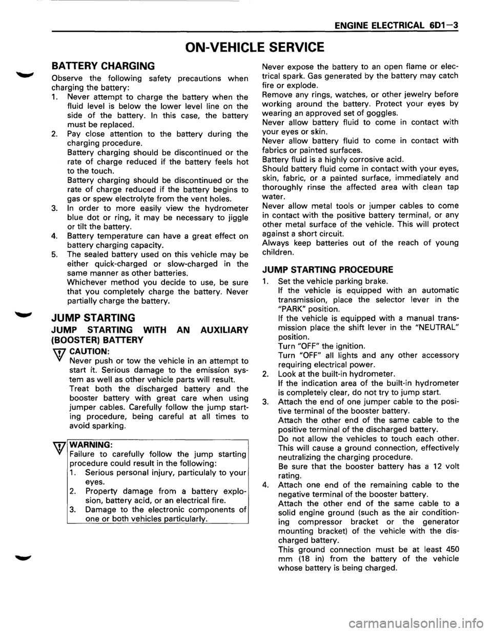
ON-VEHICLE SERVICE
BATTERY CHARGING
Observe the following safety precautions when
charging the battery:
1. Never attempt to charge the battery when the
fluid level is below the lower level line on the
side
of the battery. In this case, the battery
must be replaced.
2. Pay close attention to the battery during the
charging procedure.
Battery charging
should be discontinued or the
rate
of charge reduced if the battery feels hot
to the touch.
Battery charging
should be discontinued or the
rate
of charge reduced if the battery begins to
gas or spew electrolyte from the vent holes.
3. In order to more easily view the hydrometer
blue dot or ring, it may be necessary to jiggle
or tilt the battery.
4. Battery temperature can have a great effect on
battery charging capacity.
5. The sealed battery used on this vehicle may be
either quick-charged or slow-charged in the
same manner
as other batteries.
Whichever method you decide
to use, be sure
that you
completely charge the battery. Never
partially charge the battery.
JUMP STARTING
JUMP STARTING WITH AN AUXILIARY
(BOOSTER)
BATTERY
W CAUTION:
Never push or tow the vehicle in an attempt to
start it.
Serious damage to the emission sys
tem as
well as other vehicle parts will result.
Treat both the discharged battery and the
booster battery
with great care when using
jumper cables. Carefully follow the jump start
ing procedure, being
careful at all times to
avoid sparking.
wwARNING:
Failure to carefully follow the jump starting
procedure
could result in the following:
1. Serious personal injury, particulaly to your
eyes.
2. Property damage from a battery explo
sion, battery acid, or an electrical fire.
3. Damage to the electronic components of
one or both vehicles particularly.
Never expose the battery to an open flame or elec
trical
spark. Gas generated by the battery may catch
fire
or explode.
Remove any rings, watches, or other jewelry before
working around the battery. Protect
your eyes by
wearing
an approved set of goggles.
Never allow battery fluid to come in contact with
your eyes or skin.
Never
allow battery fluid to come in contact with
fabrics or painted surfaces.
Battery
fluid is a highly corrosive acid.
Should battery fluid come in contact with your eyes,
skin, fabric, or a painted surface,
immediately and
thoroughly rinse the affected area with clean tap
water. Never
allow metal tools or jumper cables to come
in contact with the positive battery
terminal, or any
other
metal surface of the vehicle. This will protect
against a short circuit.
Always keep batteries out of the reach of young
children.
JUMP STARTING PROCEDURE
1. Set the vehicle parking brake.
If the vehicle is equipped with an automatic
transmission,
place the selector lever in the
"PARK" position.
If the vehicle is equipped with a manual trans
mission
place the shift lever in the "NEUTRAL"
position.
Turn
"OFF" the ignition.
Turn
"OFF" all lights and any other accessory
requiring
electrical power.
2. Look at the built-in hydrometer.
If the indication area of the built-in hydrometer
is
completely clear, do not try to jump start.
3. Attach the end of one jumper cable to the posi
tive
terminal of the booster battery.
Attach the other end
of the same cable to the
positive
terminal of the discharged battery.
Do not allow the vehicles to touch each other.
This
will cause a ground connection, effectively
neutralizing
the charging procedure.
Be sure that the booster battery has a 12 volt
rating.
4. Attach one end of the remaining cable to the
negative
terminal of the booster battery.
Attach the other end
of the same cable to a
solid engine ground (such as the air condition
ing compressor bracket or the generator
mounting bracket)
of the vehicle with the dis
charged battery.
This ground connection must be at
least 450
mm (18 in) from the battery of the vehicle
whose battery is being charged.
Page 658 of 1928
601-4 ENGINE ELECTRICAL
'IT7 WARNING:
'if Never attach the end of the jumper cable
directly
to the negative terminal of the dead
battery.
5. Start the engine of the vehicle with the good
battery.
Make sure that
all unnecessary electrical acces
sories have been turned
"OFF".
6. Start the engine of the vehicle with the dead
battery.
7. To remove the jumper cables, follow the above
directions in the reverse order.
Be sure to first disconnect the negative cable
from the vehicle with the discharged battery.
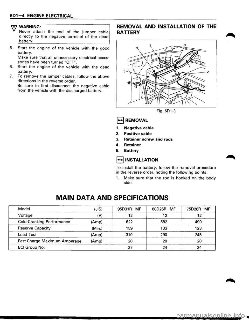
REMOVAL AND INSTALLATION OF THE
BATTERY
5
Fig. 601-3
1+•1 REMOVAL
1. Negative cable
2. Positive cable
3. Retainer screw and rods
4. Retainer
5. Battery
I••IINSTALLATION
To install the battery, follow the removal procedure
in the reverse order, noting the
following points:
1. Make sure that the rod is hooked on the body
side.
MAIN DATA AND SPECIFICATIONS
Model
(JIS) 95D31R-MF 80D26R-MF 75D26R-MF
Voltage (V) 12 12 12
Cold-Cranking Performance (Amp)
622 582 490
Reserve Capacity
(Min.)
159 133
123
Load Test
(Amp)
310 290 245
Fast Charge
Maximum Amperage
(Amp) 20 20 20
BCI Group No. 27 24 24
..
Page 674 of 1928
602 -16 CRANKING SYSTEM
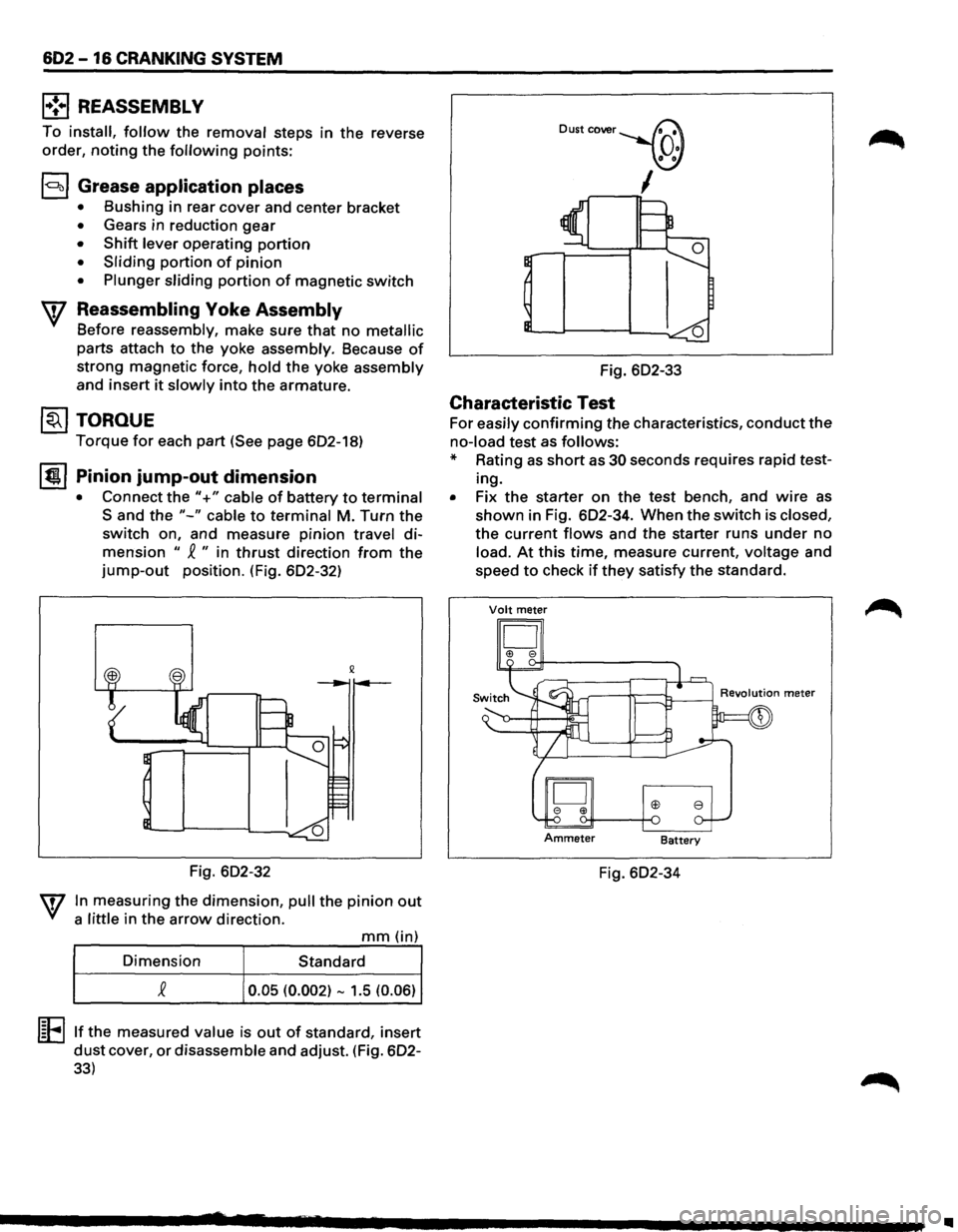
l•!•l REASSEMBL V
To install, follow the removal steps in the reverse
order,
noting the following points:
l<:::~ol Grease application places
• Bushing in rear cover and center bracket
• Gears in reduction gear
• Shift lever operating portion
• Sliding portion of pinion
• Plunger sliding portion of magnetic switch
Reassembling Yoke Assembly
Before reassembly, make sure that no metallic
parts attach to the yoke assembly. Because of
strong magnetic force, hold the yoke assembly
and insert it slowly into the armature.
@J TORQUE
Torque for each part (See page 602-18)
It!!!. I Pinion jump-out dimension
• Connect the"+" cable of battery to terminal
Sand the "-" cable to terminal M. Turn the
switch on, and measure pinion travel di
mension " ~ " in thrust direction from the
jump-out position. (Fig. 602-32)
Fig. 602-32
In measuring the dimension, pull the pinion out
a little in the arrow direction.
mm (in)
Dimension Standard
0.05 (0.002) -1.5 (0.06)
l~Ellf the measured value is out of standard, insert
dust cover, or disassemble and adjust. (Fig. 602-
33)
Dust cover~
_\(J)
,----,1
Fig. 602-33
Characteristic Test
For easily confirming the characteristics, conduct the
no-load test as follows:
* Rating as short as 30 seconds requires rapid test
ing.
• Fix the starter on the test bench, and wire as
shown in Fig. 602-34. When the switch is closed,
the current flows and the starter runs under no
load. At this time, measure current, voltage and
speed
to check if they satisfy the standard.
Volt meter
D I!> e
Fig. 602-34
..
Page 700 of 1928
6E2-4 DRIVEABILITY AND EMISSIONS
BASIC KNOWLEDGE REQUIRED
Before using this section of the Service Manual,
there are some areas that you should be familiar
with. Without this basic knowledge, you will have
trouble using the diagnostic procedures
contained in this section.
BASIC ELECTRIC CIRCUITS
You should understand the basic theory of
electricity, and know the meaning of voltage,
amps, and ohms. You should understand what
happens in a circuit with an open or a shorted
wire. You
should be able to read and understand a
wiring diagram. A shortto ground is referred to as
a ground to distinguish it from a short between
wires.
USE OF CIRCUIT TESTING TOOLS
You should know how to use a test light, how to
connect and use a tachometer, and
how to use
jumper wires to by-pass components to test
circuits. Care
should be taken to not deform the
terminal when testing.
USE OF DIGITAL VOLT-OHM METER
(DVOM)
You should be familiar with the Digital Volt-Ohm
Meter, particularly special tool J-39200 or
equivalent. You should be able to measure
voltage, resistance, and current and know how to
use the meter correctly.
The
Digital Volt-Ohm Meter is covered in the
"Special Tools" portion of this section.
DIAGNOSTIC INFORMATION
The diagnostic "Trouble Tree" charts and func
tional checks in this manual are designed to locate
a faulty circuit or component through logic based
on the process
of elimination. The charts are
prepared
with the requirement that the vehicle
functioned correctly at the time of assembly and
that there are no multiple failures.
The Engine Control Module (ECM) performs a
continual self-diagnosis on certain control
functions. This diagnostic capability is
complemented by the diagnostic procedures
contained in this
manual. The ECM's language for
communicating the source of a malfunction is a
system
of Diagnostic Trouble Codes (DTCs). The
DTC(s) are
two or three digit numbers that can
range from12 to
51. When a malfunction is
detected by the ECM, a DTC is set and the
Malfunction Indicator Lamp is illuminated.
"CHECK ENGINE" MALFUNCTION
INDICATOR
LAMP (MIL)
This light is on the instrument panel and has two
functions:
• It is used to tell the driver that a problem has
occurred, and that the
vehicle should be
taken
for service as soon as reasonably
possible.
• It
is used by the technician to read out
'Trouble Codes" to help diagnose system
problems.
As a bulb and system check, the light will come
"ON" with the key "ON" and the engine not
running. When the engine is started, the light will
turn off. If the light remains on, the self-diagnostic
system has detected a
problem. If the problem
goes away, the light will go out in most cases after
10 seconds, but a Trouble Code will remain stored
in the
ECM.
When the light remains "ON" while the engine is
running,
or when a malfunction is suspected due
to a
driveability or emissions problem, a on-board
diagnostic system check
must be performed. The
procedures
for these checks are given in Section
"A". These checks will expose malfunctions
which may
not be detected if other diagnostics
are performed
prematurely.
INTERMITTENT "CHECK ENGINE"
MALFUNCTION INDICATOR
LAMP (MIL)
In the case of an "intermittent" problem, the
"Check Engine"
malfunction indicator lamp will
light
for ten (1 0) seconds and then will go out.
However, the corresponding
trouble code will be
stored in the
memory of the ECM until the battery
positive
voltage to the ECM has been removed.
When unexpected DTC(s) appear during the
DTC
code reading process, one can assume that these
DTC(s) were set by an intermittent malfunction
and could be helpful in diagnosing the system.
An intermittent
DTC may or may not re-set. If it is
an intermittent failure, a DTC Chart is not used.
Consult the "Diagnostic Aids" on the intermittent
trouble code. Section "B" also covers the topic of
"intermittents". A physical inspection of the
applicable sub-system most often will resolve the
problem.
II
Page 709 of 1928
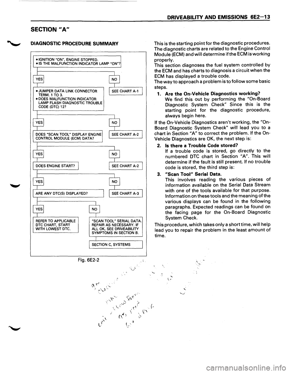
SECTION II A"
DIAGNOSTIC PROCEDURE SUMMARY
•IGNITION "ON", ENGINE STOPPED. •IS THE MALFUNCTION INDICATOR LAMP "ON"?
•
JUMPER DATA LINK CONNECTOR TERM. 1 TO 3. • DOES MALFUNCTION INDICATOR LAMP FLASH DIAGNOSTIC TROUBLE CODE (DTC) 12?
REFER TO APPLICABLE DTC CHART, START WITH LOWEST DTC.
"SCAN TOOL" SERIAL DATA. REPAIR AS NECESSARY. IF ALL OK, SEE DRIVEABILITY SYMPTOMS IN SECTION B.
Fig. 6E2-2
r
DRIVEABILITY AND EMISSIONS 6E2-13
This is the starting point for the diagnostic procedures.
The diagnostic charts are
related to the Engine Control
Module
(ECM) and will determine if the ECM is working
properly.
This section diagnoses the fuel system controlled by
the
ECM and has charts to diagnosis a circuit when the
ECM has displayed a trouble code.
The
way to approach a problem is to follow some basic
steps.
1.
Are the On-Vehicle Diagnostics working?
We find this out by performing the "On-Board
Diagnostic System Check" Since this is the
starting point
for the diagnostic procedure,
always
begin here.
If the On-Vehicle Diagnostics aren't working, the "On
Board Diagnostic System Check" will lead you to a
chart in Section
"A" to correct the problem. If the On
Vehicle
Diagnostics are OK, the next step is:
2.
Is there a Trouble Code stored?
If a trouble code is stored, go directly to the
numbered
DTC chart in Section "A". This will
determine if the fault is still present. If no trouble
code is stored, the third step is:
3. "Scan Tool" Serial Data.
This
involves reading the various pieces of
information available on the Serial Data Stream
with one of the tools available for that purpose.
Information on these tools and the meaning of the
various
displays can be found in the following
paragraphs. Expected readings can be found on
the facing page
for the On-Board Diagnostic
System Check.
This procedure, which takes
only a short time, will help
lead
you to repair the problem in the least amount of
time.