warning lights ISUZU TROOPER 1995 User Guide
[x] Cancel search | Manufacturer: ISUZU, Model Year: 1995, Model line: TROOPER, Model: ISUZU TROOPER 1995Pages: 1928
Page 1478 of 1928
8-288 CHASSIS ELECTRICAL
METER AND WARNING/INDICATOR LIGHT
GENERAL DESCRIPTION
The circuit consists of the starter switch, meter assembly, vehicle speed sensor, clutch switch, transmission
switch, lighting switch,
turn signal switch, thermo unit, oil pressure unit, Engine Control Module, fuel tank unit,
4WD
SW, oil pressure switch, parking brake switch, brake fluid switch, seat belt switch and illumination
controller.
The meter ASM contains the speedometer, tachometer, voltmeter, engine coolant temperature gauge, oil
pressure gauge, fuel gauge and warning/indicator lights.
The meter warning/indicator lights and
their bulb sockets are a unit, they are installed from the back of the
speedometer assembly.
Page 1485 of 1928
CHASSIS ELECTRICAL 8-295
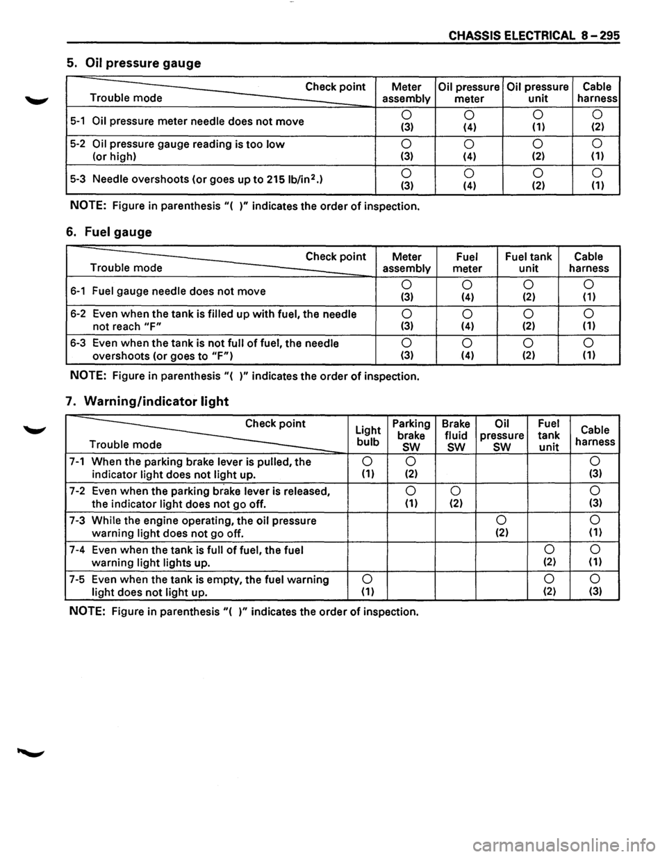
5. Oil pressure gauge
Check point Meter Oil pressure Oil pressure Cable
Trouble mode
assembly meter unit harness
5-1 Oil pressure meter needle does not move 0
0 0
0 (3) (4) (1) (2)
5-2 Oil pressure
gauge reading is too low 0
0 0
0
(or
high) (3) (4) (2) (1)
5-3 Needle overshoots
(or goes up to 2151b/in2.) 0
0 0 0 (3) (4) (2)
(1)
NOTE: Figure
in parenthesis "( )" indicates the order of inspection.
6. Fuel gauge
Check point Meter Fuel Fuel tank Cable
Trouble mode assembly
meter unit harness
6-1 Fuel gauge needle does not move 0
0 0 0 (3) (4) (2) (1)
6-2 Even when the tank is filled up with fuel, the needle 0
0 0
0
not reach "F" (3) (4) (2)
(1)
6-3
Even when the tank is not full of fuel, the needle 0
0 0
0
overshoots (or goes to "F") (3) (4) (2) (1)
NOTE: Figure
in parenthesis "( )" indicates the order of inspection.
7. Warning/indicator light
~
Light Parking
Brake Oil Fuel Cable brake fluid pressure tank bulb sw sw sw unit harness
e
7-1 When the parking brake lever is pulled, the 0 0 0
indicator light does not light up. (1) (2) (3)
7-2 Even
when the parking brake lever is released, 0 0 0
the indicator light does not go off. (1) (2) (3)
7-3 While the engine operating,
the oil pressure 0 0
warning light does not go
off. (2)
(1)
7-4 Even
when the tank is full of fuel, the fuel 0 0
warning light lights
up. (2) (1)
7-5 Even
when the tank is empty, the fuel warning 0 0
0
light does not light up. (1) (2)
(3)
NOTE: Figure in parenthesis "( )" indicates the order of inspection.
Page 1503 of 1928
CHASSIS ELECTRICAL 8-313
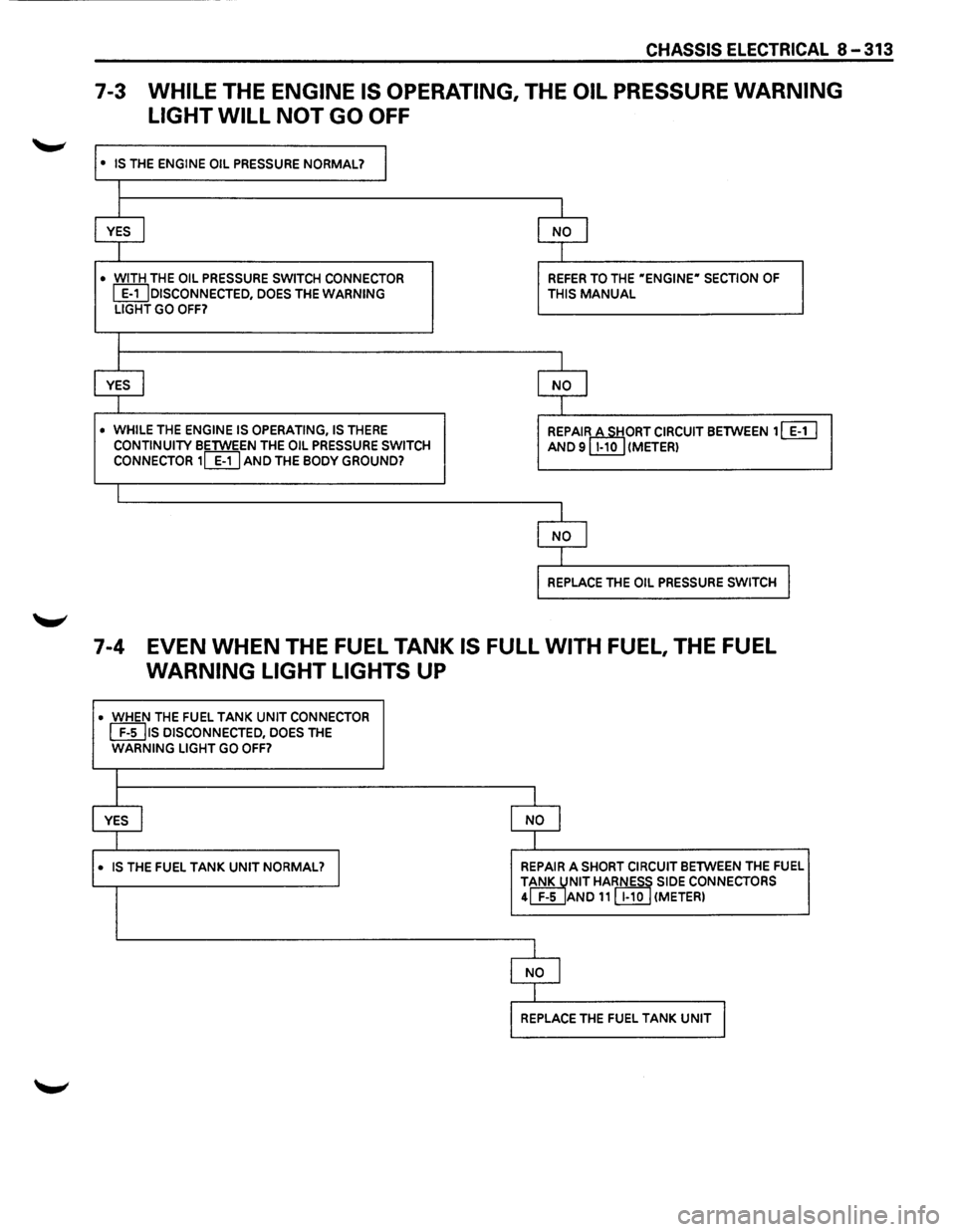
7-3 WHILE THE ENGINE IS OPERATING, THE OIL PRESSURE WARNING
LIGHT WILL
NOT GO OFF
• IS THE ENGINE OIL PRESSURE NORMAL? I
I
I I
YES I NO I
I I
• WITH THE OIL PRESSURE SWITCH CONNECTOR REFER TO THE "ENGINE" SECTION OF
~DISCONNECTED, DOES THE WARNING THIS MANUAL LIGHT GO OFF?
I
I I
YES I NO I
I I
• WHILE THE ENGINE IS OPERATING, IS THERE REPAIRctTIORT CIRCUIT BETWEEN 1 [ill CONTINUITY BETWEEN THE OIL PRESSURE SWITCH AND 9 1-10 (METER) CONNECTOR 1~ AND THE BODY GROUND?
I
I
NO I
I
REPLACE THE OIL PRESSURE SWITCH I
7-4 EVEN WHEN THE FUEL TANK IS FULL WITH FUEL, THE FUEL
WARNING LIGHT LIGHTS UP
• WHEN THE FUEL TANK UNIT CONNECTOR
[EIJ1s DISCONNECTED, DOES THE WARNING LIGHT GO OFF?
l
YES I NO I
I
• IS THE FUEL TANK UNIT NORMAL? I REPAIR A SHORT CIRCUIT BETWEEN THE FUEL
TiNK JNIT HARNESS SIDE CONNECTORS 4 F-5 AND 11 [I!QJ (METER)
1
NO I
I
REPLACE THE FUEL TANK UNIT I
Page 1506 of 1928
8-316 CHASSIS ELECTRICAL
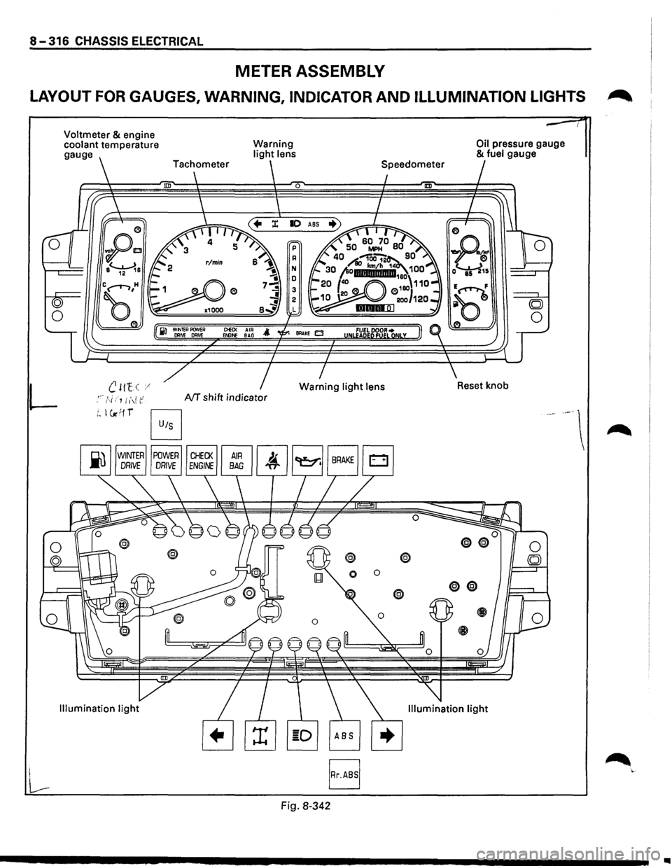
METER ASSEMBLY
LAYOUT FOR GAUGES, WARNING, INDICATOR AND ILLUMINATION LIGHTS .~
L
Voltmeter & engine
coolant temperature
gauge
B
Warning light lens
0
ClEO< AIR Et.llf>E BAG
NT shift indicator
Fig. 8-342
@ @
0 0
Oil pressure gauge & fuel gauge
..
Page 1521 of 1928
![ISUZU TROOPER 1995 User Guide OIL PRESSURE UNIT
(1!] INSPECTION
Measure the resistance value ofthe oil pressure unit
with the circuit tester. (Fig. 8-377)
Replace the
unit when the result of inspection is found
abnorm](/img/61/57183/w960_57183-1520.png "ISUZU TROOPER 1995 User Guide OIL PRESSURE UNIT
(1!] INSPECTION
Measure the resistance value ofthe oil pressure unit
with the circuit tester. (Fig. 8-377)
Replace the
unit when the result of inspection is found
abnorm")
OIL PRESSURE UNIT
(1!] INSPECTION
Measure the resistance value ofthe oil pressure unit
with the circuit tester. (Fig. 8-377)
Replace the
unit when the result of inspection is found
abnormal.
Pressure
(kPa)
Resistance value (Q)
Fig. 8-377
OIL PRESSURE SWITCH
(1!] INSPECTION
98 981
81 30
I~~ Check the continuity between the switch termi
nal and the body ground with the engine at idle.
(Fig. 8-378)
Replace the switch when the result
of inspection
is
found abnormal.
Fig. 8-378
CHASSIS ELECTRICAL 8-331
(1!] CIRCUIT INSPECTION (FIG. 8-379)
Fig. 8-379
1. Start the engine.
2. When disconnecting the oil pressure switch con
nector then connecting the harness side connec
tor to the ground, check to see if the oil pressure
warning light lights up.
When the
light will not light up, check the circuit
between the meter and the oil pressure switch,
and repair
an open circuit if necessary.
FUEL TANK UNIT
The tank unit varies the internal resistance according
to the float position (fluid level) to operate the fuel
meter needle.
It is also designed
to warn the driver of low fuel level
by illuminating the fuel warning light. (Fig. 8-380)
Fig. 8-380