warning lights ISUZU TROOPER 1995 Workshop Manual
[x] Cancel search | Manufacturer: ISUZU, Model Year: 1995, Model line: TROOPER, Model: ISUZU TROOPER 1995Pages: 1928
Page 657 of 1928
ENGINE ELECTRICAL 601-3
ON-VEHICLE SERVICE
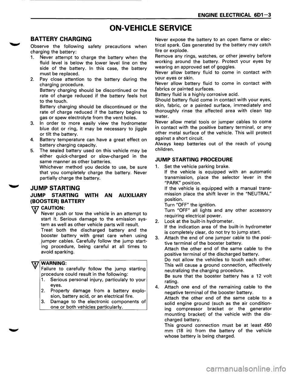
BATTERY CHARGING
Observe the following safety precautions when
charging the battery:
1. Never attempt to charge the battery when the
fluid level is below the lower level line on the
side
of the battery. In this case, the battery
must be replaced.
2. Pay close attention to the battery during the
charging procedure.
Battery charging
should be discontinued or the
rate
of charge reduced if the battery feels hot
to the touch.
Battery charging
should be discontinued or the
rate
of charge reduced if the battery begins to
gas or spew electrolyte from the vent holes.
3. In order to more easily view the hydrometer
blue dot or ring, it may be necessary to jiggle
or tilt the battery.
4. Battery temperature can have a great effect on
battery charging capacity.
5. The sealed battery used on this vehicle may be
either quick-charged or slow-charged in the
same manner
as other batteries.
Whichever method you decide
to use, be sure
that you
completely charge the battery. Never
partially charge the battery.
JUMP STARTING
JUMP STARTING WITH AN AUXILIARY
(BOOSTER)
BATTERY
W CAUTION:
Never push or tow the vehicle in an attempt to
start it.
Serious damage to the emission sys
tem as
well as other vehicle parts will result.
Treat both the discharged battery and the
booster battery
with great care when using
jumper cables. Carefully follow the jump start
ing procedure, being
careful at all times to
avoid sparking.
wwARNING:
Failure to carefully follow the jump starting
procedure
could result in the following:
1. Serious personal injury, particulaly to your
eyes.
2. Property damage from a battery explo
sion, battery acid, or an electrical fire.
3. Damage to the electronic components of
one or both vehicles particularly.
Never expose the battery to an open flame or elec
trical
spark. Gas generated by the battery may catch
fire
or explode.
Remove any rings, watches, or other jewelry before
working around the battery. Protect
your eyes by
wearing
an approved set of goggles.
Never allow battery fluid to come in contact with
your eyes or skin.
Never
allow battery fluid to come in contact with
fabrics or painted surfaces.
Battery
fluid is a highly corrosive acid.
Should battery fluid come in contact with your eyes,
skin, fabric, or a painted surface,
immediately and
thoroughly rinse the affected area with clean tap
water. Never
allow metal tools or jumper cables to come
in contact with the positive battery
terminal, or any
other
metal surface of the vehicle. This will protect
against a short circuit.
Always keep batteries out of the reach of young
children.
JUMP STARTING PROCEDURE
1. Set the vehicle parking brake.
If the vehicle is equipped with an automatic
transmission,
place the selector lever in the
"PARK" position.
If the vehicle is equipped with a manual trans
mission
place the shift lever in the "NEUTRAL"
position.
Turn
"OFF" the ignition.
Turn
"OFF" all lights and any other accessory
requiring
electrical power.
2. Look at the built-in hydrometer.
If the indication area of the built-in hydrometer
is
completely clear, do not try to jump start.
3. Attach the end of one jumper cable to the posi
tive
terminal of the booster battery.
Attach the other end
of the same cable to the
positive
terminal of the discharged battery.
Do not allow the vehicles to touch each other.
This
will cause a ground connection, effectively
neutralizing
the charging procedure.
Be sure that the booster battery has a 12 volt
rating.
4. Attach one end of the remaining cable to the
negative
terminal of the booster battery.
Attach the other end
of the same cable to a
solid engine ground (such as the air condition
ing compressor bracket or the generator
mounting bracket)
of the vehicle with the dis
charged battery.
This ground connection must be at
least 450
mm (18 in) from the battery of the vehicle
whose battery is being charged.
Page 883 of 1928

AUTOMATIC TRANSMISSION (4L30-E) 7 A-11
FUNCTIONS OF INPUT /OUTPUT COMPONENTS
Components Function
Speed sensor
Senses rotation
of output shaft and feeds the data to Transmission
(fixed
to transmission (T/M)) Control Module (TCM)
Throttle Senses the extent of throttle valve opening and the speed of the throttle
position sensor (TPS) valve lever motion to open the valve and feeds the data to TCM (fed to
(fixed to engine)
Engine Control Module (ECM) also)
I
Brake Switch (SW) Senses whether the driver has pressed the brake pedal or not and feeds
N (fixed
to brake pedal) the
information to TCM
p Kick-down SW (fixed to Senses whether the driver has pushed the accelerator pedal fully or not
u accelerator pedal) and feeds the information to TCM
T Mode
SW (fixed to T/M) Senses the select lever position and feeds the information to TCM
s Power drive SW Senses whether the driver has selected the power mode and feeds the
I (fixed to front console) information to TCM
G T/M
oil temp. sensor
Senses the T/M oil temperature and feeds the data to TCM
N Engine
coolant Senses the engine cooling water temperature and feeds the data to TCM
A temperature
SW (feeds the signal from ECM)
L
Engine speed
signal Feeds the signals monitoring engine speed to TCM from Ignition Control
Module
(fed to ECM also)
Air conditioning Senses whether the air conditioner has been switched on or not and
information feeds the information
to TCM
On-board diagnostic
input By monitoring the Ground (GND), the location of failure is shown on the
T/M
monitor lamp ("CHECK TRANS") by flashing the diagnostic trouble
code
Winter switch
Senses whether the driver has selected the winter mode, and feeds the
(fixed
to front console) information to TCM
Cruise
controller Downshift takes place when Overdrive OFF signal is received from auto
(Overdrive
OFF signal) cruise control unit
Shift
solenoid Selects shift point and gear position suited to the vehicle running con-s 1-2/3-4, 2-3
dition on the basis of TCM output 0 Band apply solenoid
Controls oil flow suited to the vehicle running condition on the basis of L
E TCM output
0 N
Torque
Converter Controls clutch engagement/disengagement suited to the vehicle
u 0 Clutch solenoid running condition on the basis of TCM output
T I Force motor Adjusts the oil pump delivery pressure to line pressure suited to the p D
(Pressure regulator vehicle running condition on the basis of TCM output u valve) T
Power drive mode lamp
Informs the driver whether the vehicle is in power mode or not
s Winter drive mode lamp Informs the driver whether the vehicle is in winter mode or not
I T/M monitor lamp Informs the driver of failure in the system. It also displays the self diagnosis
G
("CHECK TRANS") code.
N Data Link Connector
(DLC) When connected with TECH 1 or tester, can communicate the data for A
L function
check, etc. (fed to ECM also). When TECH 1 is not connected, can
communicate the
signal for torque management with ECM.
Self-diagnosis connector
When short-circuited with the bipolar connector, the T/M monitor lamp
displays
a failure by code.
ATF warning
lamp Lights when ATF oil temperature rises.
ABS signal When the select lever is at "Reverse" or "L" range, sends a signal to the
ABS controller as one of the ABS control conditions.
Page 1231 of 1928
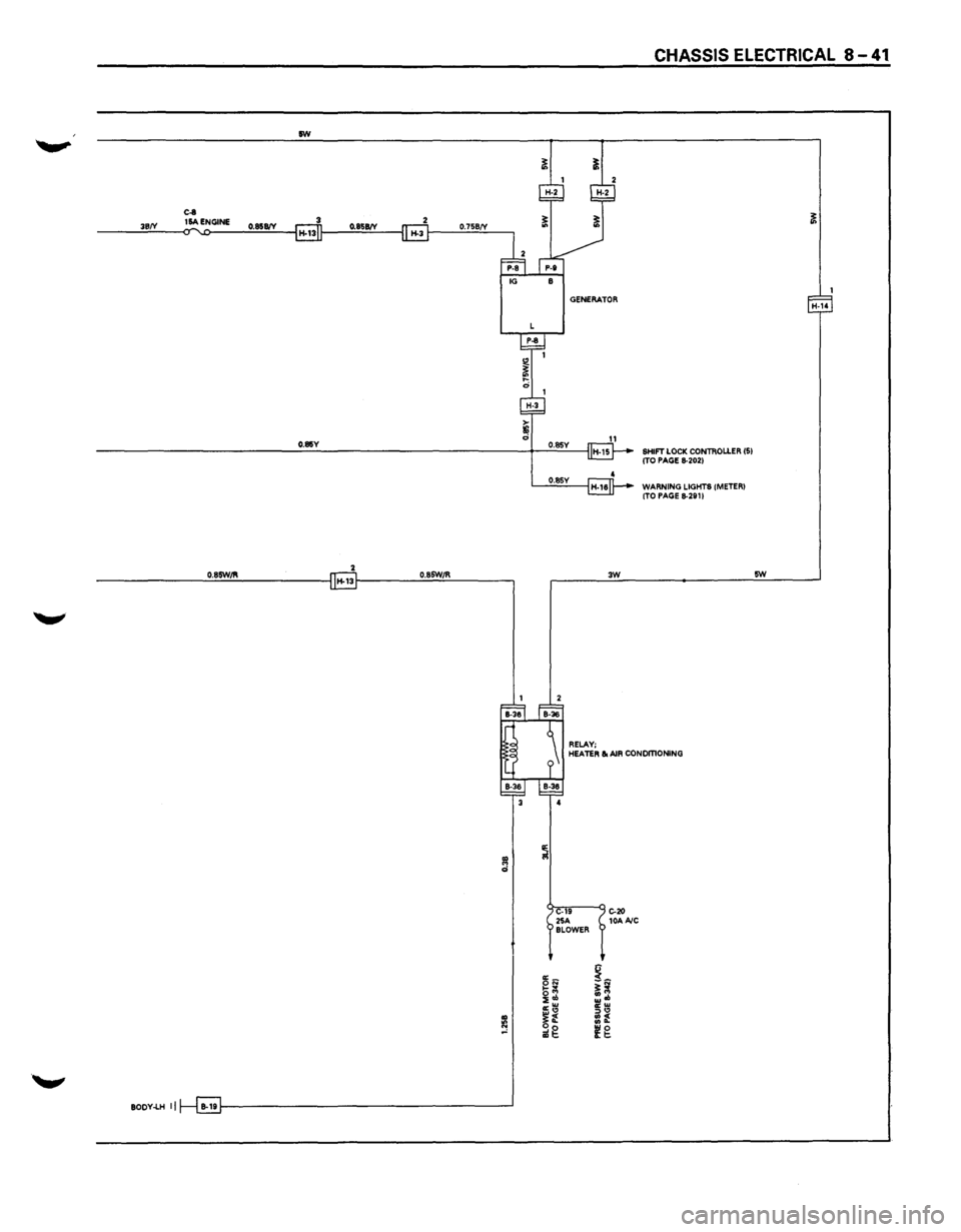
rw
0.85Y
----------------~o~.s~rw~~~-------------l ~13r---------~o-~s~rw~~~--------~
.,
., d
., le '"'
BOOY-LH II
GENERATOR
0.85Y
0.85Y
3W
RELAY;
CHASSIS ELECTRICAL 8-41
SHIFT LOCK CONTROLLER (5) (TO PAGE 8-2021
WARNING LIGHTS (METER) (TO PAGE 8-291 I
5W
HEATER & AIR CONOmONING
~
C-19 C-20 25A 10AAIC SLOWER
~N !~ b(ll ~ol ;~ cr:!l :::><0 ~t :f ~g (g
Page 1296 of 1928
8 - 1 06 CHASSIS ELECTRICAL
TURN SIGNAL LIGHT, HAZARD WARNING LIGHT,
CORNERING LIGHT,
BACKUP LIGHT AND HORN
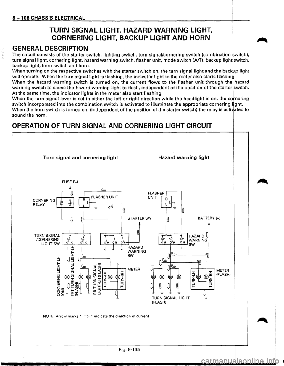
GENERAL DESCRIPTION
The circuit consists of the starter switch, lighting switch, turn signal/cornering switch (combination witch),
turn signal light, cornering light, hazard warning switch, flasher unit, mode switch (A/T), backup light switch,
backup light, horn switch and horn.
When
turning on the respective switches with the starter switch on, the turn signal light and the back p light
will operate. When the turn signal light is flashing, the indicator light in the meter also starts flash in .
When the hazard
warning switch is turned on, the current flows to the flasher unit through the hazard
warning switch to cause the hazard warning light to flash, independent of the position of the starter switch.
At the same time, the indicator lights in the meter also start flashing.
When the
turn signal lever is set in either the left or right direction while the headlight is on, the co nering
switch incorporated
into the combination switch is activated to illuminate the appropriate cornering I ght.
When the horn switch is turned on, (independent
of the position of the starter switch) the relay is acti ated to
sound the horn.
OPERATION OF TURN SIGNAL AND CORNERING LIGHT CIRCUIT
Turn signal and cornering light
CORNERING RELAY
TURN
SIGNAL
/CORNERING FUSE
F-4
~+---------.
Ll G
HT SW L......f-'-=-~--l
STARTER SW
HAZARD
WARNING
sw
NOTE: Arrow marks " ~ " indicate the direction of current
Fig. 8-135
Hazard warning light
D
BATTERY(+)
HAZARD~ WARNING L.f-~'-'----f--' sw
lB
TURN SIGNAL LIGHT
(FLASH)
:z: _J 2: a: :::J 1-
li}
:z: a: 2: a: :::J 1-
~
METER (FLASH)
•
Page 1301 of 1928
CHASSIS ELECTRICAL 8 -111
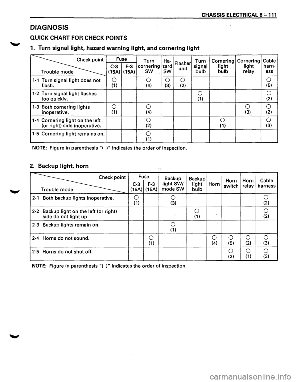
DIAGNOSIS
QUICK CHART FOR CHECK POINTS
1. Turn signal light, hazard warning light, and cornering light
~·
Fuse
Turn Ha-Turn Cornering Cornering Cable Flasher C-3 F-3 cornering
zard
unit signal light light harn-
e (15A)
(15A)
sw
sw bulb bulb relay ess
1-1 Turn signal light does not 0
0 0 0 0
flash. (1) (4) (3) (2) (5)
1-2 Turn
signal light flashes 0 0
too quickly. (1) (2)
1-3 Both
cornering lights 0
0 0
0
inoperative. (1)
(4) (3) (2)
1-4 Cornering light on the left 0 0 0
(or
right) side inoperative. (2) (1) (3)
1-5 Cornering light remains on. 0 (1)
NOTE: Figure in parenthesis"{ )"indicates the order of inspection.
2. Backup light, horn
~·
Fuse
Backup Backup
Horn Horn Cable C-3 F-3 light SW/ light Horn switch relay
harness
e {15A) {15A) modeSW bulb
2-1 Both
backup lights inoperative. 0 0 0 (1) {3) {2)
2-2 Backup light on
the left (or right) 0 0
side do not light up {1) (2)
2-3 Backup lights remain on. b {1)
2-4 Horns do not sound. 0 0
0
0 0 {1) (4) {5) {2) (3)
2-5 Horns do not shut off. 0 0 0 {2) (1) (3)
NOTE: Figure
in parenthesis "{ )" indicates the order of inspection.
Page 1318 of 1928
8-128 CHASSIS ELECTRICAL
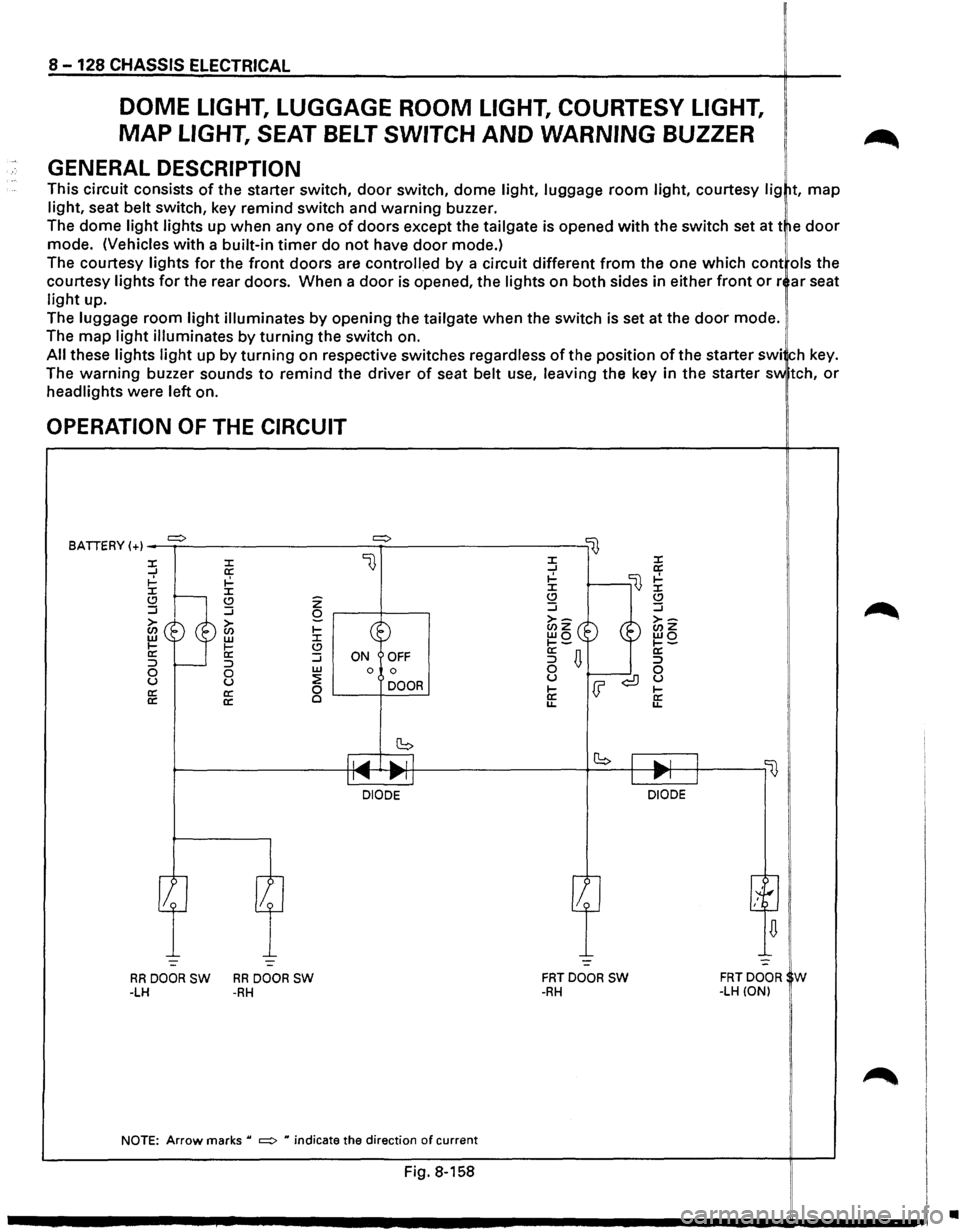
DOME LIGHT, LUGGAGE ROOM LIGHT, COURTESY LIGHT,
MAP LIGHT, SEAT BELT SWITCH AND WARNING BUZZER
GENERAL DESCRIPTION
This circuit consists of the starter switch, door switch, dome light, luggage room light, courtesy lig t, map
light, seat belt switch, key remind switch and warning buzzer.
The dome
light lights up when any one of doors except the tailgate is opened with the switch set at t e door
mode. (Vehicles with a built-in timer do not have door mode.) !
The courtesy lights for the front doors are controlled by a circuit different from the one which cont ols the
courtesy
lights for the rear doors. When a door is opened, the lights on both sides in either front or r ar seat
light up.
The
luggage room light illuminates by opening the tailgate when the switch is set at the door mode.
The
map light illuminates by turning the switch on.
All these lights light up by turning on respective switches regardless of the position of the starter swi ch key.
The
warning buzzer sounds to remind the driver of seat belt use, leaving the key in the starter sv.. tch, or
headlights were left on.
OPERATION OF THE CIRCUIT
BATIERY (+) _....,.=>..:.__ _________ =>~---------lij
l} :X: :X: ...J a: ~ ~ :X: :X: Q .....__ (.!) ...J :J
~~ ®~ II: li: :::> r----:::> 0 0 u u a: a:
a: a:
z Q r---t----,
~ Go (.!) :J w ON OFF 0 0
~ DOOR 0 '-----+------'
~----------~~~~~~~~lr-l ____________ ,_b __ +-~~~-'--~'---,~ II...... 111"""11 Ill"""' J
-:..._ -=-
RRDOORSW RRDOORSW -LH -RH
DIODE DIODE
-=
FRTDOOR SW -RH
NOTE: Arrow marks u =:> H indicate the direction of current
Fig. 8-158
FRTDOOR W -LH (ON)
•
Page 1326 of 1928
8 -136 CHASSIS ELECTRICAL
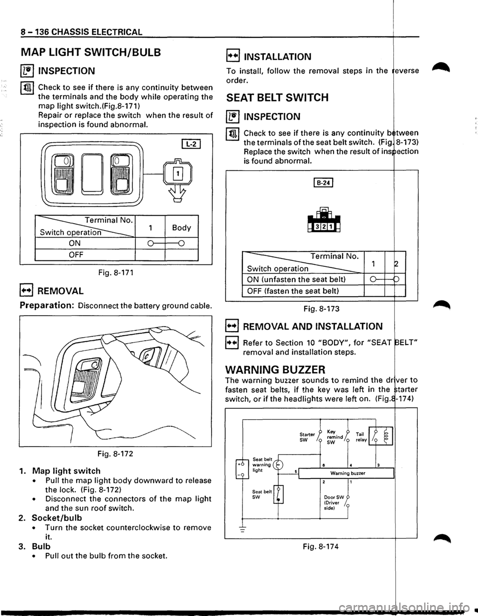
MAP LIGHT SWITCH/BULB
~ INSPECTION
~~~ Check to see if there is any continuity between
the terminals and the body while operating the
map light switch.(Fig.8-171)
Repair
or replace the switch when the result of
inspection is found abnormal.
I" ~ [IT]
ron
0~/~ ~
'
~· 1 Body
n
ON 0 {)
OFF
Fig. 8-171
B REMOVAL
E) INSTALLATION
To install, follow the removal steps in the everse
order.
SEAT BELT SWITCH
~ INSPECTION
I~ l Check to see if there is any continuity b tween
the terminals of the seat belt switch. (Fig 8-173)
Replace the switch when the
result of ins ection
is found abnormal.
Switch operation
ON (unfasten the seat belt)
OFF (fasten the seat belt)
Preparation: Disconnect the battery ground cable. Fig. 8-173
Fig. 8-172
1.
Map light switch
• Pull the map light body downward to release
the
lock. (Fig. 8-172)
• Disconnect the connectors of the map light
and the sun roof switch.
2. Socket/bulb
• Turn the socket counterclockwise to remove
it.
3.
Bulb
• Pull out the bulb from the socket.
B REMOVAL AND INSTALLATION
1++1 Refer to Section 10 "BODY", for "SEAT ELT"
removal and installation steps.
WARNING BUZZER
The warning buzzer sounds to remind the dr ver to
fasten seat belts, if the key was left in the tarter
switch,
or if the headlights were left on. (Fig. -174)
Seat belt warning light
Seat belt
sw
Starter sw
8
Warning buzzer
DoorSW (Driver
side)
Fig. 8-174
..
Page 1327 of 1928
CHASSIS ELECTRICAL 8-137
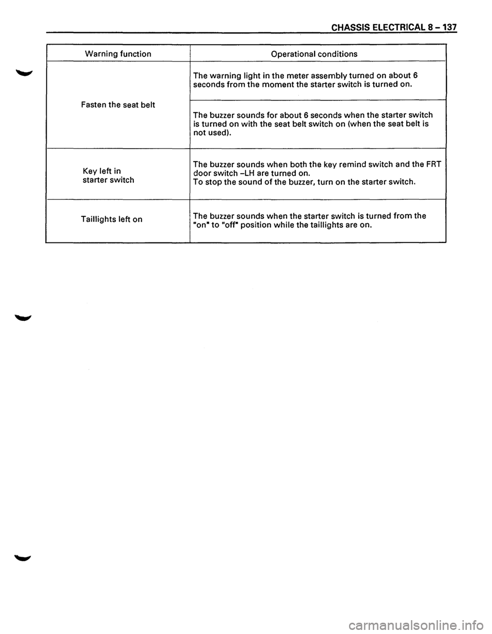
Warning function
Operational conditions
The
warning light in the meter assembly turned on about 6
seconds
from the moment the starter switch is turned on.
Fasten the seat
belt
The buzzer sounds for about 6 seconds when the starter switch
is turned on with the seat belt switch on (when the seat belt is
not used).
Key left in The
buzzer sounds when both the key remind switch and the
FRT
door switch -LH are turned on.
starter switch
To
stop the sound of the buzzer, turn on the starter switch.
Taillights left on The
buzzer sounds when the starter switch is turned
from the
"on• to "off" position while the taillights are on.
Page 1368 of 1928
8 -178 CHASSIS ELECTRICAL
ANTI-LOCK BRAKE SYSTEM (ABS)
GENERAL DESCRIPTION
The circuit consists of the starter switch, stoplight switch (vehicle w/o cruise control), brake switch (vehicle
with cruise control), hydraulic unit, electronic brake control module, wheel speed sensor, G sensor, ABS and
4WD indicator, 4WD switch and data link connector.
When the service brake is applied while in the running mode,
the EBCM (Electronic Brake Control Module)
judges
which wheel is about to lock by using the wheel rotation speed signals sent from the four ABS speed
sensors at the
front and rear wheels. And the brake fluid pressure applied to the four wheels is controlled by
a hydraulic unit to prevent the wheels from locking.
Based on the wheel rotation speed signals
input from the ABS sensor, the EBCM sends out signals to the
solenoid valve in the hydraulic unit
to increase, maintain or decrease the brake fluid pressure. The solenoid
valve uses this signal
to control the fluid pressure which is applied to the calipers of the disk brakes of the
front wheels. (The system also controls at the same time the fluid pressure applied to the rear wheels.)
• EBCM (Electronic brake control module)
The EBCM uses the signals sent from the speed sensor to control the operation of the hydraulic unit.
When any malfunction occurs in the ABS, the
EBCM activates the fail-safe fuction while turning on the
ABS warning light.
• Hydraulic unit
The hydraulic unit consists of the motor, plunger pump, solenoid valve, and fluid pressure control
valves. The exterior
of the unit has a relay box consisting of the motor relay and valve relay. Three
solenoid valves, the
two of which are provided at the front wheels and the one at the rear wheels, control
the fluid pressure
of these wheels.
• Speed sensor
The speed sensor consists of the sensor and the rotor. It sends the EBCM the AC voltage generated by
the rotation of the rotor as the vehicle speed signal. ~
• G-sensor
The G-sensor, installed inside the center console, sends out signals to the EBCM by detecting the
decelerating speed
of the vehicle.
• ABS warning light
The ABS warning light in the instrument panel, lights up when any malfunction occurs in the ABS. It also
lights up
with the starter key at the "ON" position, as a self-check.
Refer
to Section 5A4, "ANTI-LOCK BRAKE SYSTEM" for detail.
II
Page 1460 of 1928
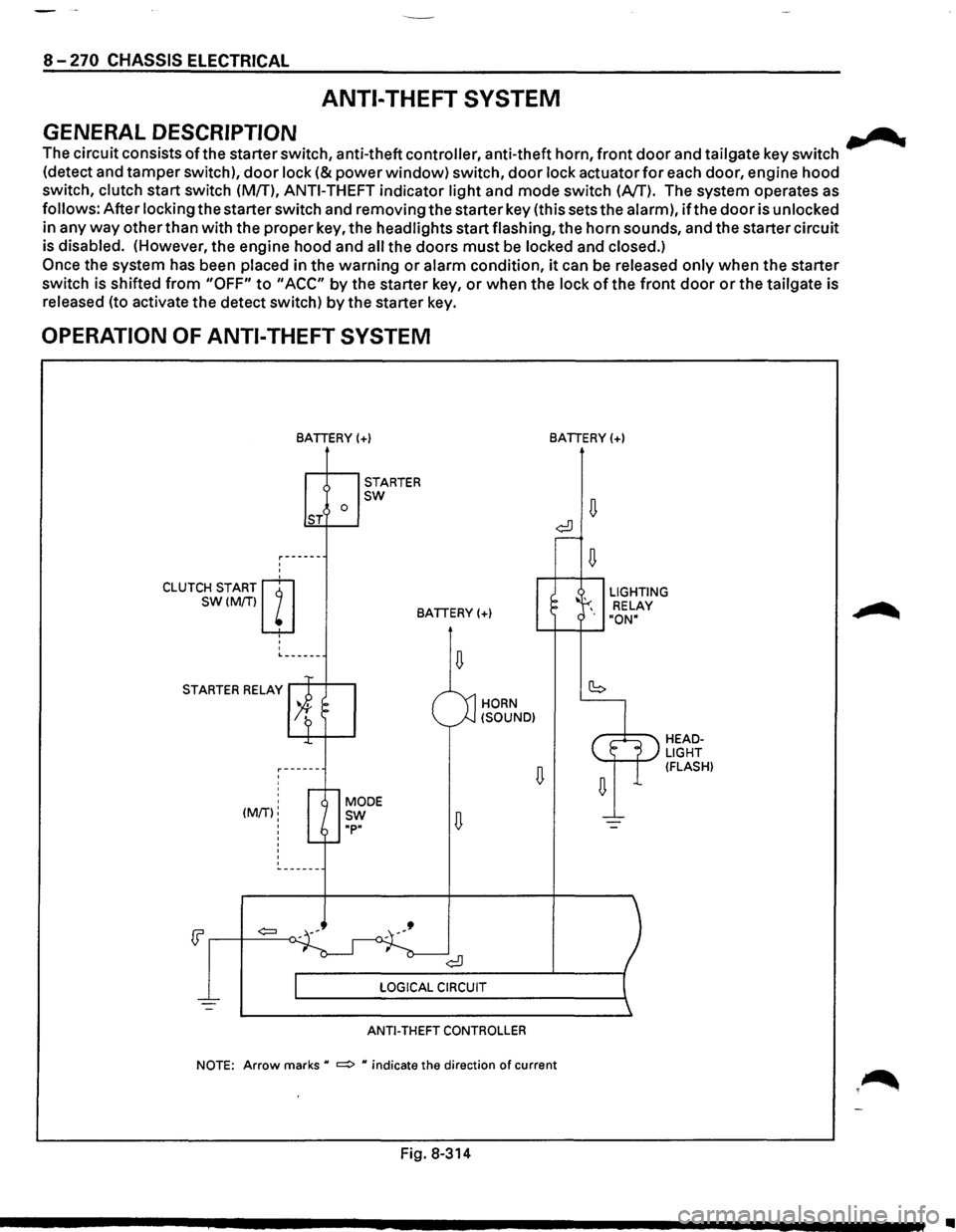
8-270 CHASSIS ELECTRICAL
ANTI-THEFT SYSTEM
GENERAL DESCRIPTION .......
The circuit consists ofthe starter switch, anti-theft controller, anti-theft horn, front door and tailgate key switch
(detect and tamper switch),
door lock (&power window) switch, door lock actuator for each door, engine hood
switch, clutch start switch (MfT),
ANTI-THEFT indicator light and mode switch (AfT). The system operates as
follows: After locking the starter switch and removing the starter key (this sets the alarm),
ifthe door is unlocked
in any
way other than with the proper key, the headlights start flashing, the horn sounds, and the starter circuit
is disabled. (However,
the engine hood and all the doors must be locked and closed.)
Once the system has been placed in the warning or alarm condition, it can be released only when the starter
switch is shifted
from "OFF" to "ACC" by the starter key, or when the lock of the front door or the tailgate is
released (to activate the detect switch)
by the starter key.
OPERATION OF ANTI-THEFT SYSTEM
'
'
CLUTCH START m
SW(M/Tiw
' '
'
BATIERY(+)
0 ST
STARTER sw
BATIERY(+)
L------
STARTER RELAY
' ' (MIT):
'
'
'
HORN
(SOUND)
ANTI-THEFT CONTROLLER
BATIERY(+)
LIGHTING
RELAY
"ON"
HEADLIGHT (FLASH)
NOTE: Arrow marks u ~ u indicate the direction of current
Fig. 8-314
•