wiper fluid ISUZU TROOPER 1995 Workshop Manual
[x] Cancel search | Manufacturer: ISUZU, Model Year: 1995, Model line: TROOPER, Model: ISUZU TROOPER 1995Pages: 1928
Page 1219 of 1928
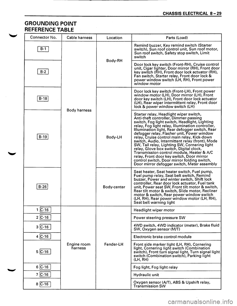
GROUNDING POINT
REFERENCE TABLE
Connector No.
Cable harness
~
~
I B-1a1
Body harness
I B-191
I B-261
1 lc-16 I
2IC-16 I
3IC-16 I
4IC-16 I
Engine room
5IC-16 I
harness
6IC-16 I
7IC-16 I
aiC-16 1
Location
Body-RH
Body-LH
Body-center
Fender-LH
CHASSIS ElECTRICAL 8-29
Parts (Load)
Remind buzzer, Key remind switch (Starter
switch),
Sun roof control unit, Sun roof motor, Sun roof switch, Safety stop switch, Limit
switch
Door lock key switch (Front-RH), Cruise control
unit, Cigar lighter, Door mirror (RH), Front door
key switch (RH), Front door lock actuator (RH),
Fan switch, Starter relay, Front
door lock & power window switch (LH, RH), Front power window motor
Door lock key switch (Front-LH), Front power window motor (LH), Door mirror (LH), Front
door key switch (LH), Front door lock actuator
(LH), Rear wiper intermittent relay, Front door
lock & power window switch (LH)
Starter relay, Headlight
wiper switch,
Anti-theft controller,
Dimmer·passing switch, Fog light switch, Headlight, Lighting
relay, Fog
light relay, Illumination controller,
Illumination light, Rear defogger switch, Rear
defogger relay, Flasher unit,
Power window relay, Cruise control main relay, Kick-down
switch, Audio, Intermittent relay (front), Mode SW, Tail relay, Lighting SW, Cornering light
relay, Glove box switch, Digital clock,
Transmission control module, Heater & A/C
relay, Front
door key switch, Door mirror
control switch, Door mirror folding switch,
Door mirror defogger switch, Meter assembly
Seat heater, Seat heater switch, Fuel pump, Fuel pump relay, Seat belt switch, Remind
buzzer, Power and winter switch, Shift lock
controller, Rear
door lock actuator, Fuel tank
unit, Power seat SW, Front tilt motor & switch,
Rear tilt motor & switch, Slide motor, Recliner
motor & switch, Rear power window switch
(LH, RH), Rear power window motor (LH, RH),
Seat belt warning light
Headlight
wiper motor
Power steering pressure SW
4WD switch, 4WD indicator (meter), Brake fluid
SW, Oxygen sensor (M/T)
Electronic brake control
module
Front side marker light (LH, RH), Cornering
light, Cornering light switch (Combination
switch), Front turn signal light, Turn signal light switch (Combination switch), Parking light (LH, RH)
Fog light, Fog light relay
Hydraulic
unit
Oxygen sensor (AfT), ABS & Upshift relay,
Transmission SW
Page 1395 of 1928
CHASSIS ELECTR1CAL 8-205
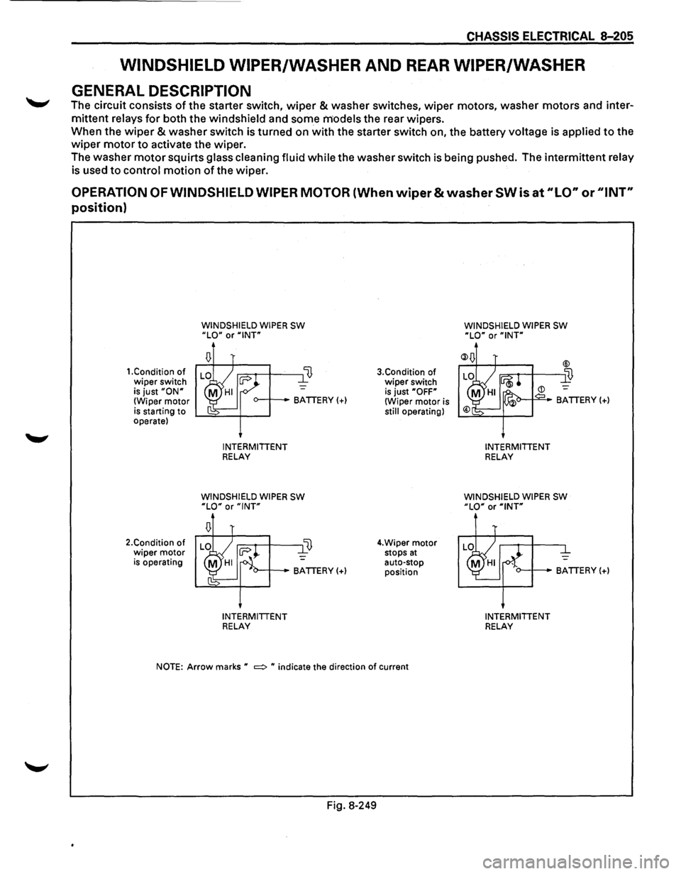
WINDSHIELD WIPER/WASHER AND REAR WIPER/WASHER
GENERAL DESCRIPTION
~ The circuit consists of the starter switch, wiper & washer switches, wiper motors, washer motors and inter
mittent relays for both the windshield and some models the rear wipers.
When the
wiper & washer switch is turned on with the starter switch on, the battery voltage is applied to the
wiper motor to activate the wiper.
The washer
motor squirts glass cleaning fluid while the washer switch is being pushed. The intermittent relay
is used
to control motion of the wiper.
OPERATION OF WINDSHIELD WIPER MOTOR (When wiper & washer SW is at "LO" or ''I NT"
position)
1.Condition of wiper switch is just "ON" (Wiper motor is starting to operate)
2.Condition
of wiper motor is operating
WINDSHIELD WIPER SW "LO" or "INT"
o--+--BATTERY(+)
INTERMITTENT RELAY
WINDSHIELD WIPER SW "LO" or "INT"
INTERMITTENT RELAY
3.Condition of
wiper switch
is just "OFF" (Wiper motor is still operating)
4.Wiper
motor stops at auto-stop position
NOTE: Arrow marks " =:> " indicate the direction of current
Fig. 8-249
WINDSHIELD WIPER SW "LO" or "INT"
INTERMITTENT RELAY
WINDSHIELD WIPER SW "LO" or "INT"
o--+--BATTERY(+)
INTERMITTENT RELAY
Page 1414 of 1928
8-224 CHASSIS ELECTRICAL
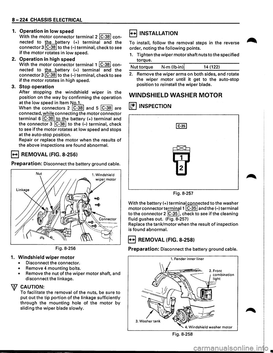
1. Operation in low speed
With the motor connector terminal 2 lC-38l con
nected
to the battery (+) terminal and the
connector3lC-38l
to the(-) terminal, check to see
if the motor rotates in low speed.
2. Operation in high speed
With the motor connector terminal 1 lC-38l con
nected
to the battery (+) terminal and the
connector
3lC-38I to the(-) terminal, check to see
if the motor rotates in high speed.
3.
Stop operation
After stopping the windshield wiper in the
position on the
way by confirming the operation
at the
low speed in Item No.1.
When the connectors 2
lC-381 and 5 lC-381 are
connected,
while connecting the motor connector
terminal 6
IC-381 to the battery (+) terminal and
the connector 3
IC-381 to the H terminal, check
to see if the motor rotates at low speed and stops
at the auto-stop position.
Repair
or replace the motor when the results of
the above inspections are found abnormal.
B REMOVAL (FIG. 8-256)
Preparation: Disconnect the battery ground cable.
Nut 1. Windshield
Fig. 8-256
1.
Windshield wiper motor
• Disconnect the connector.
• Remove 4 mounting bolts.
•
Remove the nut of the wiper motor shaft, and
disconnect the
linkage.
\f CAUTION:
To facilitate the removal of the nuts, be sure to
put out the tip portion of the linkage sufficiently
through the mounting hole of the motor by
sliding the wiper blade slowly.
B INSTALLATION
To install, follow the removal steps in the reverse
order, noting the
following points.
1. Tighten the wiper motor shaft nuts to the specified
torque.
Nut torque N·m (lb·in)j 14 (122)
2. Remove the wiper arms on both sides, and rotate
the
wiper motor until it get to the auto-stop
position
to reinstall the wiper blade.
WINDSHIELD WASHER MOTOR
~ INSPECTION
Fig. 8-257
With the battery(+)
terminal connected to the washer
motor connector terminal1 I C-351 and the(-) terminal
to the connector 2 IC-351, check to see if the cleaning
fluid
gushes out. (Fig. 8-257)
Replace the tank/motor when the result of inspection
is found abnormal.
B REMOVAL (FIG. 8-258)
Preparation: Disconnect the battery ground cable.
1. Fender inner liner
3. Washer tank
Fig. 8-258
•
Page 1420 of 1928
8-230 CHASSIS ELECTRICAL
-~ ~-
20 mm 10.79 in)
Fig. 8-274
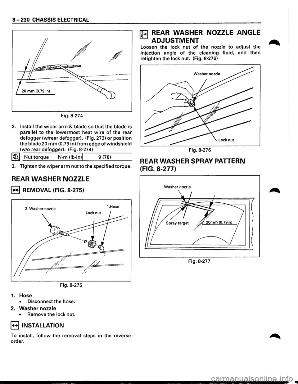
2. Install the wiper arm & blade so that the blade is
parallel to the lowermost heat wire of the rear
defogger (w/rear defogger). (Fig. 273)
or position
the
blade 20 mm (0.79 in) from edge of windshield
(w/o rear defogger). (Fig. 8-274)
~~~ Nut torque N·m Ob·in)l 9 (78)
3. Tighten the wiper arm nut to the specified torque.
REAR WASHER NOZZLE
B REMOVAL (FIG. 8-275)
2. Washer nozzle
Fig. 8-275
1. Hose
• Disconnect the hose.
2. Washer nozzle
• Remove the lock nut.
B INSTALLATION
1.Hose
To install, follow the removal steps in the reverse
order.
ffi3 REAR WASHER NOZZLE ANGLE
ADJUSTMENT
Loosen the lock nut of the nozzle to adjust the
injection angle of the cleaning fluid, and then
retighten the lock nut. (Fig. 8-276)
Washer nozzle
Fig. 8-276
REAR WASHER SPRAY PATTERN
(FIG. 8-277)
Washer nozzle
Fig. 8-277
..
Page 1422 of 1928
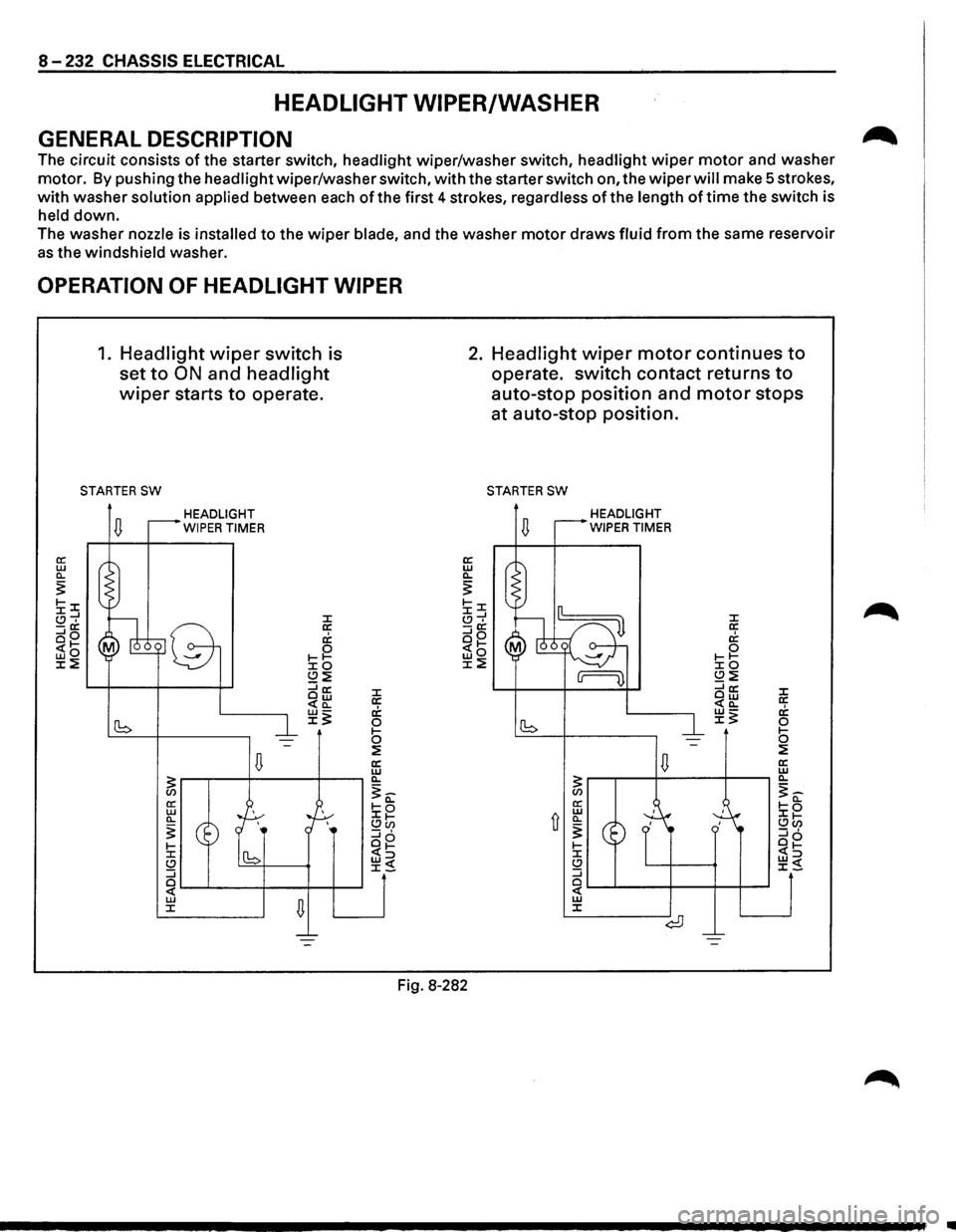
8 -232 CHASSIS ELECTRICAL
HEADLIGHT WIPER/WASHER
GENERAL DESCRIPTION
The circuit consists of the starter switch, headlight wiper/washer switch, headlight wiper motor and washer
motor. By pushing the headlight wiper/washer switch, with the starter switch on, the wiper will make 5 strokes,
with washer solution applied between each of the first 4 strokes, regardless of the length of time the switch is
held down.
The washer nozzle is installed to the wiper blade, and the washer motor draws fluid from the same reservoir
as the windshield washer.
OPERATION OF HEADLIGHT WIPER
1. Headlight wiper switch is
set
to ON and headlight
wiper starts to operate.
STARTER SW
HEADLIGHT
WIPER TIMER
J: a: c1; 0 1-1-J:O (.!)~ ::::ia: Ow <(a_
~~
Fig. 8-282
2. Headlight wiper motor continues to
operate. switch contact returns to
auto-stop position and motor stops
at auto-stop position.
STARTER SW
HEADLIGHT
WIPER TIMER
..