automatic transmission ISUZU TROOPER 1995 Workshop Manual
[x] Cancel search | Manufacturer: ISUZU, Model Year: 1995, Model line: TROOPER, Model: ISUZU TROOPER 1995Pages: 1928
Page 1088 of 1928
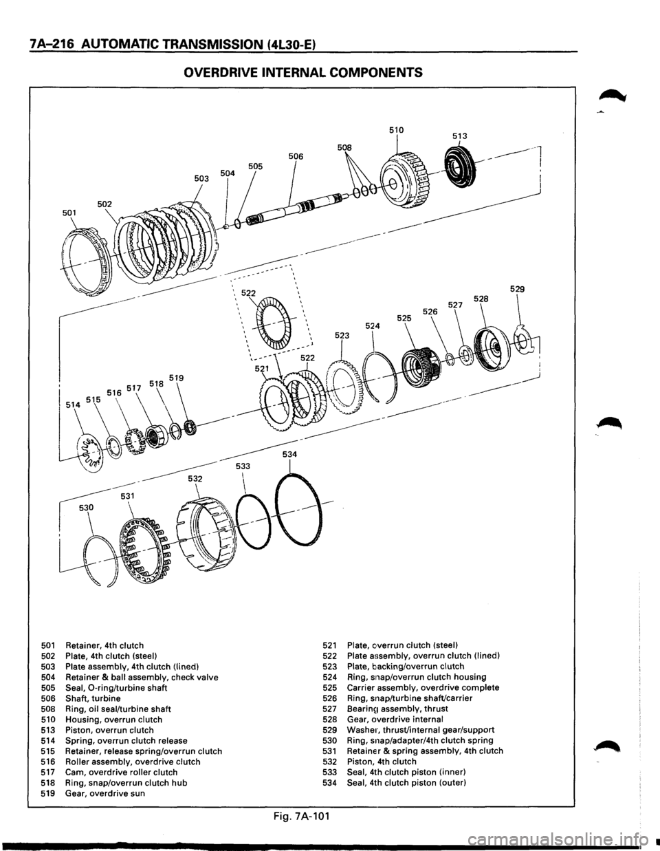
7A-216 AUTOMATIC TRANSMISSION (4L30-E}
OVERDRIVE INTERNAL COMPONENTS
501 Retainer, 4th clutch
502 Plate, 4th clutch (steel) 503
503 Plate assembly,
4th clutch (lined)
504 Retainer & ball assembly, check valve
505 Seal, 0-ring/turbine shaft 506 Shaft, turbine 508 Ring, oil seal/turbine shaft 510 Housing, overrun clutch 513 Piston, overrun clutch 514 Spring, overrun clutch release 515 Retainer, release spring/overrun clutch 516 Roller assembly, overdrive clutch 517 Cam, overdrive roller clutch 518 Ring, snap/overrun clutch hub 519 Gear, overdrive sun
\52\12 \, ' ' ' -' ' '
' ' ' ' ' J ------' -,_-
510
521 Plate, c•verrun clutch (steel) 522 Plate a~;sembly, overrun clutch (lined)
523 Plate, backing/overrun clutch 524 Ring, snap/overrun clutch housing
525 Carrier assembly, overdrive complete 526 Ring, snap/turbine shaft/carrier
527 Bearin~1 assembly, thrust 528 Gear, overdrive internal 529 Washer, thrust/internal gear/support 530 Ring, snap/adapter/4th clutch spring 531 Retainer & spring assembly, 4th clutch 532 Piston, 4th clutch 533 Seal, 4th clutch piston (inner)
534 Seal, 4th clutch piston (outer)
Fig. 7A-101
529
•
Page 1090 of 1928
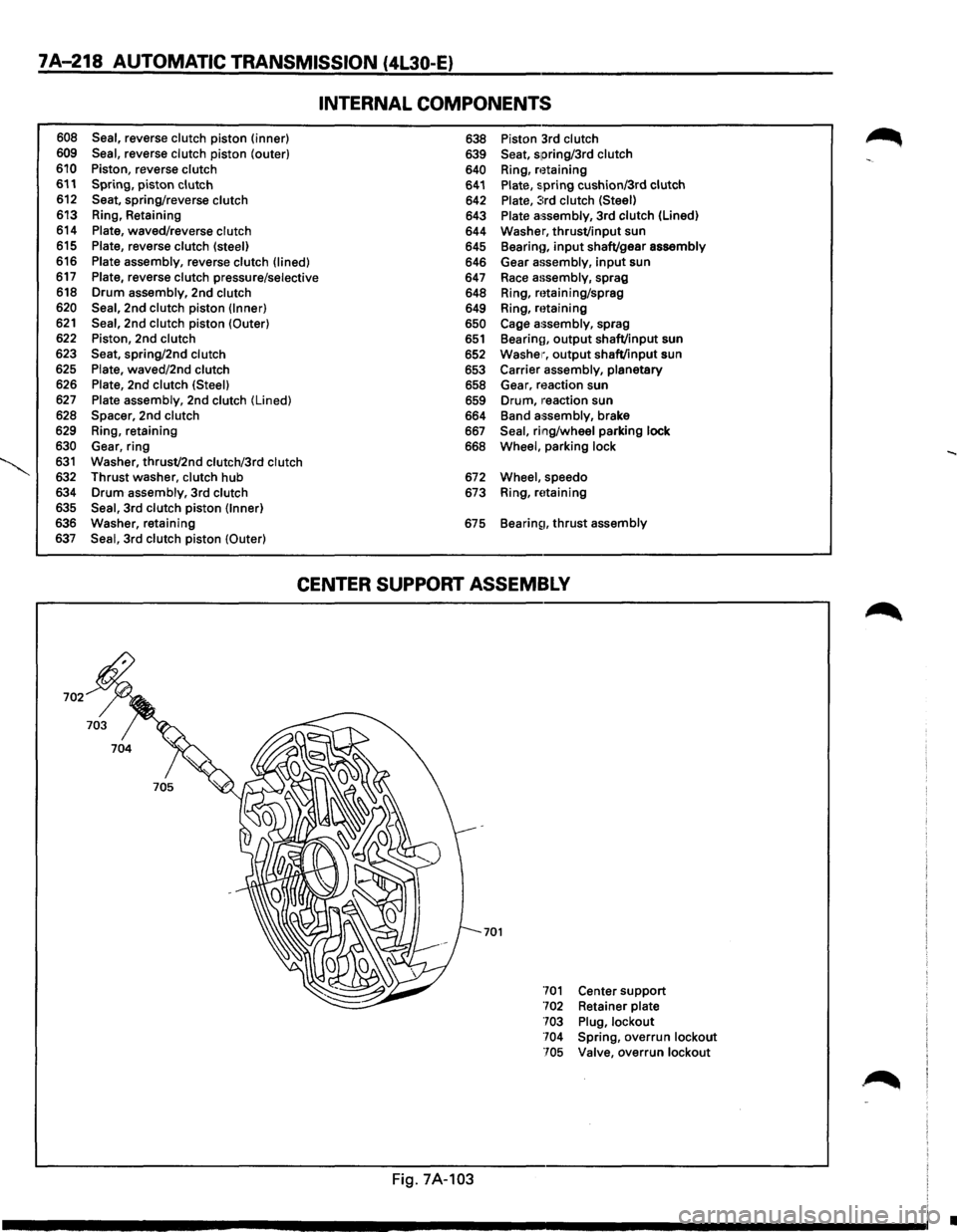
7A-218 AUTOMATIC TRANSMISSION (4L30-E}
608 Seal, reverse clutch piston (inner)
609 Seal, reverse clutch piston (outer)
610 Piston, reverse clutch 611 Spring, piston clutch 612 Seat, spring/reverse clutch 613 Ring, Retaining
614
Plate, waved/reverse clutch 615 Plate, reverse clutch (steel) 616 Plate assembly, reverse clutch (lined)
617 Plate, reverse clutch pressure/selective
618 Drum assembly, 2nd clutch
620 Seal, 2nd clutch piston (Inner) 621 Seal, 2nd clutch piston (Outer) 622 Piston, 2nd clutch
623 Seat, spring/2nd clutch 625 Plate, waved/2nd clutch 626 Plate, 2nd clutch (Steel)
627 Plate assembly, 2nd clutch (Lined)
628 Spacer, 2nd clutch 629 Ring, retaining
630 Gear, ring 631 Washer, thrust/2nd clutch/3rd clutch 632 Thrust washer, clutch hub
634 Drum assembly, 3rd clutch
635 Seal, 3rd clutch piston (Inner) 636 Washer, retaining
637 Seal, 3rd clutch piston (Outer)
INTERNAL COMPONENTS
638 Piston 3rd clutch 639 Seat, spring/3rd clutch
640 Ring, n~taining 641 Plate, spring cushion/3rd clutch 642 Plate, :::rd clutch (Steel) 643 Plate assembly, 3rd clutch (Lined)
644 Washer,
thrust/input sun
645 Bearino, input shaft/gear assembly 646 Gear assembly, input sun
647
Race assembly, sprag
648 Ring, mtaining/sprag
649 Ring,
mtaining 650 Cage a:;sembly, sprag 651 Bearinn, output shaft/input sun
652 Washer, output shaft/input sun
653 Carrier assembly, planetary 658 Gear, reaction sun
659 Drum, 1·eaction sun
664 Band
assembly, brake 667 Seal, ring/wheel parking lock 668 Wheel, parking lock
672 Wheel, speedo
673 Ring, rEttaining
675
Bearin~1. thrust assembly
CENTER SUPPORT ASSEMBLY
701
Fig. 7A-103
701 Center support 702 Retainer plate
703 Plug, lockout
704 Spring,
overrun lockout
705 Valve,
overrun lockout
•
Page 1199 of 1928
CHASSIS ELECTRICAL 8-9
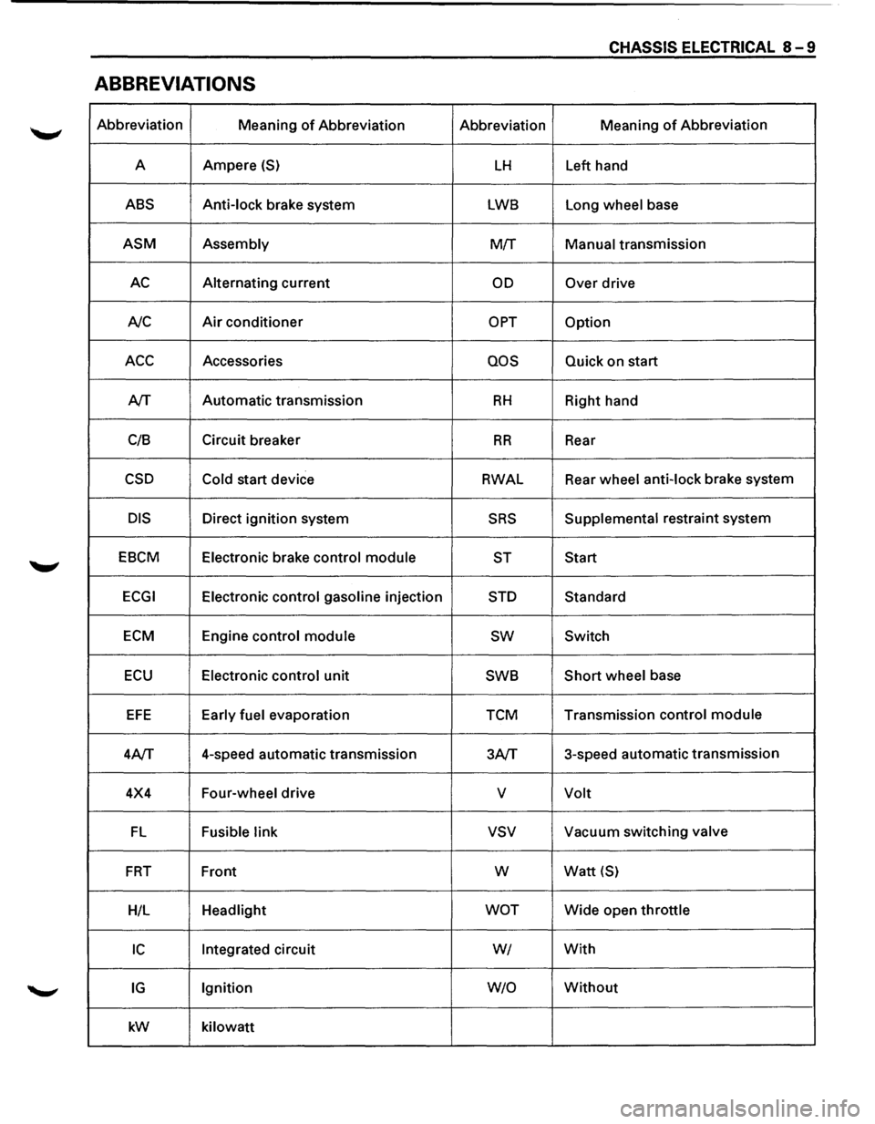
ABBREVIATIONS
Abbreviation
Meaning of Abbreviation Abbreviation Meaning of Abbreviation
A Ampere
(S) LH Left
hand
ABS Anti-lock brake system LWB Long wheel base
ASM Assembly M!f Manual transmission
AC Alternating current OD Over drive
A/C
Air conditioner OPT Option
ACC Accessories QOS Quick on start
A/T Automatic
transmission
RH Right hand
C/8 Circuit
breaker
RR Rear
CSD Cold start device RWAL Rear
wheel anti-lock brake system
DIS Direct ignition system SRS Supplemental restraint system
EBCM Electronic brake control module
ST Start
ECGI Electronic control gasoline injection STD Standard
ECM Engine control module sw Switch
ECU Electronic control unit SWB Short wheel
base
EFE Early fuel evaporation TCM Transmission
control module
4A/T 4-speed
automatic transmission
3A/T 3-speed
automatic transmission
4X4 Four-wheel drive
v Volt
FL Fusible link vsv Vacuum switching valve
FRT Front w Watt {S)
H/L Headlight WOT Wide open throttle
IC Integrated circuit WI With
IG Ignition W/0 Without
kW
kilowatt
Page 1313 of 1928
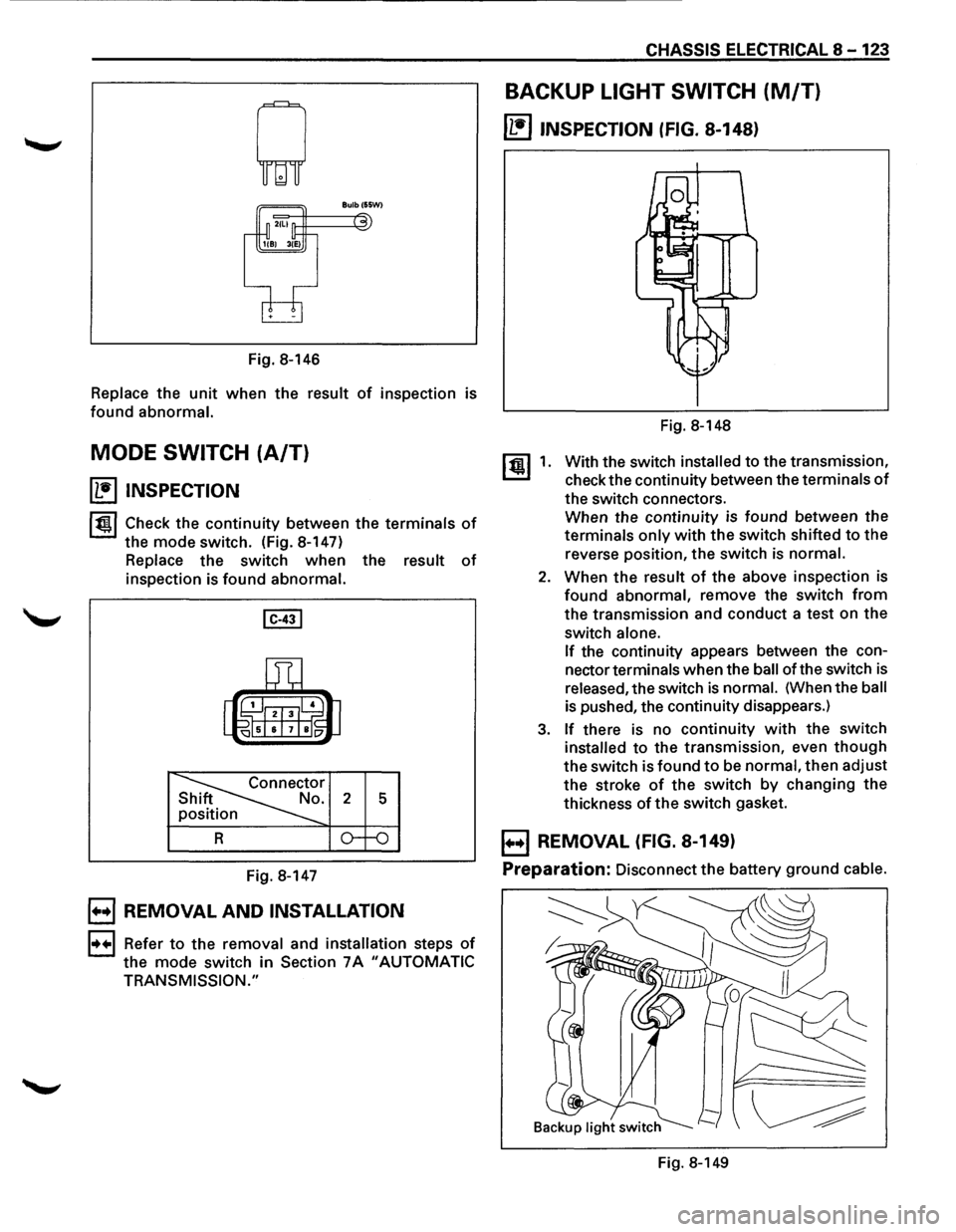
Fig. 8-146
Replace the unit when the result of inspection is
found abnormal.
MODE SWITCH (A/T)
~ INSPECTION
1~1 Check the continuity between the terminals of
the mode switch. (Fig. 8-147)
Replace the switch when the result of
inspection is found abnormal.
Fig. 8-147
B REMOVAL AND INSTALLATION
1••1 Refer to the removal and installation steps of
the mode switch in Section 7A "AUTOMATIC
TRANSMISSION."
CHASSIS ELECTRICAL 8-123
BACKUP LIGHT SWITCH (M/T)
~ INSPECTION (FIG. 8-148}
[!) 1.
Fig. 8-148
With the switch
installed to the transmission,
check the continuity between the
terminals of
the switch connectors.
When the continuity is found between the
terminals only with the switch shifted to the
reverse position, the switch
is normal.
2. When the result of the above inspection is
found abnormal, remove the switch from
the transmission and conduct a test on the
switch
alone.
If
the continuity appears between the con
nector
terminals when the ball of the switch is
released, the switch is normal. (When the ball
is pushed, the continuity disappears.)
3. If there is no continuity with the switch
installed to the transmission, even though
the switch is found to be normal, then adjust
the stroke
of the switch by changing the
thickness
of the switch gasket.
B REMOVAL (FIG. 8-149}
Preparation:
Disconnect the battery ground cable.
Fig. 8-149
Page 1382 of 1928
8-192 CHASSIS ELECTRICAL
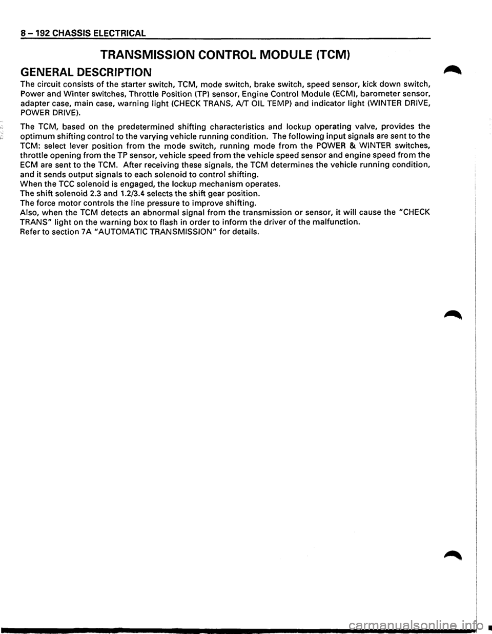
TRANSMISSION CONTROL MODULE (TCM)
GENERAL DESCRIPTION
The circuit consists of the starter switch, TCM, mode switch, brake switch, speed sensor, kick down switch,
Power and
Winter switches, Throttle Position (TP) sensor, Engine Control Module (ECM), barometer sensor,
adapter case, main case,
warning light (CHECK TRANS, NT OIL TEMP) and indicator light (WINTER DRIVE,
POWER DRIVE).
The TCM, based on the predetermined shifting characteristics and lockup operating valve, provides the
optimum shifting control to the varying vehicle running condition. The following input signals are sent to the
TCM: select lever position from the mode switch, running mode from the POWER & WINTER switches,
throttle opening from the TP sensor, vehicle speed from the vehicle speed sensor and engine speed from the
ECM are sent to the TCM. After receiving these signals, the TCM determines the vehicle running condition,
and
it sends output signals to each solenoid to control shifting.
When the
TCC solenoid is engaged, the lockup mechanism operates.
The shift
solenoid 2.3 and 1.2/3.4 selects the shift gear position.
The force
motor controls the line pressure to improve shifting.
Also, when the TCM detects an abnormal signal from the transmission or sensor, it will cause the "CHECK
TRANS"
light on the warning box to flash in order to inform the driver of the malfunction.
Refer to section 7 A "AUTOMATIC TRANSMISSION" for details.
•
Page 1394 of 1928
·;.
8 -204 CHASSIS ELECTRICAL
STARTER SWITCH
Refer to "START AND CHARGING" in this section.
STOPLIGHT
STOPLIGHT SWITCH
BRAKE SWITCH
Refer to "STOPLIGHT AND REAR DEFOGGER" in
,c, this section.
SHIFT LOCK CONTROLLER
Refer to the shift lock controller in Section 7 A
"AUTOMATIC TRANSMISSION."
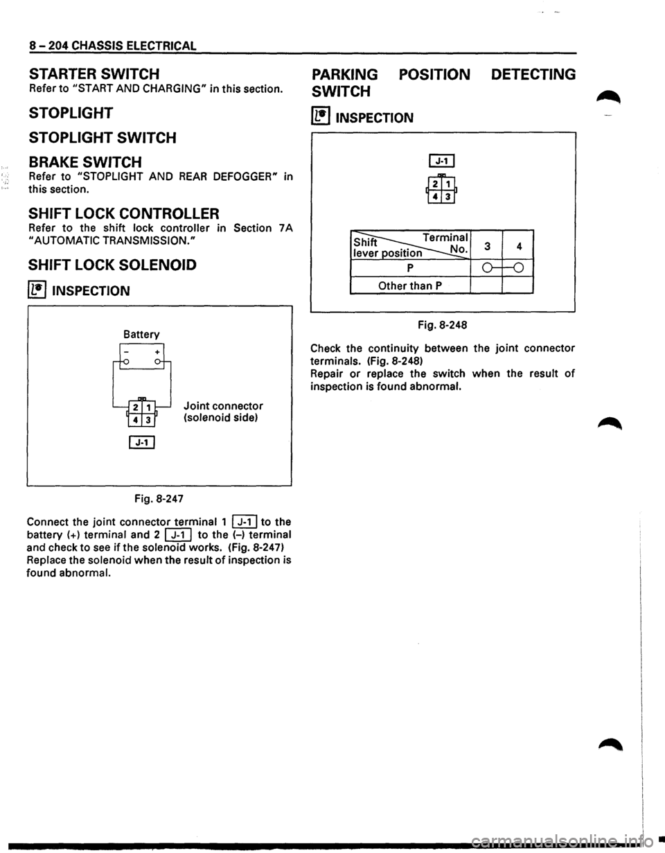
SHIFT LOCK SOLENOID
~ INSPECTION
Fig. 8-247
Joint connector
(solenoid side)
Connect the
joint connector terminal 1 ~to the
battery
(+) terminal and 2 [ill to the (-) terminal
and check to
see if the solenoid works. (Fig. 8-247)
Replace the solenoid when the result
of inspection is
found abnormal.
PARKING POSITION DETECTING
SWITCH
~
(1!]1NSPECTION
l2Ti1
Lill1
Other than P
Fig. 8-248
Check the continuity between the
joint connector
terminals. (Fig. 8-248)
Repair
or replace the switch when the result of
inspection is found abnormal.
I
I I
.............. ~ ................................ -----------------1 .
Page 1787 of 1928
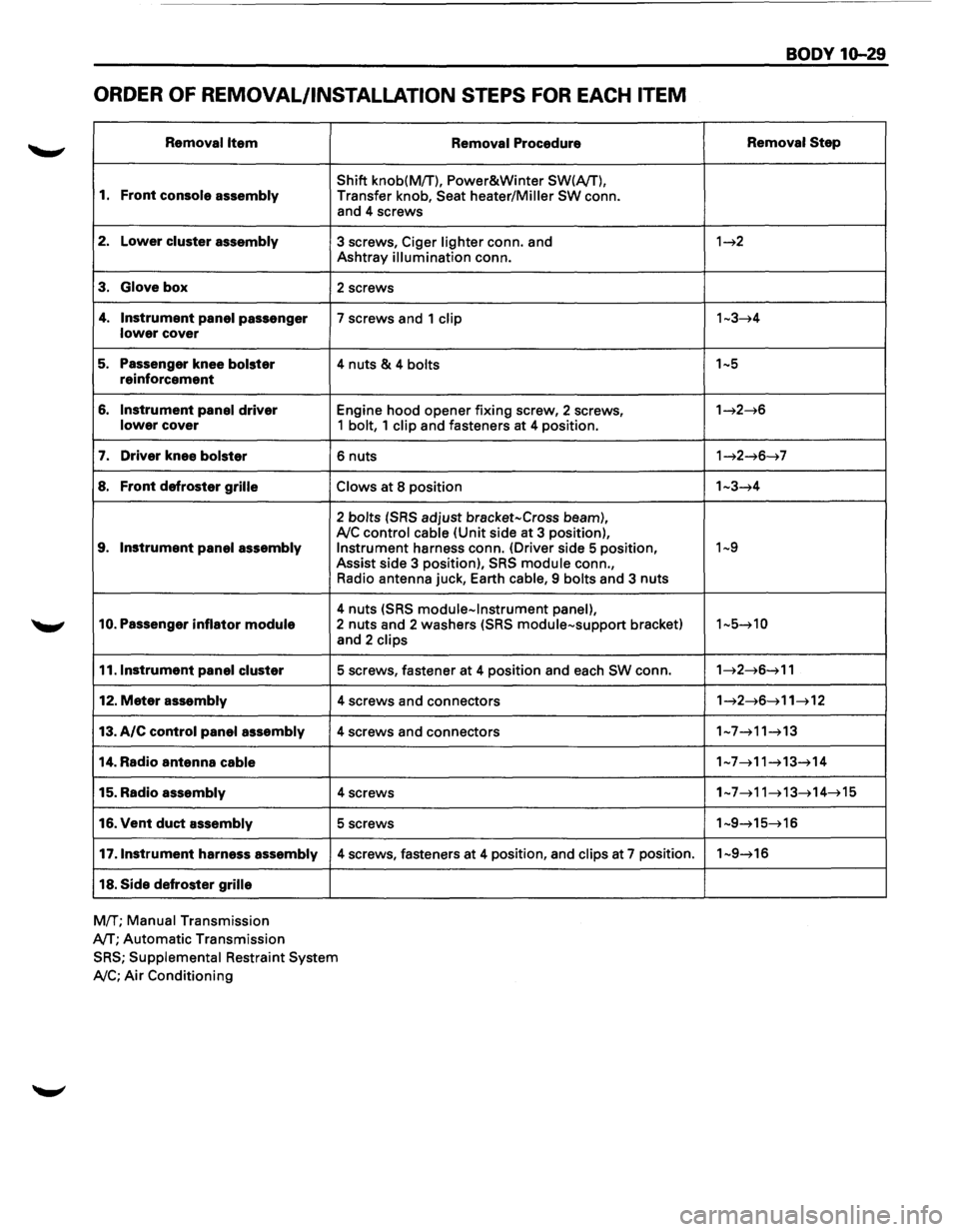
ORDER OF REMOVAL/INSTALLATION STEPS FOR EACH ITEM
Removal Item
1. Front console assembly
2. Lower cluster assembly
3. Glove box
4. Instrument panel passenger lower cover
5. Passenger knee bolster reinforcement
6. Instrument panel driver lower cover
7. Driver knee bolster
8. Front defroster grille
9. Instrument panel assembly
10. Passenger inflator module
11.1nstrument panel cluster
12. Meter assembly
13. A/C control panel assembly
14. Radio antenna cable
15. Radio assembly
16. Vent duct assembly
17 .Instrument harness assembly
18. Side defroster grille
MfT; Manual Transmission
A/T;
Automatic Transmission Removal
Procedure
Shift
knob(MfT), Power&Winter SW(A/T),
Transfer knob, Seat heater/Miller SW conn.
and 4 screws
3 screws, Ciger lighter conn. and
Ashtray illumination conn.
2 screws
7 screws and 1 clip
4 nuts & 4 bolts
Engine hood opener fixing screw, 2 screws, 1 bolt, 1 clip and fasteners at 4 position.
6 nuts
Claws at 8 position
2 bolts (SRS adjust bracket-Cross beam), A!C control cable (Unit side at 3 position), Instrument harness conn. (Driver side 5 position,
Assist side 3 position), SRS module conn.,
Radio antenna juck, Earth
cable, 9 bolts and 3 nuts
4 nuts (SRS module-Instrument panel), 2 nuts and 2 washers (SRS module-support bracket)
and 2 clips
5 screws, fastener at 4 position and each SW conn.
4 screws and connectors
4 screws and connectors
4 screws
5 screws
4 screws, fasteners at 4 position, and clips at 7 position.
SRS; Supplemental Restraint System
A!C; Air Conditioning
BODY 10-29
Removal Step
1~2
1~3~4
1~5
1~2~6
1~2~6~7
1-3~4
1~9
1-5~10
1~2~6~11
1~2~6~11~12
1-7~11~13
1-7~11~13~14
1~7~11~13~14~15
1-9~15~16
1-9~16
Page 1913 of 1928

CONTENTS
APPENDIX B-1
PAGE
Park ........................................................................\
....... B-3
Reverse . .")
APPENDIX B
HYDRAULIC CIRCUIT DIAGRAM
(Automatic Transmission)
CONTENTS
APPENDIX B-1
PAGE
Park ........................................................................\
....... B-3
Reverse . . . . . . . . . . . . . . . . . . . . . . . . . . . . . . . . . . . . . . . . . . . . . . . . . . . . . . . . . . . . . . . . . . . . . . . . . . .
B-5
Neutral . . . . . . . . . . . . . . . . . . . . . . . . . . . . . . . . . . . . . . . . . . . . . . . . . . . . . . . . . . . . . . . . . . . . . . . . . . . . B-6
Drive -Fourth Gear (Converter Clutch Applied} . . . . . . . . . . . . . . . . . . . . . . . . . . . . . . . . . . . . . . . B-6
Drive -Third Gear (Converter Clutch Applied} . . . . . . . . . . . . . . . . . . . . . . . . . . . . . . . . . . . . . . . . B-1
Drive -Third Gear (Converter Clutch Released} . . . . . . . . . . . . . . . . . . . . . . . . . . . . . . . . . . . . . . . B-8
Drive -Second Gear . . . . . . . . . . . . . . . . . . . . . . . . . . . . . . . . . . . . . . . . . . . . . . . . . . . . . . . . . . . . . . . . B-9
Drive -First Gear . . . . . . . . . . . . . . . . . . . . . . . . . . . . . . . . . . . . . . . . . . . . . . . . . . . . . . . . . . . . . . . . . . . B-1 0
3rd -Third Gear (Converter Clutch Released} . . . . . . . . . . . . . . . . . . . . . . . . . . . . . . . . . . . . . . . . . B-11
2nd -Second Gear . . . . . . . . . . . . . . . . . . . . . . . . . . . . . . . . . . . . . . . . . . . . . . . . . . . . . . . . . . . . . . . . . B-12
1st -First Gear . . . . . . . . . . . . . . . . . . . . . . . . . . . . . . . . . . . . . . . . . . . . . . . . . . . . . . . . . . . . . . . . . . . . . B-13