display ISUZU TROOPER 1995 Workshop Manual
[x] Cancel search | Manufacturer: ISUZU, Model Year: 1995, Model line: TROOPER, Model: ISUZU TROOPER 1995Pages: 1928
Page 411 of 1928
4-WHEEL ANTILOCK BRAKE SYSTEM (ABS) 5A4-1
SECTION 5A4
'--' 4-WHEEL ANTILOCK BRAKE SYSTEM (ABS)
CAUTION
All
brake attaching fasteners are an important attaching part in that they could affect performance of
vital parts and systems, and/or could result in major repair expense. They must be replaced with one
of the same part number or with an equivalent part if replacement becomes necessary. Do not use
replacement parts
of lesser quality or substitute design. Torque values must be used as specified
during reassembly to assure proper retention of these parts.
CONTENTS
General Description .................... 5A4-3
System Components ................. 5A4-3
Electronic Brake
Control Module ·
(EBCM) .......................... 5A4-3
Hydraulic Unit ...................... 5A4-3
ABS Warning Light .................. 5A4-4
Wheel
Speed Sensor ................. 5A4-4
G-Sensor
........................... 5A4-4
Normal and Antilock Braking .......... 5A4-4
Brake Pedal Travel
................... 5A4-4
Abbreviation ........................ 5A4-4
Diagnosis
............................. 5A4-5
General
Information ................. 5A4-5
ABS
System Service Precautions ....... 5A4-5
Computer System Service
Precautions
....................... 5A4-5
General Service Precautions
........... 5A4-5
Note on lntermittents ................ 5A4-6
Test Driving ABS Complaint Vehicles ... 5A4-6
II ABS11 Warning Light ................ 5A4-6
Normal Operation ................... 5A4-6
Basic
Diagnostic Flow Chart ........... 5A4-7
Basic
Inspection Procedure ............ 5A4-8
TECH 1
TOOL. ......................... 5A4-10
1. What can be done with TECH 1 ...... 5A4-10
2. How to Use TECH 1 ................ 5A4-11
3. Explanation of Modes .............. 5A4-15
Mode FO: Data List ................... 5A4-16
Mode F2: Trouble Code ............... 5A4-18
Mode F3: Snapshot .................. 5A4-19
Mode F4: Clear Code ................. 5A4-20
Mode F5: Actuator Test ............... 5A4-21
Mode F6: Wheel Sensors ............. 5A4-31
Pin-Out Checks ........................ 5A4-33
Circuit Diagram ..................... 5A4-34
Part Location ....................... 5A4-37
Symptom Diagnosis .................... 5A4-38
CHART A-1 1) ABS Works Frequently
but Vehicle does not Decelerate ...... 5A4-39
CHART TA-1 1) ABS Works Frequently
but Vehicle does not Decelerate ...... 5A4-40
CHART A-2 2) Uneven Braking Occurs
while ABS Works .................. 5A4-41
CHART TA-2 2) Uneven Braking Occurs
while ABS Works .................. 5A4-42
CHART A-3, T A-3 3) The Wheels are
Locked
........................... 5A4-43
CHART A-4 4) Brake Pedal Feel is
Abnormal ........................ 5A4-44
CHART A-5 , T A-5 5) Braking Sound
(from Hydraulic Unit) is Heard while
not Braking ....................... 5A4-45
Diagnosis by 11 ABS11 Warning Light
Illumination Pattern .................. 5A4-46
Diagnostic Trouble Codes (DTCs) ....... 5A4-47
1. How to Display and Erase DTCs ... 5A4-47
2. Diagnostic Trouble Codes ........ 5A4-49
CHART B-1 With the Key in the ON
Position (before Starting the Engine),
Warning Light (W /L) is not
•
Actuated ........................ 5A4-50
CHART B-2 II ABSII Light Flashes
Twice with Key ON ................ 5A4-51
CHART B-3 EBCM Abnormality (Diagnostic
Trouble Code 14) .................. 5A4-52
CHART B-4 Power Voltage Drop (Diagnostic
Trouble Code 15) .................. 5A4-53
CHART B-5 G-Sensor Circuit (Diagnostic
Trouble Code 21) .................. 5A4-54
CHART B-6 Brake Switch Trouble
(Diagnostic Trouble Code 22) ........ 5A4-55
CHART B-7 Abnormal Transmission Input
(A/T Modei)(Diagnostic Trouble
Code 23) ......................... 5A4-56
CHART B-7 Abnormal Transmission Input
(M/T Modei)(Diagnostic Trouble
Code 23) ......................... 5A4-57
CHART B-8 Hydraulic Unit (HU) Pump
Motor and Motor Relay Circuit
(Diagnostic Trouble Code 32) ........ 5A4-58
CHART B-9 Solenoid Valve Abnormality
(Diagnostic Trouble Code 41, 42,
& 44) ............................ 5A4-59
CHART B-10 Valve Relay Abnormality
(Diagnostic Trouble Code 45) ........ 5A4-60
Page 422 of 1928
5A4-12 4-WHEEL ANTILOCK BRAKE SYSTEM (ABS)
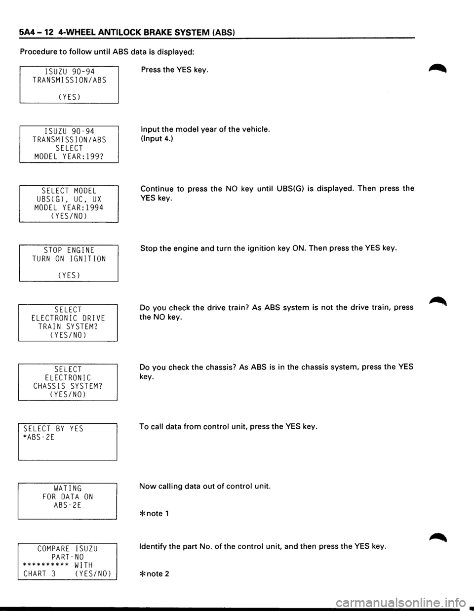
Procedure to follow until ABS data is displayed:
ISUZU 90-94
TRANSMISSION/ASS
C YES)
ISUZU 90-94
TRANSMISSION/ASS
SELECT
MODEL YEAR:l99?
SELECT MODEL
UBSCG), UC, UX
MODEL YEAR:l994
CYES/NO)
STOP ENGINE
TURN ON IGNITION
C YES)
SELECT
ELECTRONIC DRIVE
TRAIN SYSTEM?
CYES/NO)
SELECT
ELECTRONIC
CHASSIS SYSTEM?
CYES/NO)
SELECT BY YES
*ABS-2E
WATING
FOR DATA ON
ABS-2E
COMPARE ISUZU
PART-NO
********** WITH
CHART 3 CYES/NO)
Press the YES key.
Input the model year of the vehicle.
(Input
4.)
Continue to press the NO key until UBS(G) is displayed. Then press the
YES key.
Stop the engine and turn the ignition key
ON. Then press the YES key.
Do you check the drive train? As ABS system is
not the drive train, press
the
NO key.
Do you check the chassis? As ABS
is in the chassis system, press the YES
key.
To
call data from control unit, press the YES key.
Now calling data out of control unit.
Identify the part No. of the control unit, and then press the YES key.
Page 423 of 1928
ABS-2E
NO TROUBLE CODE
SELECT MODE
FO:DATA LIST
F1: NOT USED
F2:TROUBLE CODE
SELECT MODE
F3:SNAP SHOT
F4:CLEAR CODE
F5:ACTUATOR TEST
SELECT MODE
F6:WHEEL SENSORS
*note 1
ABS-2E
NO DATA!
CHECK ALDL CONN.
SEE CHART 1
4-WHEEL ANTILOCK BRAKE SYSTEM (ABS) 5A4-13
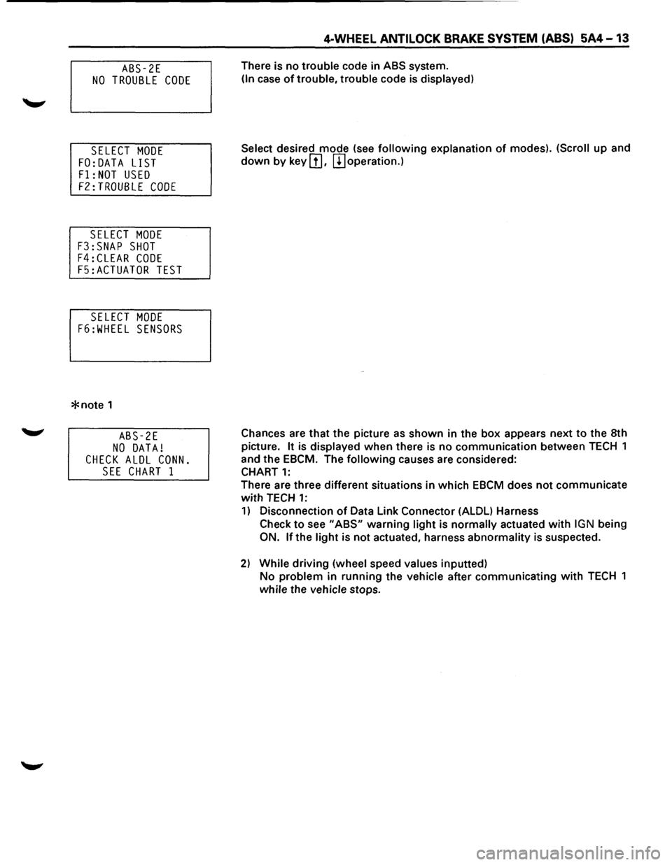
There is no trouble code in ABS system.
(In case of trouble, trouble code is displayed)
Select
desired mode (see following explanation of modes). (Scroll up and
down by key III. m operation.)
Chances are
that the picture as shown in the box appears next to the 8th
picture.
It is displayed when there is no communication between TECH 1
and the EBCM. The
following causes are considered:
CHART
1:
There are three different situations in which EBCM does not communicate
with TECH 1:
1) Disconnection of Data Link Connector (ALDL) Harness
Check
to see "ABS" warning light is normally actuated with IGN being
ON. lfthe light is not actuated, harness abnormality is suspected.
2) While driving (wheel speed values inputted)
No problem in running the vehicle after communicating with TECH 1
while the vehicle stops.
Page 424 of 1928
5A4 -14 4-WHEEL ANTILOCK BRAKE SYSTEM (ABS)
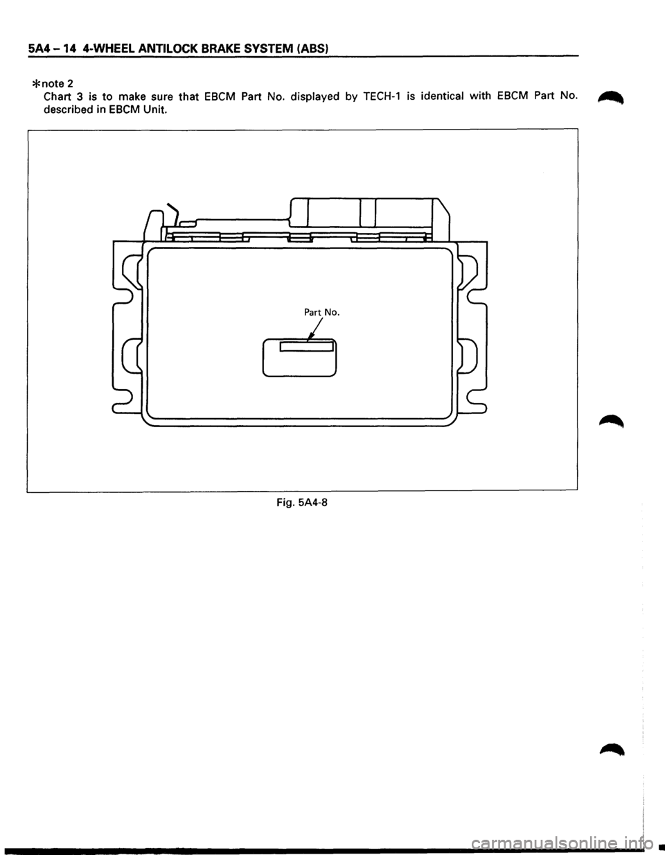
*note 2
Chart 3 is to make sure that EBCM Part No. displayed by TECH-1 is identical with EBCM Part No. ~
described in EBCM Unit.
Part No.
I
Fig. 5A4-8
•
Page 425 of 1928
4-WHEEL ANTILOCK BRAKE SYSTEM (ABS) 5A4-15
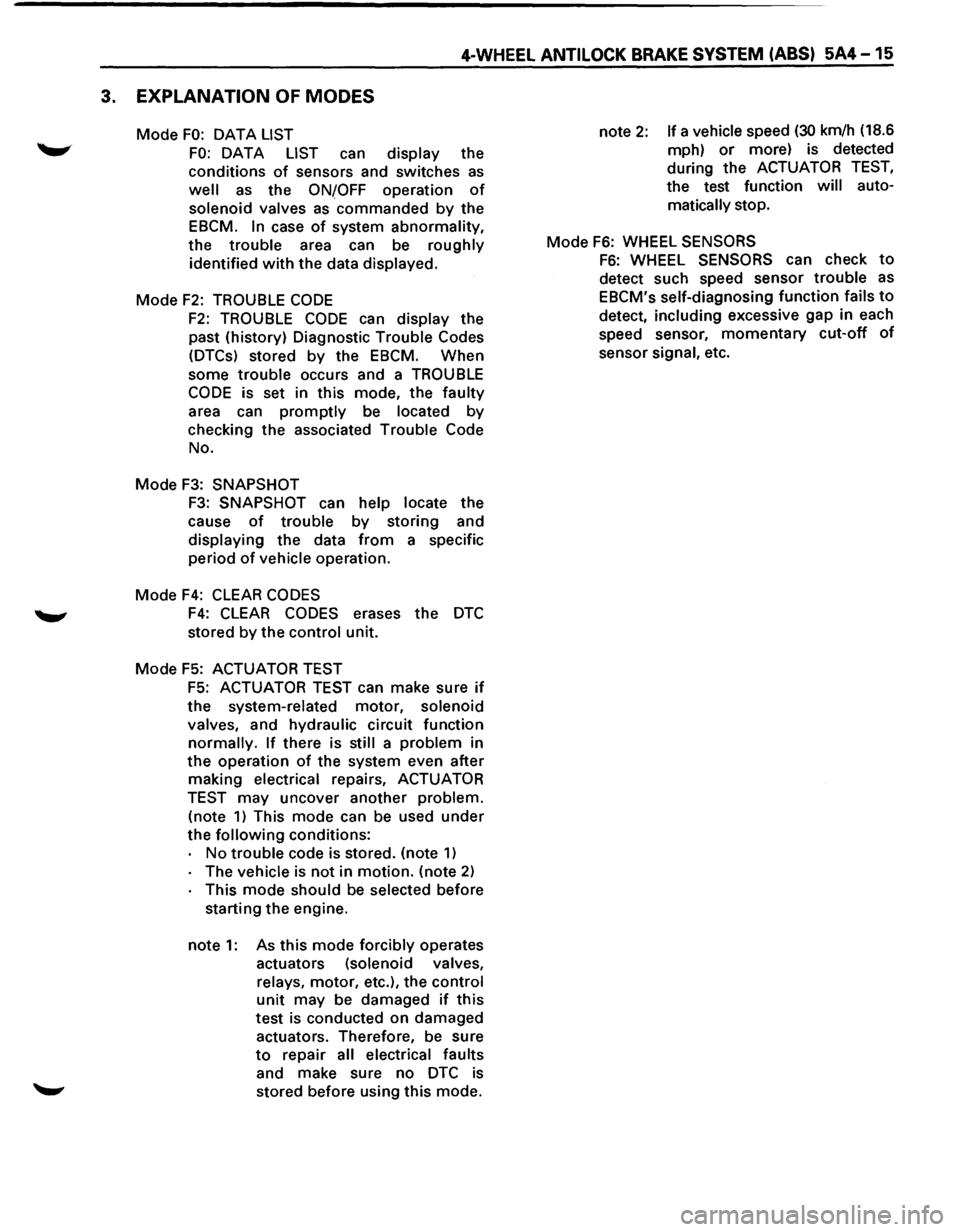
3. EXPLANATION OF MODES
Mode FO: OAT A LIST
FO: DATA LIST can display the
conditions
of sensors and switches as
well as the ONfOFF operation of
solenoid valves as commanded by the
EBCM.
In case of system abnormality,
the trouble area can be roughly
identified
with the data displayed.
Mode
F2: TROUBLE CODE
F2: TROUBLE CODE can display the
past (history) Diagnostic Trouble Codes
(DTCs) stored
by the EBCM. When
some
trouble occurs and a TROUBLE
CODE is set in this mode, the faulty
area can
promptly be located by
checking the associated Trouble Code
No.
Mode
F3: SNAPSHOT
F3: SNAPSHOT can help locate the
cause
of trouble by storing and
displaying the data
from a specific
period
of vehicle operation.
Mode
F4: CLEAR CODES
F4: CLEAR CODES erases the DTC
stored by the control unit.
Mode F5: ACTUATOR TEST
F5: ACTUATOR TEST can make sure if
the system-related motor, solenoid
valves, and hydraulic circuit function
normally. If there is still a problem in
the operation of the system even after
making electrical repairs, ACTUATOR
TEST may uncover another problem.
(note
1) This mode can be used under
the
following conditions:
No
trouble code is stored. (note 1)
The vehicle is not in motion. (note 2)
This mode should be selected before
starting the engine.
note
1: As this mode forcibly operates
actuators (solenoid valves,
relays, motor, etc.), the control
unit may be damaged if this
test
is conducted on damaged
actuators. Therefore, be sure
to repair all electrical faults
and make sure no
DTC is
stored before using this mode. note
2: If a vehicle speed (30 km/h
(18.6
mph)
or more) is detected
during the ACTUATOR
TEST,
the test function will auto
matically stop.
Mode
F6: WHEEL SENSORS
F6: WHEEL SENSORS can check to
detect such speed sensor trouble as
EBCM's self-diagnosing function fails to
detect, including excessive gap in each
speed sensor,
momentary cut-off of
sensor signal, etc.
Page 426 of 1928
5A4-16 4-WHEEL ANTILOCK BRAKE SYSTEM (ABS)
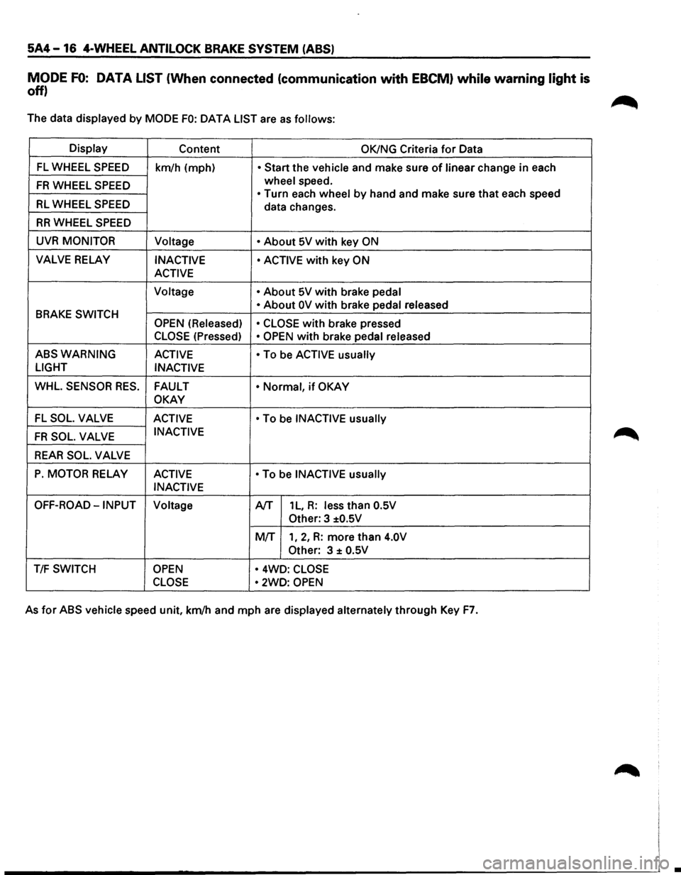
MODE FO: DATA LIST (When connected (communication with EBCM) while warning light is
off)
The data displayed by MODE FO: OAT A LIST are as follows:
Display Content OK/NG Criteria for Data
FL WHEEL SPEED km/h (mph) • Start the vehicle and make sure of linear change in each
FR WHEEL SPEED wheel speed.
• Turn each wheel by hand and make sure that each speed RL WHEEL SPEED data changes.
RR WHEEL SPEED
UVR MONITOR
Voltage • About 5V with key ON
VALVE RELAY INACTIVE • ACTIVE with key ON
ACTIVE
Voltage •
About 5V with brake pedal
BRAKE SWITCH • About OV with brake pedal
released
OPEN (Released)
• CLOSE
with brake pressed
CLOSE (Pressed) • OPEN with brake pedal released
ABSWARNING ACTIVE
• To be ACTIVE usually
LIGHT
INACTIVE
WHL. SENSOR RES. FAULT • Normal, if OKAY
OKAY
-FL SOL. VALVE ACTIVE • To be INACTIVE usually
FR SOL. VALVE INACTIVE
REAR SOL. VALVE
P. MOTOR RELAY ACTIVE • To be INACTIVE usually
INACTIVE
OFF-ROAD-INPUT Voltage A/T 1 L, R: less than O.SV
Other: 3 ±O.SV
MIT 1, 2, R: more than 4.0V
Other:
3 ± O.SV
T/F SWITCH OPEN • 4WD: CLOSE
CLOSE •
2WD: OPEN
As for ABS vehicle speed unit, km/h and mph are displayed alternately through Key F7.
•
Page 427 of 1928
4-WHEEL ANTILOCK BRAKE SYSTEM (ABS) 5A4-17
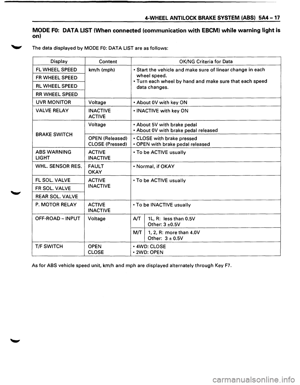
MODE FO: DATA LIST (When connected (communication with EBCM) while warning light is
on)
._,. The data displayed by MODE FO: DATA LIST are as follows:
Display
Content OK/NG Criteria for Data
FL WHEEL SPEED
km/h (mph) • Start the vehicle and make sure of linear change in each
FR WHEEL SPEED wheel speed.
• Turn each wheel by hand and make sure that each speed RL WHEEL SPEED data changes.
RR WHEEL SPEED
UVR MONITOR Voltage • About OV with key ON
VALVE RELAY INACTIVE • INACTIVE with key ON
ACTIVE
Voltage • About 5V with brake pedal
BRAKE
SWITCH • About OV with brake
pedal released
OPEN (Released) • CLOSE with brake pressed
CLOSE (Pressed) • OPEN with brake pedal released
ABSWARNING ACTIVE • To be ACTIVE usually
LIGHT
INACTIVE
WHL.
SENSOR RES. FAULT • Normal, if OKAY
OKAY
FL SOL. VALVE ACTIVE • To be ACTIVE usually
FR SOL. VALVE INACTIVE
REAR SOL. VALVE
P. MOTOR RELAY
ACTIVE • To be INACTIVE usually
INACTIVE
OFF-ROAD-INPUT Voltage A/T 1 L, R: less than 0.5V
Other:
3 ±0.5V
MIT
1, 2, R: more than 4.0V
Other:
3 ± 0.5V
T/F SWITCH OPEN • 4WD: CLOSE
CLOSE •
2WD: OPEN
As for ABS vehicle speed unit, km/h and mph are displayed alternately through Key F7.
Page 428 of 1928
5A4-18 4-WHEEL ANTILOCK BRAKE SYSTEM (ABS)
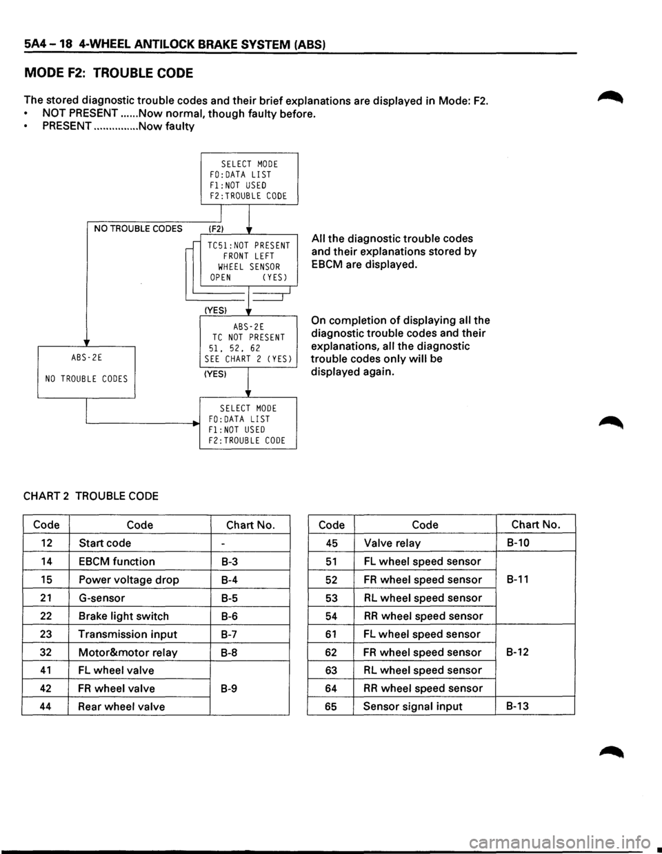
MODE F2: TROUBLE CODE
The stored diagnostic trouble codes and their brief explanations are displayed in Mode: F2.
NOT PRESENT ...... Now normal, though faulty before.
PRESENT ............... Now faulty
NO TROUBLE CODES
ABS-2E
NO TROUBLE CODES
CHART 2 TROUBLE CODE
Code Code
12 Start code
14 EBCM function
15 Power voltage drop
21 G-sensor
22 Brake light switch
23 Transmission input
32 Motor&motor relay
41 FL wheel valve
42 FR wheel valve
44 Rear wheel valve
SELECT MODE FO:DATA LIST
F1: NOT USED F2:TROUBLE CODE
I
l (F2)
TC51:NOT PRESENT FRONT LEFT
WHEEL SENSOR OPEN (YESJ
(YES) J--_j
ABS-2E TC NOT PRESENT
51. 52, 62 SEE CHART 2 (YESJ
(YES)
l
SELECT MODE FO: DATA LIST
Fl:NOT USED F2:TROUBLE CODE
Chart No.
-
B-3
B-4
B-5
B-6
B-7
B-8
B-9
All the diagnostic trouble codes
and
their explanations stored by
EBCM are displayed.
On completion of displaying all the
diagnostic trouble codes and
their
explanations, all the diagnostic
trouble codes
only will be
displayed again.
Code Code
45 Valve relay
51 FL wheel speed sensor
52 FR wheel speed sensor
53 RL wheel speed sensor
54 RR wheel speed sensor
61 FL wheel speed sensor
62 FR wheel speed sensor
63 RL wheel speed sensor
64 RR wheel speed sensor
65 Sensor signal input
Chart No.
B-10
B-11
B-12
B-13
•
Page 429 of 1928
4-WHEEL ANTILOCK BRAKE SYSTEM (ABS) 5A4-19
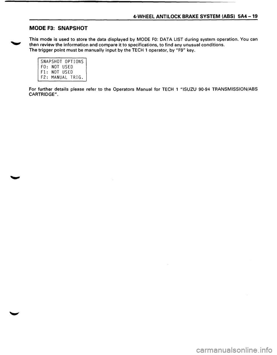
MODE F3: SNAPSHOT
This mode is used to store the data displayed by MODE FO: DATA LIST during system operation. You can
then review the information and compare it to specifications, to find any unusual conditions.
The
trigger point must be manually input by the TECH 1 operator, by "F9" key.
SNAPSHOT OPTIONS
FO: NOT USED
Fl: NOT USED
F2: MANUAL TRIG.
For further details please refer to the Operators Manual for TECH 1 "ISUZU 90-94 TRANSMISSION/ASS
CARTRIDGE".
Page 432 of 1928
5A4-22 4-WHEEL ANTI LOCK BRAKE SYSTEM (ABS)
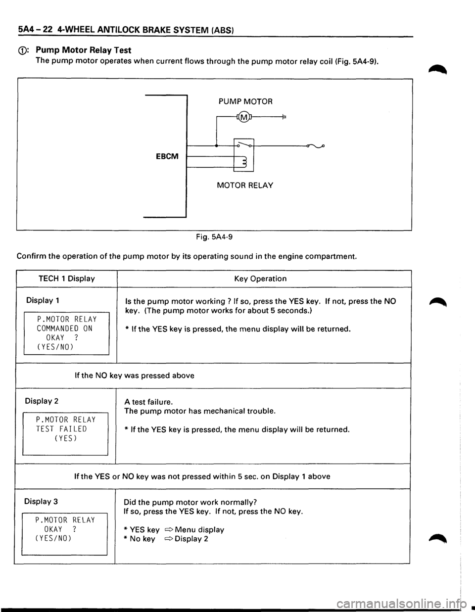
(j): Pump Motor Relay Test
The pump motor operates when current flows through the pump motor relay coil (Fig. 5A4-9).
PUMP
MOTOR
~ II
....----
EBCM ~ .____
MOTOR RELAY
Fig. 5A4-9
Confirm the operation of the pump motor by its operating sound in the engine compartment.
TECH 1 Display Key Operation
Display 1 Is the pump motor working ? If so, press the YES key. If not, press the NO
key. (The pump motor works for about 5 seconds.)
P.MOTOR RELAY
COMMANDED ON * If the YES key is pressed, the menu display will be returned.
OKAY ?
(YES/NO)
If the NO key was pressed above
Display 2
A test failure.
The pump motor has mechanical trouble.
P.MOTOR RELAY
TEST FAILED * If the YES key is pressed, the menu display will be returned.
(YES)
If the YES or NO key was not pressed within 5 sec. on Display 1 above
Display 3
Did the pump motor work normally?
If so, press the YES key. If not, press the NO key.
P.MOTOR RELAY
OKAY ? * YES key c:::> Menu display
(YES/NO) *No key c:::>Display 2
•