automatic transmission ISUZU TROOPER 1995 Workshop Manual
[x] Cancel search | Manufacturer: ISUZU, Model Year: 1995, Model line: TROOPER, Model: ISUZU TROOPER 1995Pages: 1928
Page 1078 of 1928
7A-206 AUTOMATIC TRANSMISSION (4L30-E)
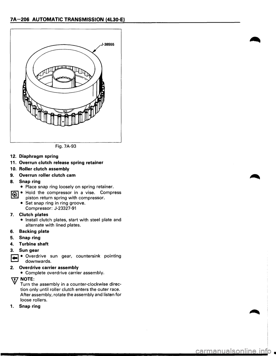
Fig. 7A-93
12. Diaphragm spring
11. Overrun clutch release spring retainer
1 0. Roller clutch assembly
9. Overrun roller clutch cam
8. Snap ring
• Place snap ring loosely on spring retainer.
I®J • Hold the compressor in a vise. Compress
piston return spring
with compressor.
• Set snap ring in ring groove.
Compressor: J-23327-91
7. Clutch plates
• Install clutch plates, start with steel plate and
alternate with lined plates.
6. Backing plate
5. Snap ring
4. Turbine shaft
3. Sun gear
r=l • Overdrive sun gear, countersink pointing
t=.l downwards.
2. Overdrive carrier assembly
• Complete overdrive carrier assembly.
\i7 NOTE:
VI Turn the assembly in a counter-clockwise direc
tion
only until roller clutch enters the outer race.
After assembly, rotate the assembly and listen for
loose rollers.
1. Snap ring
•
Page 1079 of 1928
AUTOMATIC TRANSMISSION (4L30-E) 7 A-207
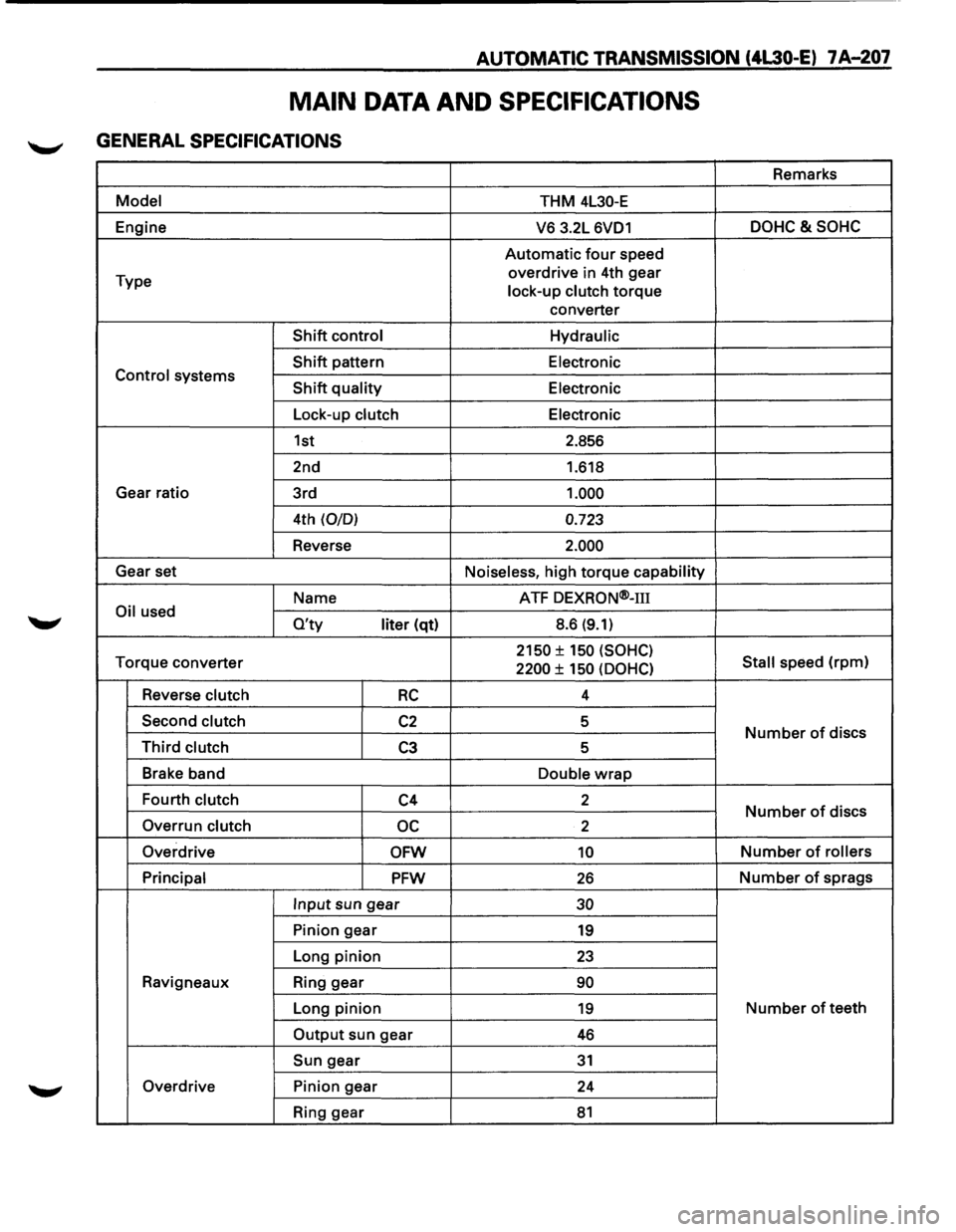
MAIN DATA AND SPECIFICATIONS
GENERAL SPECIFICATIONS
Remarks
Model THM 4L30-E
Engine
V6 3.2L 6VD1 DOHC&SOHC
Automatic four speed
Type overdrive
in 4th gear
lock-up clutch
torque
converter
Shift control Hydraulic
Shift pattern
Electronic Control systems Shift quality Electronic
Lock-up clutch Electronic
1st 2.856
2nd 1.618
Gear ratio
3rd
1.000
4th (0/0) 0.723
Reverse 2.000
Gear set
Noiseless, high torque capability
Name ATF
DEXRON®-m
Oil used O'ty liter (qt) 8.6 (9.1)
Torque
converter 2150 ± 150 (SOHC)
Stall speed (rpm) 2200 ± 150 (OOHC)
Reverse clutch RC 4
Second clutch
C2 5 Number of discs Third clutch C3 5
Brake band
Double
wrap
Fourth clutch C4 2 Number of discs
Overrun clutch oc 2
Overdrive
OFW 10 Number of rollers
Principal
PFW 26 Number of sprags
Input sun gear 30
Pinion gear 19
Long pinion 23
Ravigneaux Ring gear 90
Long pinion 19 Number of teeth
Output sun gear 46
Sun gear 31
Overdrive Pinion gear
24
Ring gear
81
Page 1080 of 1928
7 A-208 AUTOMATIC TRANSMISSION (4l30-E)
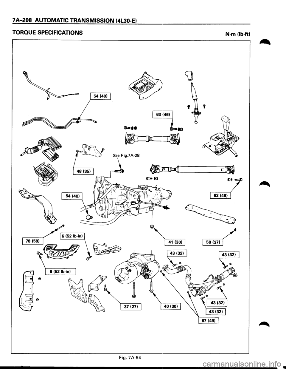
TORQUE SPECIFICATIONS
•
/r6 (52 lb·in)
~-L
~
Fig. 7A-94
N-m (lb-ft)
'
o;
JJI/
~
Page 1081 of 1928
AUTOMATIC TRANSMISSION (4L30-E) 7A-209
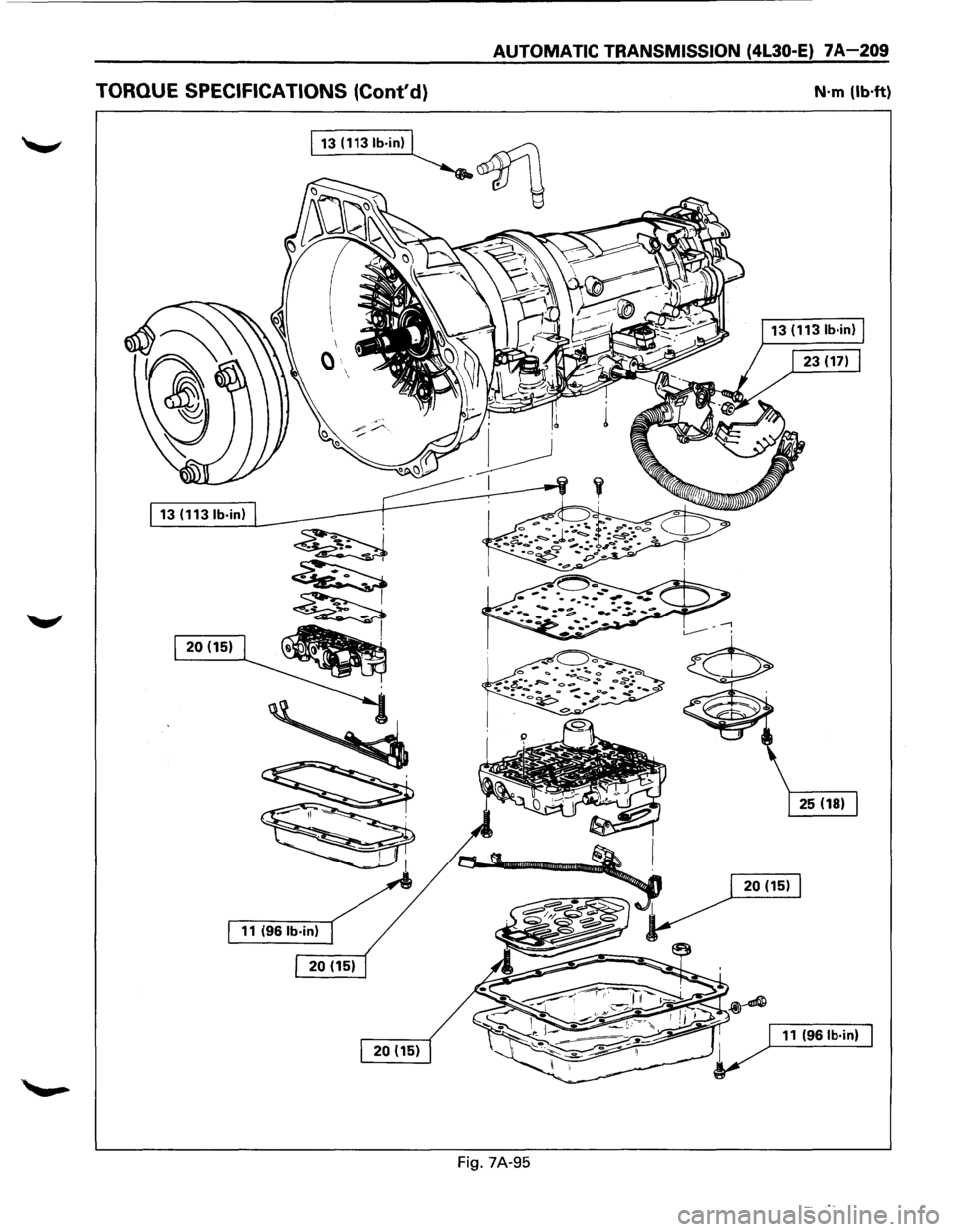
TORQUE SPECIFICATIONS (Cont'd} N·m (lb·ft)
13 (1131b·in)
~
~
120(1511~
·~
Fig. 7A-95
Page 1082 of 1928
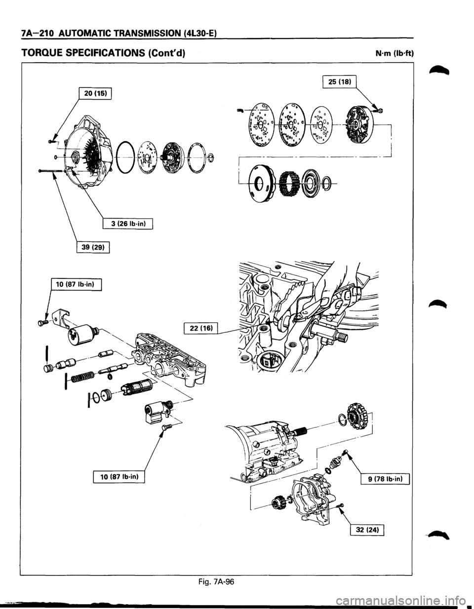
7A-210 AUTOMATIC TRANSMISSION (4L30-E)
TORQUE SPECIFICATIONS (Cont'd) N·m (lb·ft)
______ j
10 (87 lb·in)
10
(87 lb·in) 9 (78 lb·in)
Fig. 7A-96
Page 1083 of 1928
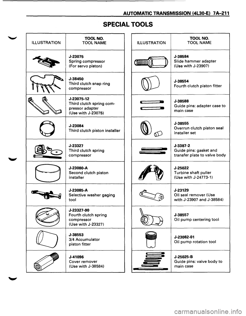
AUTOMATIC TRANSMISSION (4L30-E) 7 A-211
SPECIAL TOOLS
TOOL NO. TOOL
NO.
ILLUSTRATION
TOOL NAME ILLUSTRATION TOOL NAME
~
J-23075
Spring compressor
(For
servo piston) 011mwn ~
J-38584
Slide hammer adapter
(Use
with J-23907)
J-38450
Third clutch snap ring
,,"
compressor @]
J-38554
Fourth clutch piston
fitter
'~
J-23075-12
Third clutch spring com-
pressor adapter
(Use
with J-23075)
'
• J-38588
' •
Guide pins: adapter case to
main case
0
J-23084
Third clutch piston installer ~\1D
J-38555
Overrun
clutch piston seal
installer
set
~~~
J-23327
Third clutch spring
(t compressor
J-3387-2 Guide pins: gasket and
transfer plate to valve
body
8
J-23080-A
Second clutch piston
installer ~
J-25022
Turbine shaft puller
(Use with J-24773-1)
··~
J-23085-A
Selective washer gaging
tool ~
J-23129
Oil seal remover (Use
with J-23907 and J-38584)
®
J-23327-90
Fourth
clutch spring
compressor
(Use with J-23327) ~
J-38557
Oil pump centering tool
ra
J-38553
3/4
Accumulator
piston fitter ~
J-23082-01 Oil
pump rotation tool
~
J-41096 Cover remover
(Use
with J-38584)
~ J-25025-B
Guide pins: valve body to
main case
Page 1084 of 1928
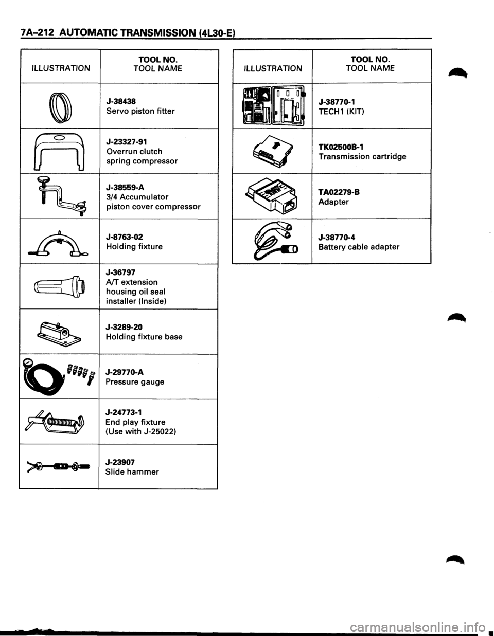
7A-212 AUTOMATIC TRANSMISSION (4L30-E)
TOOL NO.
ILLUSTRATION TOOL
NAME
0
J-38438
Servo piston
fitter
frO
J-23327-91
Overrun
clutch
spring compressor
~
J-38559-A
3/4
Accumulator
piston cover compressor
~
J-8763-02
Holding fixture
J-36797
@jtD A/T extension
housing
oil seal
installer (Inside)
~
J-3289-20
Holding fixture base
~''''I
J-29770-A
Pressure gauge
~
J-24773-1
End
play fixture
(Use
with J-25022)
~ 1:-i-J-23907
Slide hammer
ILLUSTRATION TOOL
NO.
TOOL NAME
J-38770-1
TECH1 (KIT)
TK02500B-1
Transmission cartridge
TA02279-B Adapter
J-38770-4 Battery
cable adapter
•
Page 1085 of 1928
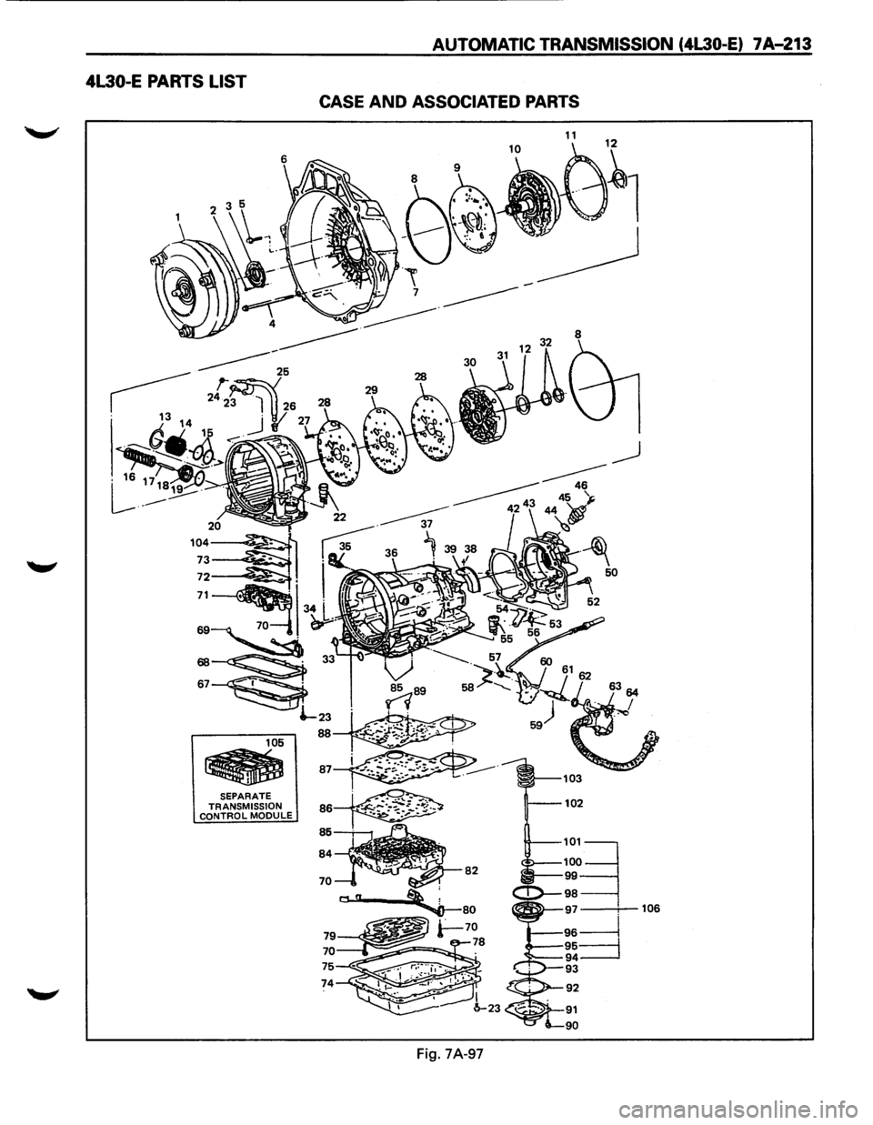
AUTOMATIC TRANSMISSION (4L30 E)
--------~CCAJSE AND -7A-213 ASSOCIATED PARTS
4L30-E
PARTS LIST
SEPARATE
C~~f~J~ISSION MODULE
74
103
102
50
106
Page 1086 of 1928
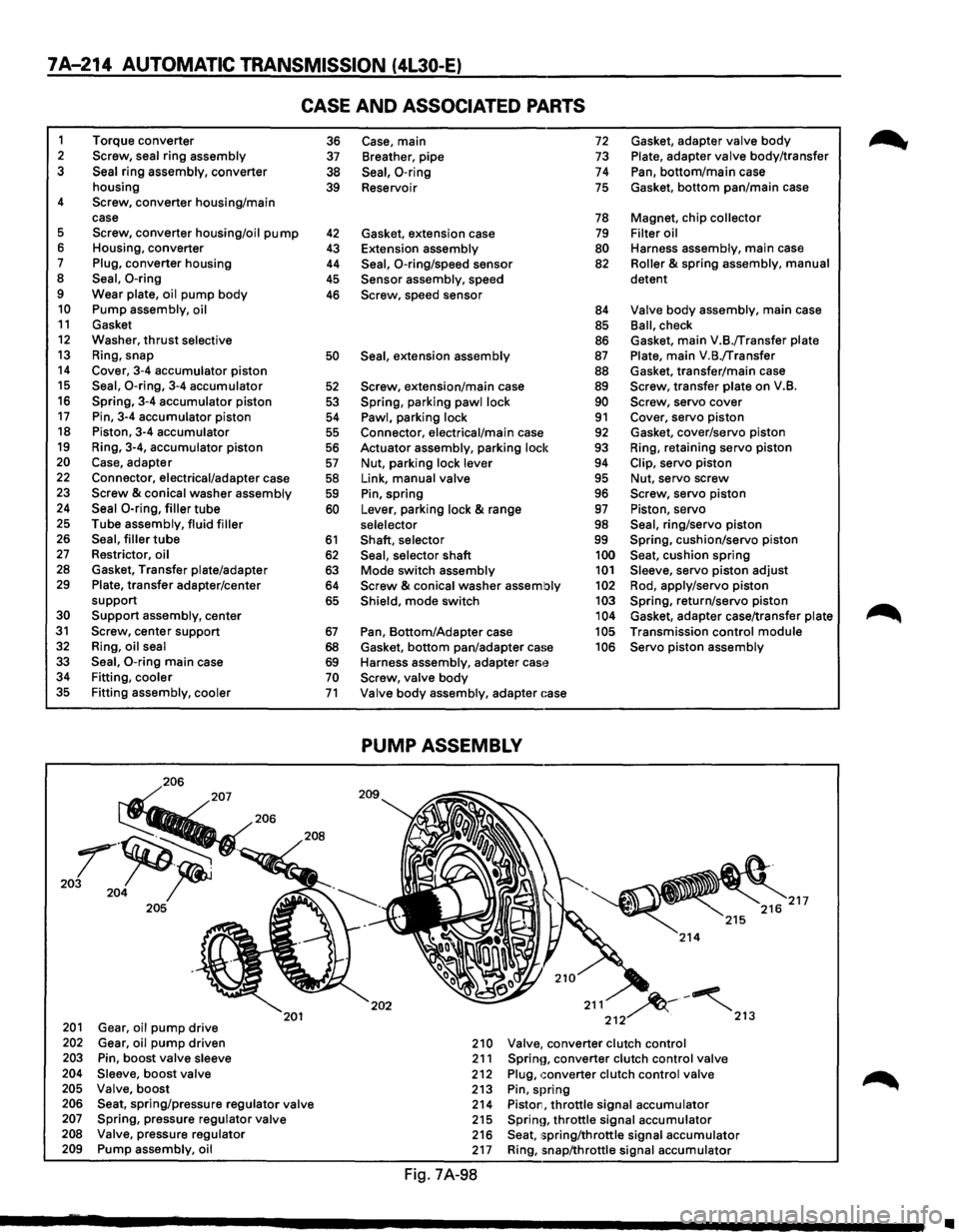
7A-214 AUTOMATIC TRANSMISSION (4L30-E)
CASE AND ASSOCIATED PARTS
1 Torque converter 2 Screw, seal ring assembly 3 Seal ring assembly, converter
housing
4 Screw, converter housing/main
case
5 Screw, converter housing/oil pump 6 Housing, converter 7 Plug, converter housing 8 Seal, 0-ring 9 Wear plate, oil pump body 10 Pump assembly, oil 11 Gasket 12 Washer, thrust selective 13 Ring, snap 14 Cover, 3-4 accumulator piston 15 Seal, 0-ring, 3-4 accumulator 16 Spring, 3-4 accumulator piston 17 Pin, 3-4 accumulator piston 18 Piston, 3-4 accumulator 19 Ring, 3-4, accumulator piston 20 Case, adapter 22 Connector, electrical/adapter case 23 Screw & conical washer assembly 24 Seal 0-ring, filler tube 25 Tube assembly, fluid filler 26 Seal, filler tube 27 Restrictor, oil 28 Gasket, Transfer plate/adapter 29 Plate, transfer adapter/center
support
30 Support assembly, center 31 Screw, center support 32 Ring, oil seal
33 Seal, 0-ring main case 34 Fitting, cooler 35 Fitting assembly, cooler
206
201 Gear, oil pump drive 202 Gear, oil pump driven 203 Pin, boost valve sleeve 204 Sleeve, boost valve 205 Valve, boost
201
206 Seat, spring/pressure regulator valve 207 Spring, pressure regulator valve 208 Valve, pressure regulator 209 Pump assembly, oil
36 37
38
39
42 43
44
45
46
50
52
53
54
55
56
57
58 59
60
61
62 63 64
65
67
68 69 70 71
Case, main 72 Gasket, adapter valve body
Breather, pipe 73 Plate, adapter valve body/transfer
Seal, 0-ring 74 Pan, bottom/main case
Reservoir
75 Gasket, bottom pan/main case
78 Magnet, chip collector
Gasket, extension case
79 Filter oil
Extension assembly
80 Harness assembly, main case
Seal, 0-ring/speed sensor 82 Roller & spring assembly, manual
Sensor assembly, speed detent Screw, speed
sensor 84 Valve body assembly, main case
85 Ball, check
86 Gasket, main V.B./Transfer plate
Seal, extension assembly 87 Plate, main V.B./Transfer
88 Gasket, transfer/main case
Screw, extension/main case 89 Screw, transfer plate on V.B.
Spring, parking pawl lock 90 Screw, servo cover
Pawl, parking lock 91 Cover, servo piston Connector, electrical/main case 92 Gasket, cover/servo piston
Actuator assembly, parking lock
93 Ring, retaining servo piston
Nut, parking lock lever 94 Clip, servo piston
Link, manual valve 95 Nut, servo screw
Pin, spring 96 Screw, servo piston
Lever, parking lock
& range 97 Piston, servo
selelector 98 Seal, ring/servo piston
Shaft, selector 99 Spring, cushion/servo piston
Seal, selector shaft 100 Seat, cushion spring
Mode switch assembly 101 Sleeve, servo piston adjust
Screw & conical washer assembly 102 Rod, apply/servo piston
Shield, mode switch 103 Spring, return/servo piston 104 Gasket, adapter case/transfer plate
Pan, Bottom/Adapter case 105 Transmission control module
Gasket,
bottom pan/adapter ca!~e 106 Servo piston assembly
Harness assembly, adapter
cas'~ Screw, valve body
Valve body assembly, adapter ~:ase
PUMP ASSEMBLY
202 211 ~-~ 212 . 213
210 Valve, converter clutch control 211 Sprinn, converter clutch control valve 212 Plug, converter clutch control valve 213 Pin, spring 214 Piston, throttle signal accumulator 215 Sprinn, throttle signal accumulator 216 Seat, 1;pring/throttle signal accumulator 217 Ring, snap/throttle signal accumulator
Fig. 7A-98
~
•
Page 1087 of 1928
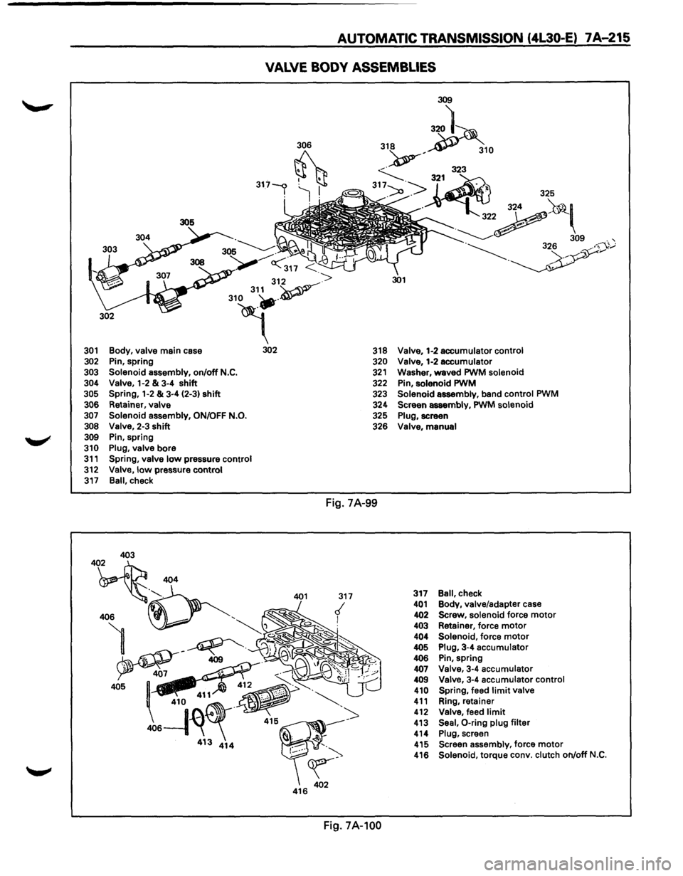
AUTOMATIC TRANSMISSION (4L30-E) 7A-215
VALVE BODY ASSEMBLIES
306
317-<:> . I ~ jl
<317 <
312 ->
310 31~v--
4" 301 Body, valve main case 302
302 Pin, spring
303 Solenoid assembly, on/off N.C. 304 Valve, 1-2 & 3-4 shift 305 Spring, 1-2 & 3-4 (2-3) shift
306 Retainer, valve 307 Solenoid assembly, ON/OFF N.O. 308 Valve, 2-3 shift 309 Pin, spring
310 Plug, valve bore 311 Spring, valve low pressure control
312 Valve, low pressure control 317 Ball, check
318 Valve, 1-2 accumulator control 320 Valve, 1-2 accumulator 321 Washer, waved PWM solenoid 322 Pin, solenoid PWM 323 Solenoid assembly, band control PWM 324 Screen assembly, PWM solenoid 325 Plug, screen 326 Valve, manual
Fig. 7A-99
Fig.
7A-100
317 Ball, check 401 Body, valve/adapter case 402 Screw, solenoid force motor 403 Retainer, force motor 404 Solenoid, force motor 405 Plug, 3-4 accumulator 406 Pin, spring 407 Valve, 3-4 accumulator 409 Valve, 3-4 accumulator control 410 Spring, feed limit valve 411 Ring, retainer 412 Valve, feed limit 413 Seal, 0-ring plug filter 414 Plug, screen 415 Screen assembly, force motor 416 Solenoid, torque conv. clutch on/off N.C.