air filter ISUZU TROOPER 1995 Owner's Manual
[x] Cancel search | Manufacturer: ISUZU, Model Year: 1995, Model line: TROOPER, Model: ISUZU TROOPER 1995Pages: 1928
Page 790 of 1928
6E2-94 DRIVEABILITY AND EMISSIONS
3. If there is no revolution per minute (rpm) drop
on one or more cylinders, or excessive
variation is drop, check
for spark on the
suspected
cylinder(s) using a shop
oscilloscope or with J 26792 (ST-125) spark
tester
or equivalent. If no spark, refer to
ENGINE ELECTRICAL (SECTION 6D) for
intermittent operation of miss. If there is a
spark, remove spark
plug(s) in these cylinders
and check for:
-
Insulator Cracks.
- Wear.
-
Improper Gap.
- Burned
Electrodes.
-Heavy Deposits.
• CHECK: Spark plug wires by connecting
ohmmeter to ends of each wire in
question.
If meter reads over 30,000
ohms, replace wire(s).
FUEL SYSTEM
• CHECK: Fuel system -Plugged fuel filter, low
pressure. Use CHART A-7.
• CHECK: Contaminated fuel.
• CHECK: Injector drivers. Disconnect all injector
harness connectors. Connect
J 34730-2
Injector Test Light or equivalent 6 volts
test light between the harness terminal,
of each injector connector and note light
while
cranking. If test light fails to blink at
any connector, it is a faulty injector drive
circuit harness, connector
or terminal.
ENGINE MECHANICAL
• CHECK: Compression. Perform compression
check on
questionable cylinder(s) found
above.
If compression is low, repair as
necessary. Refer to ENGINE
MECHANICAL DIAGNOSIS (SECTION
6A).
• CHECK: Engine parts. Remove cam covers.
Check
for broken valve springs, worn
camshaft lobes and valve timing. Repair
as necessary. See ENGINE MECHANICAL
DIAGNOSIS (SECTION
6A).
ADDITIONAL CHECKS
• CHECK: For electromagnetic interference (EMI).
A missing condition can be caused by EMI
on the reference circuit. EMI can usually
be detected by monitoring engine speed
with a "Scan tool". A sudden increase in
rpm
with little change in actual engine
speed change, indicates
EMI is present. If
the problem exists, check routing of
secondary wires, check distributor
ground circuit.
• CHECK: Intake and exhaust manifold passage for
casting
flash.
ROUGH, UNSTABLE, OR INCORRECT IDLE, STALLING
Definition: Engine runs unevenly at idle. If severe, the
engine
or car may shake. Engine idle
speed may vary in rpm. Either condition
may be severe enough to stall engine.
PRELIMINARY CHECKS
• Perform the careful visual/physical checks as
described at start
of "Symptoms," Section "6E3-
B."
• CHECK:
• CHECK:
For vacuum leaks
Engine control module (ECM) grounds for
being clean, tight and proper routing.
See ECM wiring diagrams.
FUEL SYSTEM
• NOTICE: Monitoring L.T. Fuel Trim will help
identify the cause of the problem. If the
system is running
lean (LT. Fuel Trim
greater than 142), refer
to "Diagnostic
Aids"
on facing page of diagnostic trouble
code 44.
If the system is running rich (L.T. Fuel
Trim less than 118), refer to "Diagnostic
Aids" on facing page of diagnostic trouble
code 45.
• CHECK:
• CHECK:
• CHECK:
• CHECK:
• CHECK:
Incorrect minimum idle speed may be
caused
by foreign material accumulation
in the throttle bore coking, on the throttle
body or on the throttle shaft.
Clean injectors.
For
fuel in fuel pressure control valve
hose. If fuel is present, replace regulator
assembly.
Evaporative Emission Control System,
refer to "Evaporative Emission Control
System," Section "6E2-C3".
The Heated oxygen sensor should
respond quickly to different throttle
position, if it does not, check the heated
oxygen sensor
for silicon contaminations
from fuel, or use of improper RTV sealant.
The sensor will have a white, powdery
coating and will result in a high but false
signal voltage
(rich heated oxygen sensor
signal indication). The ECM will then
reduce the
amount of fuel delivered to the
engine, causing a severe
driveability
problem.
II
Page 791 of 1928
IGNITION SYSTEM
• CHECK: Ignition timing, using a "Scan tool".
• CHECK: Ignition system; wires, plugs, electronic
ignition, etc.
ENGINE MECHANICAL
• CHECK: Perform a cylinder compression check.
See ENGINE MECHANICAL DIAGNOSIS
(SECTION 6).
• CHECK: For correct camshaft or weak valve
springs.
ADDITIONAL CHECKS
• CHECK: Manifold absolute pressure sensor.
Refer to
CHART C-10.
• CHECK: Throttle linkage for sticking or binding.
• CHECK: Park/neutral position switch circuit. See
CHART C-1A,
or use "Scan tool" and be
sure
tool indicates vehicle is in drive with
gear selector in drive or overdrive.
DRIVEABILITY AND EMISSIONS 6E2-95
• CHECK:
• CHECK:
• CHECK:
• CHECK:
• CHECK:
• CHECK:
Idle air control operation, use CHART C-
2C.
Exhaust gas recirculation valve. There
should be no exhaust gas recirculation at
idle. Refer to CHART C-7A.
Air conditioning (A/C) signal to engine
control module, "Scan tool" should
indicate A/C is being requested when
ever
A/C is selected. If problem exists
with A/C "ON," check A/C system
operation
CHART C-10.
Positive crankcase ventilation valve for
proper operation. Refer to "Positive
Crankcase Ventilation (PCV),"
Section
"6E2-C13."
For broken motor mounts.
Generator output
voltage. Repair if less
than 9 or more than 16 volts.
POOR FUEL ECONOMY
Definition: Fuel economy, as measured by an actual
road test, is noticeably lower than
expected.
Also, fuel economy is
noticeably lower than it was on this car at
one time,
as previously shown by an actual
road test.
PRELIMINARY CHECKS
• Perform the careful visual checks as described at
start
of "Symptoms," Section "6E2-B."
• Visually (physically)
check: Vacuum hoses for
splits, kinks, and proper connections as shown on
"Vehicle Emission Control Information" label.
• Check
owner's driving habits.
Is A/C "ON" full time (Defroster mode "ON")?
Are tires at correct pressure?
Are
excessively heavy loads being carried?
Is acceleration too much, too often?
• Check air cleaner filter for dirty or being plugged.
IGNITION SYSTEM
• CHECK: Ignition timing. Refer to "Vehicle
Emission Control Information" label.
• CHECK: Spark plugs. Remove spark plugs, check
for wet plugs, cracks, wear, improper
gap, burned electrodes, or heavy
deposits. Repair or
replace as necessary.
COOLING SYSTEM
• CHECK: Engine coolant level.
• CHECK: Engine thermostat for faulty part (always
open) or for wrong heat range. Refer to
ENGINE COOLING (SECTION 68).
ENGINE MECHANICAL
• CHECK: Compression. See ENGINE MECHANICAL
DIAGNOSIS
(SECTION 6A).
ADDITION CHECKS
• CHECK:
• CHECK:
• CHECK:
• CHECK:
• CHECK:
TCC operation (A/T). Use CHART C-8. A
"Scan tool" should indicate a revolution
per minute drop, when the TCC is
commanded
"ON".
For exhaust system restriction.
For proper
calibration of speedometer.
Induction system and crankcase for air
leaks.
Fuel
injectors are correct for the vehicle.
Page 814 of 1928
6E2-118 DRIVEABILITV AND EMISSIONS
FUEL METERING SYSTEM COMPONENTS
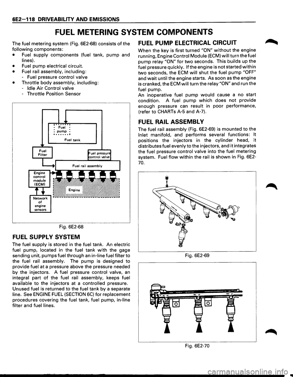
The fuel metering system (Fig. 6E2-68) consists of the
following components:
• Fuel supply components (fuel tank, pump and
lines).
• Fuel
pump electrical circuit.
• Fuel rail assembly, including:
-Fuel pressure control valve
• Throttle
body assembly, including:
-Idle Air Control valve
-Throttle Position Sensor
engine
sensors
• Fuel • :pump : ........
Fuel tank
Fig. 6E2-68
FUEL SUPPL V SYSTEM
The fuel supply is stored in the fuel tank. An electric
fuel
pump, located in the fuel tank with the gage
sending unit, pumps
fuel through an in-line fuel filter to
the
fuel rail assembly. The pump is designed to
provide
fuel at a pressure above the pressure needed
by the injectors. A fuel pressure control valve, an
integral part of the fuel rail assembly, keeps fuel
available
to the injectors at a controlled pressure.
Unused
fuel is returned to the fuel tank by a separate
line. See ENGINE FUEL (SECTION 6C) for replacement
procedures covering the fuel tank, fuel pump, in-line
filter
and fuel lines.
FUEL PUMP ELECTRICAL CIRCUIT
When the key is first turned "ON" without the engine
running, Engine
Control Module (ECM) will turn the fuel
pump relay "ON" for two seconds. This builds up the
fuel pressure quickly. lfthe engine is not started within
two seconds, the ECM will shut the fuel pump "OFF"
and wait until the engine starts. As soon as the engine
is cranked, the
ECM will turn the relay "ON" and run the
fuel pump.
An inoperative
fuel pump would cause a no start
condition. A
fuel pump which does not provide
enough pressure can
result in poor performance,
(refer to CHARTs A-5 and A-7).
FUEL RAIL ASSEMBL V
The fuel rail assembly (Fig. 6E2-69) is mounted to the
Inlet manifold, and performs several functions: It
positions the injectors in the cylinder head, it
distributes fuel evenly to the injectors, and it integrates
the
fuel pressure control valve into the fuel metering
system.
Fuel flow within the rail is shown in Fig. 6E2-
70.
Fig. 6E2-69
Fig. 6E2-70
Page 848 of 1928
6E2-152 DRIVEABILITV AND EMISSIONS
EXHAUST GAS RECIRCULATION (EGR)
VALVE
CHECK
1. Engine operating a normal temperature 60oC
(120°F).
2. Place finger on Exhaust Gas Recirculation (EGR)
valve diaphragm and accelerate engine,
diaphragm
should move.
3. Disconnect vacuum hose from EGR valve.
4. Apply 10" inches of vacuum using a vacuum
pump to valve with finger on diaphragm. It should
move and engine may stall.
5. If valve passes the above test use CHART C-7 A. If
valve fails, replace valve.
EXHAUST GAS RECIRCULATION (EGR)
BACK PRESSURE TRANSDUCER (BPT)
CHECK
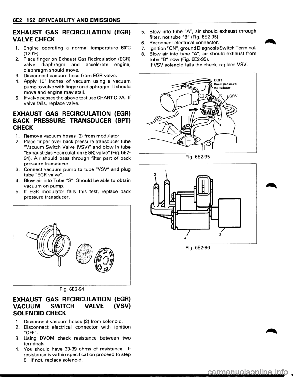
1. Remove vacuum hoses (3) from modulator.
2. Place finger over back pressure transducer tube
"Vacuum Switch Valve (VSV)" and blow in tube
"Exhaust Gas Recirculation (EGR) valve" (Fig. 6E2-
94).
Air should pass through filter part of back
pressure transducer.
3. Connect vacuum pump to tube "VSV" and plug
tube "EGR valve".
4. Blow air into Tube "S". Should be able to obtain
vacuum on pump.
5. If EGR modulator fails this test, replace back
pressure transducer.
Fig. 6E2-94
EXHAUST GAS RECIRCULATION (EGR)
VACUUM SWITCH VALVE (VSV)
SOLENOID
CHECK
1. Disconnect vacuum hoses (2) from solenoid.
2. Disconnect electrical connector with ignition
"OFF".
3. Using DVOM check resistance between two
terminals.
4. You should have 33-39 ohms of resistance. If
resistance is within specification proceed to step
5. If not, replace solenoid.
5. Blow into tube "A", air should exhaust through
filter, not tube "B" (Fig. 6E2-95).
6. Reconnect electrical connector. ~
7. Ignition "ON", ground Diagnosis Switch Terminal.
8. Blow air into tube "A", air should exhaust from
tube "B" now (Fig. 6E2-95).
If VSV solenoid fails the check, replace VSV.
Fig. 6E2-95
4
Fig. 6E2-96
•
Page 893 of 1928
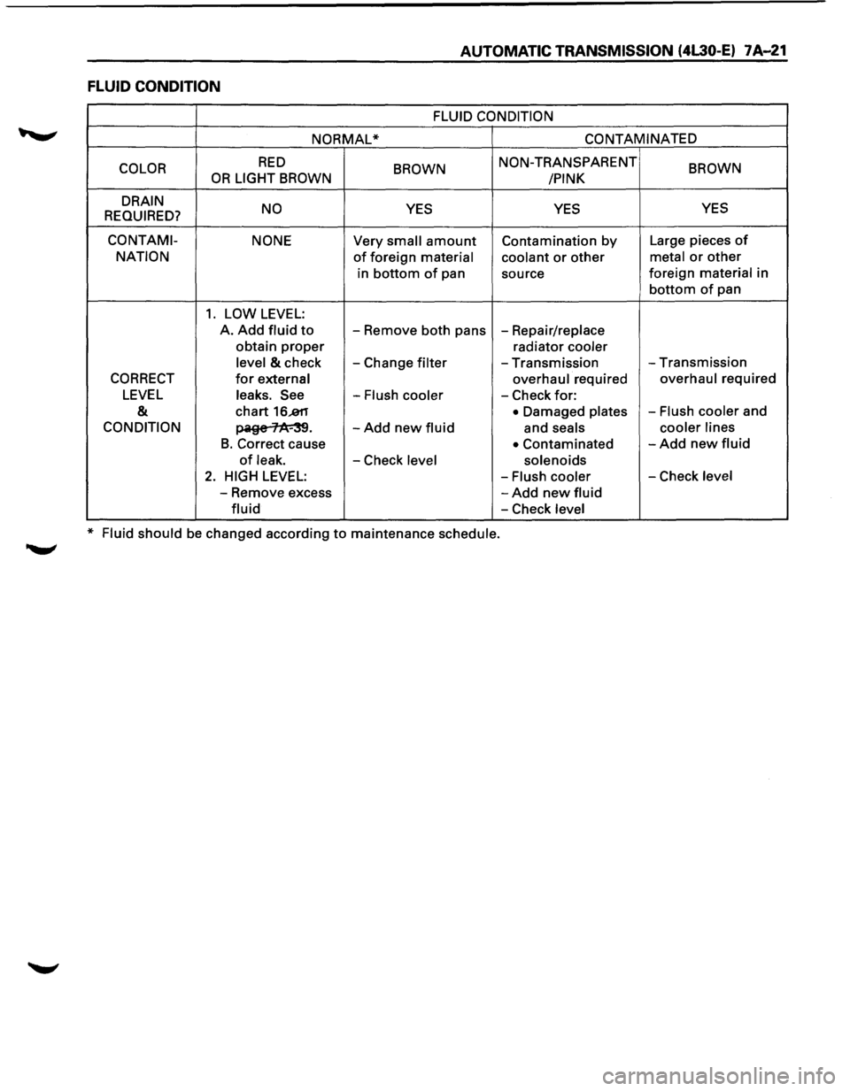
AUTOMATIC TRANSMISSION (4L30-E) 7A-21
FLUID CONDITION
FLUID CONDITION
NORMAL* CONTAMINATED
COLOR
RED BROWN NON-TRANSPARENT BROWN OR LIGHT BROWN
/PINK
DRAIN NO
YES YES YES
REQUIRED?
CO NT AMI- NONE Very small amount Contamination by Large pieces of
NATION of foreign material coolant or other metal or other
in bottom of pan
source foreign material in
bottom of pan
1. LOW LEVEL:
A. Add fluid to -
Remove both pans -Repair/replace
obtain
proper radiator cooler
level
& check -Change filter -Transmission -Transmission
CORRECT for external overhaul required overhaul required
LEVEL leaks. See -Flush cooler -Check for:
& chart 16..811 • Damaged plates -Flush cooler and
CONDITION ~· -Add new fluid and seals cooler
lines
B. Correct cause • Contaminated -Add new fluid
of leak. -Check level solenoids
2. HIGH LEVEL: -Flush cooler -Check level
-Remove excess -Add new fluid
fluid -Check level
* Fluid should be changed according to maintenance schedule.
Page 1045 of 1928
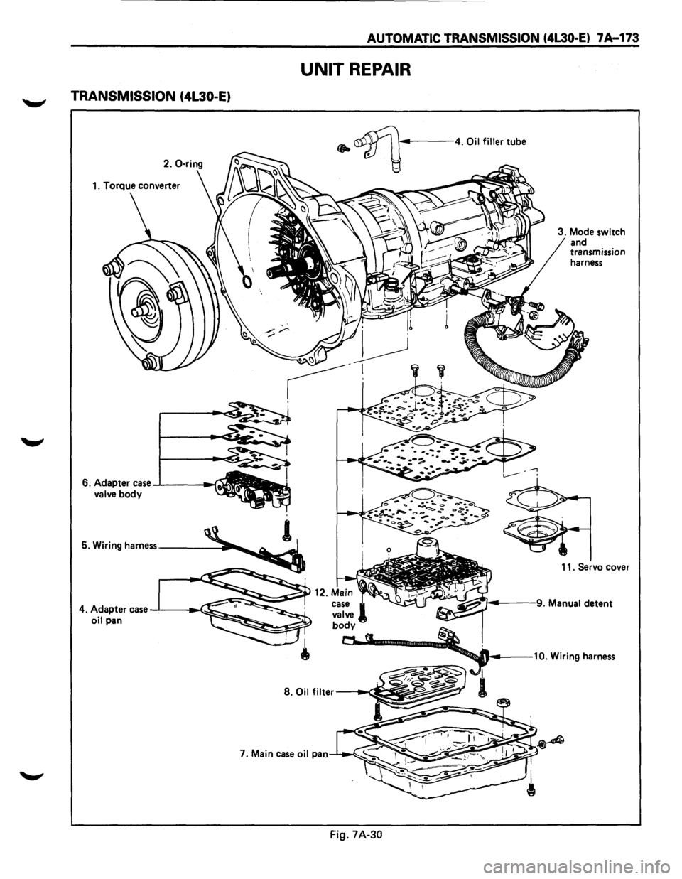
TRANSMISSION (4L30-E)
6. Adapter case -l------f valve body
AUTOMATIC TRANSMISSION (4L30-E) 7 A-173
UNIT REPAIR
• ~-----4. Oil filler tube
3. Mode switch
and
transmission
harness
11. Servo cover
case
valve body
~ §,.::•·• ~~--... ---10. Wiring harness
---1 ..... ~ 1 S.Oilfilter -~
I
Fig. 7A-30
Page 1046 of 1928
7A-174 AUTOMATIC TRANSMISSION (4L30·E)
1•!•1 biSASSEMBLV
During the disassembly and reassembly of the
following components, perform the following:
• Wash each part thoroughly and blow air
through each oil passage and groove to
eliminate blockage.
• Seal rings, roll pins and gaskets should be
replaced
with new parts.
• When assembling the components, apply
DEXRON®-m Automatic Transmission Fluid
(ATF)
to each seal, rotating part and sliding
part.
• Do not dip those parts having a facing, such as
drive plate for clutch or brake, in the cleaner
when washing it with solvent.
Also, always wash
it with new ATF two or
three times after cleaning with solvent.
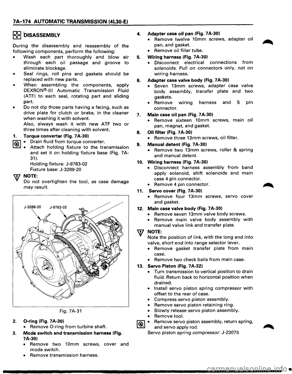
1. Torque converter (Fig. 7A-30)
l"i:\1 • Drain fluid from torque converter.
~ • Attach holding fixture to the transmission
and set it on holding fixture base (Fig. 7A-
31).
Holding fixture: J-8763-02
Fixture base: J-3289-20
w NOTE:
Do
not overtighten the tool, as case damage
may result.
Fig. 7A-31
2. 0-ring (Fig. 7 A-30)
•
Remove 0-ring from turbine shaft.
3. Mode switch and transmission harness (Fig.
7A-30)
•
Remove two 10mm screws, cover and
mode switch.
• Remove transmission harness.
4.
5.
6.
7.
8.
9.
10.
11.
12.
Adapter case oil pan (Fig. 7 A-30)
•
Remove twelve 10mm screws, adapter oil
pan, and gasket.
• Remove oil filler tube.
Wiring harness (Fig. 7 A-30)
•
Disconnect electrical connections from
solenoids. Pull on connectors only, not on
wiring harness.
Adapter case valve body (Fig. 7A-30)
• Seven
13mm screws, adapter case valve
body assembly, transfer plate and two
gaskets.
• Remove wmng harness and 5 pin
connector.
Main case oil pan (Fig. 7 A-30)
•
Remove sixteen 10mm screws, main oil
pan, magnet, and gasket.
Oil filter· (Fig. 7 A-30)
•
Remove three 13mm screws, oil filter.
Manual detent (Fig. 7 A-30)
•
Remove two 13mm screws, roller & spring
and manual detent.
Wiring harness (Fig. 7 A-30)
•
Disconnect harness assembly from band
apply solenoid, shift solenoids and main
case 4 pin connector.
• Remove 4 pin connector.
Servo cover (Fig. 7 A-30)
•
Remove four 13mm screws, servo cover
and
~1asket.
Main case valve body (Fig. 7 A-30)
•
Remove seven 13mm valve body screws.
• Remove main valve body assembly with
manual valve link and transfer plate.
NOTE: Note
thE! position of link, with the long end into
valve, short end into range selector lever.
• Remove gasket transfer plate from main
case.
• Remove two check balls from main case.
13.
Servo Piston (Fig. 7A-32)
• Turn transmission to vertical position to drain
fluid. Return back
to horizontal position when
drained.
• Install servo piston spring compressor with
offset to the rear of case.
• Compress servo piston assembly.
• Remove servo piston retaining ring.
• Slowly release servo piston assembly.
• Remove tool.
1®.1 • Remove servo piston assembly, return spring,
and servo apply rod.
Servo piston spring compressor: J-23075
•