differential ISUZU TROOPER 1995 Workshop Manual
[x] Cancel search | Manufacturer: ISUZU, Model Year: 1995, Model line: TROOPER, Model: ISUZU TROOPER 1995Pages: 1928
Page 14 of 1928
OA-10 GENERAL INFORMATION
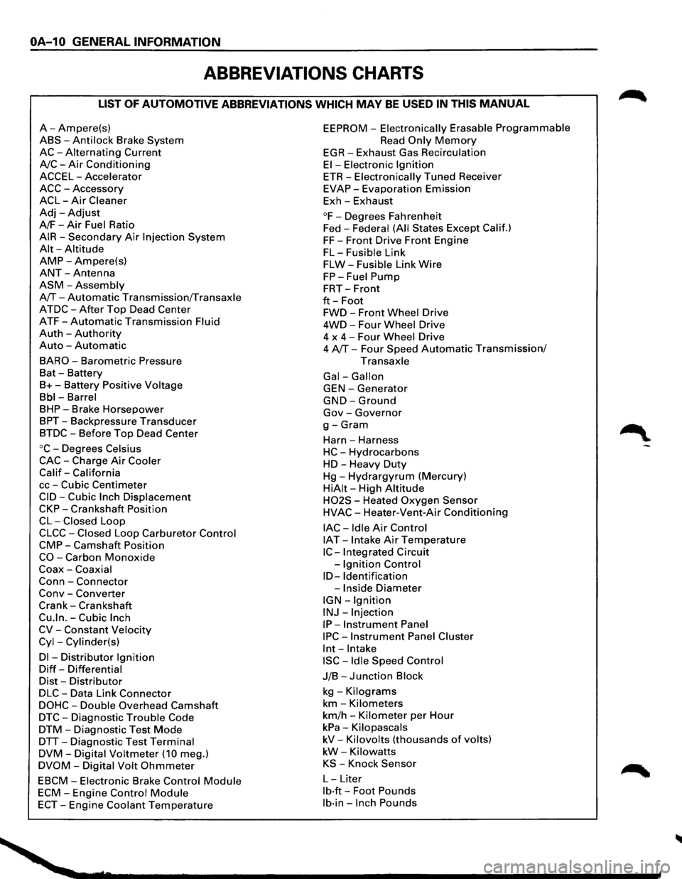
ABBREVIATIONS CHARTS
LIST OF AUTOMOTIVE ABBREVIATIONS WHICH MAY BE USED IN THIS MANUAL
A-Ampere(s)
ABS-Anti lock Brake System
AC-Alternating Current
A/C-Air Conditioning
ACCEL-Accelerator
ACC-Accessory
ACL-Air Cleaner
Adj-Adjust
A/F-Air Fuel Ratio
AIR-Secondary Air Injection System
Alt-Altitude
AMP-Ampere(s)
ANT-Antenna
ASM-Assembly
A/T-Automatic Transmission/Transaxle
ATDC-After Top Dead Center
ATF-Automatic Transmission Fluid
Auth -Authority
Auto -Automatic
BARO-Barometric Pressure
Bat -Battery
B+-Battery Positive Voltage
Bbl-Barrel
BHP-Brake Horsepower
BPT-Backpressure Transducer
BTDC-Before Top Dead Center
oc-Degrees Celsius
CAC-Charge Air Cooler
Calif-California
cc-Cubic Centimeter
CID-Cubic Inch Displacement
CKP-Crankshaft Position
CL-Closed Loop
CLCC-Closed Loop Carburetor Control
CMP-Camshaft Position
CO-Carbon Monoxide
Coax-Coaxial
Conn-Connector
Conv -Converter
Crank-Crankshaft
Cu.ln.-Cubic Inch
CV-Constant Velocity
Cyl-Cylinder(s)
Dl -Distributor Ignition
Diff-Differential
Dist-Distributor
DLC-Data Link Connector
DOHC-Double Overhead Camshaft
DTC-Diagnostic Trouble Code
DTM-Diagnostic Test Mode
DTT-Diagnostic Test Terminal
DVM-Digital Voltmeter (10 meg.)
DVOM-Digital Volt Ohmmeter
EBCM-Electronic Brake Control Module
ECM-Engine Control Module
ECT-Engine Coolant Temperature
EEPROM -Electronically Erasable Programmable
Read Only Memory
EGR-Exhaust Gas Recirculation
El-Electronic Ignition
ETR-Electronically Tuned Receiver
EVAP-Evaporation Emission
Exh-Exhaust
°F-Degrees Fahrenheit
Fed -
Federal (All States Except Calif.)
FF-Front Drive Front Engine
FL-Fusible Link
FLW-Fusible Link Wire
FP-Fuel Pump
FRT-Front
ft-Foot
FWD-Front Wheel Drive
4WD-Four Wheel Drive
4 x
4-Four Wheel Drive
4 A/T-Four Speed Automatic Transmission/
Transaxle
Gal-Gallon
GEN-Generator
GND-Ground
Gov-Governor
g-Gram
Harn -Harness
HC-Hydrocarbons
HD-Heavy Duty
Hg-Hydrargyrum (Mercury)
HiAit-High Altitude
H02S - Heated Oxygen Sensor
HVAC-Heater-Vent-Air Conditioning
lAC-Idle Air Control
IAT -Intake Air Temperature
IC-Integrated Circuit
-
Ignition Control
ID-Identification
-Inside Diameter
IGN-Ignition
INJ-Injection
IP-Instrument Panel
IPC-Instrument Panel Cluster
lnt-Intake
ISC-Idle Speed Control
J/B-Junction Block
kg -Kilograms
km-Kilometers
km/h -Kilometer per Hour
kPa-Kilopascals
kV-Kilovolts (thousands of volts)
kW-Kilowatts
KS -Knock Sensor
L-Liter
lb·ft-Foot Pounds
lb·in-Inch Pounds
Page 24 of 1928
OB-8 MAINTENANCE AND LUBRICATION
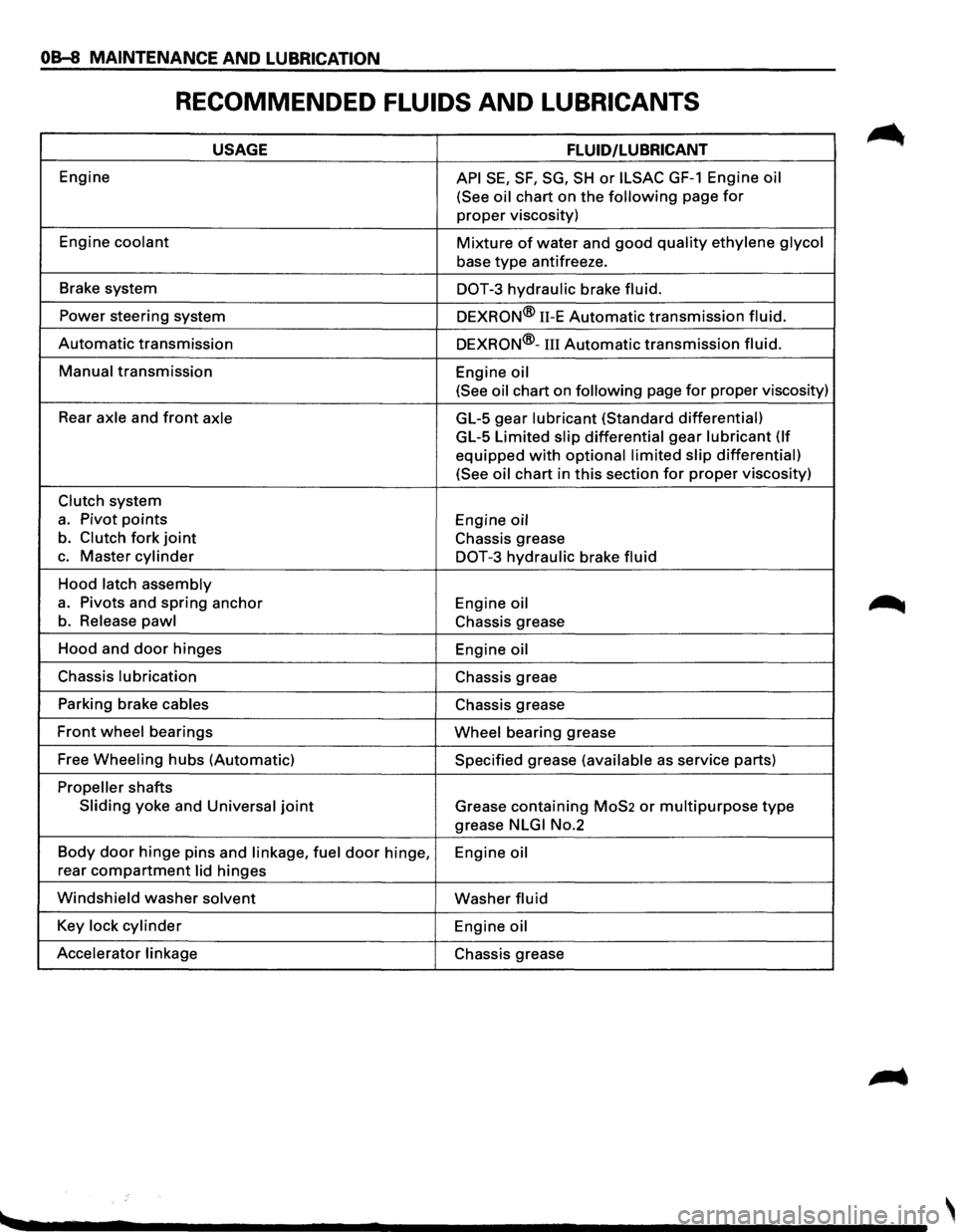
RECOMMENDED FLUIDS AND LUBRICANTS
USAGE FLUID/LUBRICANT
Engine API SE, SF, SG, SH or ILSAC GF-1 Engine oil
(See oil
chart on the following page for
proper viscosity)
Engine
coolant Mixture of water and good quality ethylene glycol
base type antifreeze.
Brake system
DOT-3 hydraulic brake fluid.
Power steering system
DEXRON® 11-E Automatic transmission fluid.
Automatic transmission DEXRON®-III Automatic transmission fluid.
Manual transmission
Engine oil
(See oil
chart on following page for proper viscosity)
Rear
axle and front axle GL-5 gear lubricant (Standard differential)
GL-5 Limited slip differential gear lubricant (If
equipped with optional limited slip differential)
(See oil
chart in this section for proper viscosity)
Clutch system
a. Pivot points Engine oil
b. Clutch fork joint Chassis grease
c. Master cylinder DOT-3 hydraulic brake fluid
Hood latch assembly
a. Pivots and spring anchor
Engine oil
b. Release pawl Chassis grease
Hood and
door hinges
Engine oil
Chassis lubrication Chassis greae
Parking brake
cables Chassis grease
Front wheel bearings Wheel bearing grease
Free
Wheeling hubs (Automatic) Specified grease (available as service parts)
Propeller shafts
Sliding yoke and Universal joint Grease containing MoS2 or multipurpose type
grease NLGI No.2
Body
door hinge pins and linkage, fuel door hinge,
Engine oil
rear compartment lid hinges
Windshield washer solvent Washer fluid
Key lock cylinder Engine oil
Accelerator linkage
Chassis grease
Page 96 of 1928
10-8 COMPRESSOR OVERHAUL
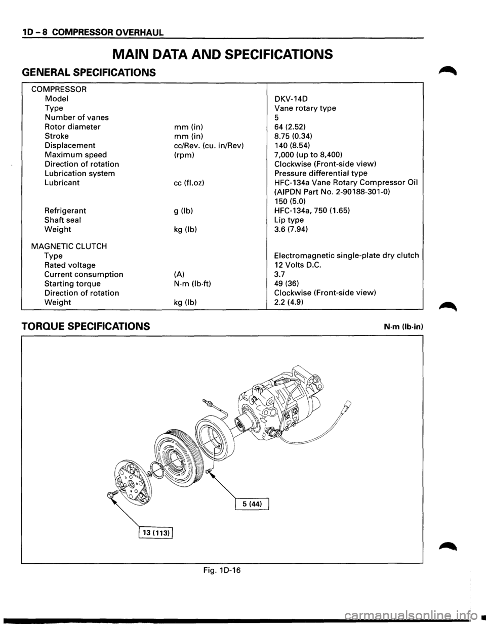
MAIN DATA AND SPECIFICATIONS
GENERAL SPECIFICATIONS
COMPRESSOR
Model
Type
Number of vanes
Rotor
diameter
Stroke
Displacement
Maximum speed
Direction
of rotation
Lubrication system
Lubricant
Refrigerant
Shaft seal
Weight
MAGNETIC CLUTCH
Type
Rated voltage
Current consumption
Starting torque
Direction of rotation
Weight
TORQUE SPECIFICATIONS
mm (in)
mm (in)
cc/Rev. (cu. in/Rev)
(rpm)
cc (fl.oz)
g (lb)
kg (lb)
(A)
N·m (lb·ft)
kg (lb)
Fig. 1D-16 DKV-14D
Vane
rotary type
5 64 (2.52)
8.75
(0.34)
140
(8.54)
7,000 (up to 8,400)
Clockwise
(Front-side view)
Pressure
differential type
HFC-134a Vane Rotary Compressor Oil
(AIPDN
Part No. 2-90188-301-0)
150 (5.0)
HFC-134a, 750 (1.65)
Lip
type
3.6 (7.94)
Electromagnetic single-plate dry clutch
12 Volts D.C.
3.7
49 (36)
Clockwise (Front-side view)
2.2 (4.9)
N·m (lb·in)
•
Page 243 of 1928
REAR AXLE 48-1
SECTION 48
REAR AXLE
\V CAUTION:
When fasteners are removed, always reinstall them at the same location from which they were removed.
If a fastener needs to be replaced, use the correct part number fastener for that application. If the correct
part number fastener is not available, a fastener of equal size and strength (or stronger) may be used.
Fasteners
that are not reused, and those requiring thread locking compound, will be called out. The
correct
torque values must be used when installing fasteners that require torque. If the above conditions
are not followed, parts or system damage could result.
CONTENTS
General Description . . . . . . . . . . . . . . . . . . . . 48-1
Diagnosis of Rear
Axle Noise . .
. . . . . . . . . . 48-3
On-Vehicle Service ..................... 48-4
Axle Housing . .
. . . . . . . . . . . . . . . . . . . . . 48-4
Axle Shaft . .
. . . . . . . . . . . . . . . . . . . . . . . . 48-7
Pinion
Oil Seal . .
. . . . . . . . . . . . . . . . . . . .
48-10
Differential Assembly
. .
. . . . . . . . . . . . . . 48-11 Unit
Repair . . . . . . . . . . . . . . . . . . . . . . . . . . . 48-13
Differential Assembly . .
. . . . . . . . . . . . . .
48-13 Differential Cage Assembly . . . . . . . . . . . . 48-23
Limited
Slip Differential . .
. . . . . . . . . . . . 48-27
Main Data and Specifications . . . . . . . . . . . . 48-33
General Specifications . .
. . . . . . . . . . . . . . 48-33
Torque Specifications
................ 48-34
Special Tools ......................... 48-35
GENERAL DESCRIPTION
The rear axle assembly is of the semi-floating type in
which the vehicle weight is carried on the axle
housing (Fig. 48-1).
The center
line of the pinion gear is below the center
line of the ring gear (hypoid drive).
All parts necessary to transmit power from the
propeller shaft to the rear wheels are enclosed in a
banjo type axle housing.
The 8.7 inch ring gear rear axle uses a conventional
ring and
pinion gear set to transmit the driving force
of the engine to the rear wheels. This gear set transfers
this driving force at a 90 degree angle from the
propeller shaft to the drive shafts. The
axle shafts
are supported at the wheel end of the
shaft by a roller bearing.
The
pinion gear is supported by two tapered roller
bearings. The pinion depth is set by a shim pack
located between the gear end of the pinion and the
roller bearing that is pressed onto the pinion. The
pinion bearing preload is set by crushing a collapsible
spacer between the bearings in the axle housing.
Page 244 of 1928
48-2 REAR AXLE
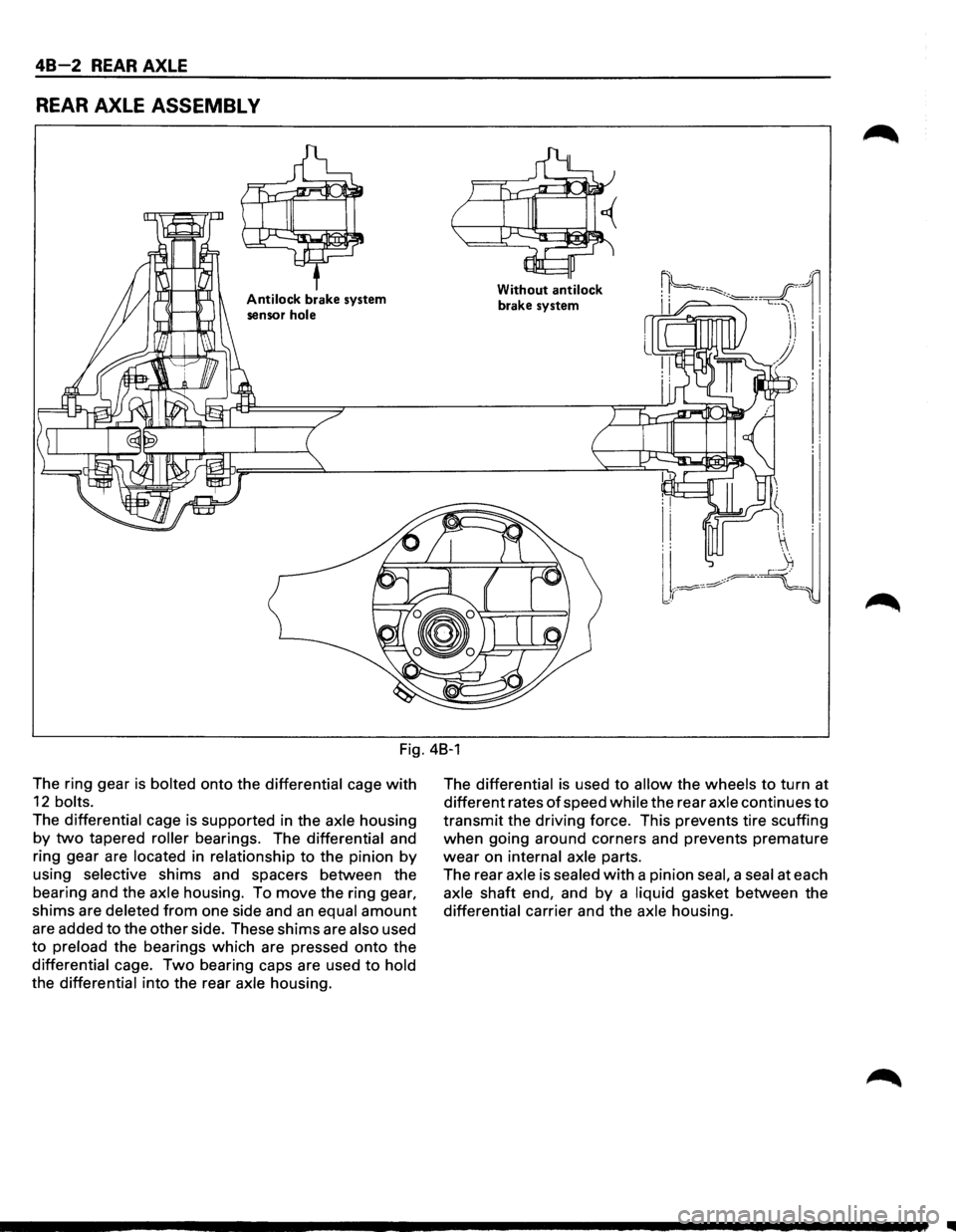
REAR AXLE ASSEMBL V
Antilock brake system
sensor
hole
Without antilock
brake system
Fig. 48-1
The ring gear
is bolted onto the differential cage with
12 bolts.
The differential cage is supported in the axle housing
by two tapered roller bearings. The differential and
ring gear are
located in relationship to the pinion by
using selective shims and spacers between the
bearing and the
axle housing. To move the ring gear,
shims are deleted from one side and an equal amount
are added to the other side. These shims are also used
to preload the bearings which are pressed onto the
differential cage. Two bearing caps are used to hold
the differential into the rear axle housing. The
differential is
used to allow the wheels to turn at
different rates
of speed while the rear axle continues to
transmit the driving force. This prevents tire scuffing
when going around corners and prevents premature
wear on internal axle parts.
The rear
axle is sealed with a pinion seal, a seal at each
axle shaft end, and by a liquid gasket between the
differential carrier and the axle housing.
II
Page 246 of 1928
48-4 REAR AXLE
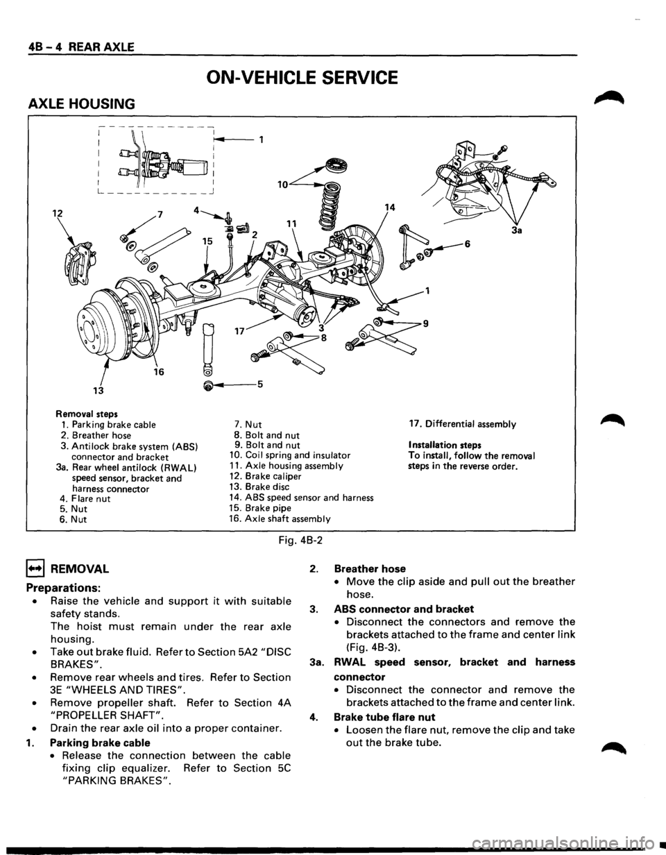
ON-VEHICLE SERVICE
AXLE HOUSING
; ~~:r~4 ,
L ___________ j
12 14
3a
1
• 3
~
~·
13 5
Removal steps
1. Parking brake cable 7. Nut 17.
Differential assembly
2. Breather hose 8.
Bolt and nut 9. Bolt and nut Installation steps
3. Anti lock brake system (ABS)
connector and bracket 10. Coil spring and insulator To install, follow the removal
steps in the reverse order.
3a. Rear wheel antilock (RWAL)
speed sensor, bracket and
harness connector 11.
Axle housing assembly
12. Brake caliper
13. Brake disc
4. Flare
nut 14. ABS speed sensor and harness
5. Nut 15.
Brake pipe
6. Nut 16.
Axle shaft assembly
Fig. 4B-2
1••1 REMOVAL
Preparations:
• Raise the vehicle and support it with suitable
safety stands.
The
hoist must remain under the rear axle
housing.
• Take out brake fluid. Refer to Section 5A2 "DISC
BRAKES".
•
Remove rear wheels and tires. Refer to Section
3E "WHEELS AND TIRES".
•
Remove propeller shaft. Refer to Section 4A
"PROPELLER SHAFT".
•
Drain the rear axle oil into a proper container.
1. Parking brake cable
•
Release the connection between the cable
fixing clip equalizer. Refer to Section 5C
"PARKING BRAKES".
2. Breather hose
• Move the clip aside and pull out the breather
hose.
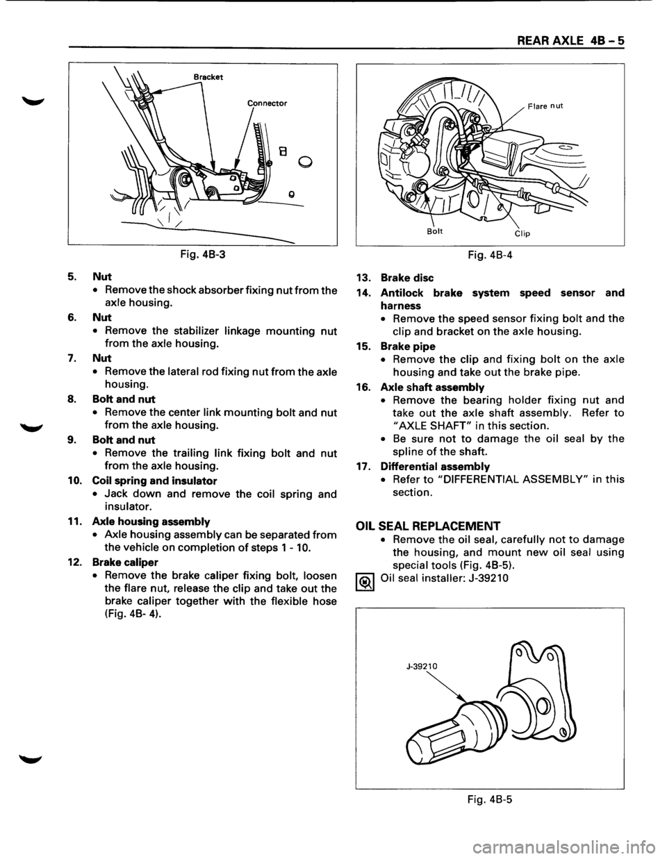
3. ABS connector and bracket
• Disconnect the connectors and remove the
brackets attached to the frame and center link
(Fig. 4B-3).
3a. RWAL speed sensor,
bracket and harness
connector
• Disconnect the connector and remove the
brackets attached to the frame and center link.
4. Brake tube flare nut
• Loosen the flare nut, remove the clip and take
out the brake tube.
•
Page 247 of 1928
5.
6.
7.
8.
........,
9.
10.
11.
12.
B 0
g
Fig. 48-3
Nut
• Remove the shock absorber fixing nut from the
axle housing.
Nut
• Remove the stabilizer linkage mounting nut
from the axle housing.
Nut
• Remove the lateral rod fixing nut from the axle
housing.
Bolt and nut
• Remove the center link mounting bolt and nut
from the axle housing .
Bolt and nut
• Remove the trailing link fixing bolt and nut
from the axle housing.
Coil spring and insulator
• Jack down and remove the coil spring and
insulator.
Axle housing assembly
• Axle
housing assembly can be separated from
the vehicle on completion of steps 1 -10.
Brake caliper
•
Remove the brake caliper fixing bolt, loosen
the
flare nut, release the clip and take out the
brake caliper
together with the flexible hose
(Fig. 48-
4).
REAR AXLE 48 - 5
Bolt Clip
Fig. 48-4
13. Brake disc
14.
Antilock brake system speed sensor and
harness
• Remove the speed sensor fixing bolt and the
clip and bracket on the axle housing.
15. Brake
pipe
• Remove the clip and fixing bolt on the axle
housing and take out the brake pipe.
16.
Axle shaft assembly
• Remove the bearing holder fixing nut and
take
out the axle shaft assembly. Refer to
"AXLE SHAFT" in this section.
• Be sure not to damage the oil seal by the
spline of the shaft.
17. Differential
assembly
• Refer to "DIFFERENTIAL ASSEMBLY" in this
section.
OIL SEAL REPLACEMENT
• Remove the oil seal, carefully not to damage
the housing, and mount new oil seal using
special tools (Fig. 48-5).
1®.1 Oil seal installer: J-39210
Fig. 48-5
Page 248 of 1928
48-6 REAR AXLE
1••1 INSTALLATION
17. Differential assembly
• Refer to "DIFFERENTIAL ASSEMBLY" in this
section.
16.
Axle shaft assembly
• Tighten the bearing holder mounting nut to the
specified torque.
~~~ Torque N·m (lb·ft) 74 (54)
• Be sure not to damage the oil seal by the spline
of the shaft.
15. Brake
pipe
14. Antilock brake system (ABS) speed sensor and
harness
• Refer to Section 5A4 "4-WHEEL ANTI-LOCK
BRAKE SYSTEM (ABS)".
13. Brake disc
12. Brake
caliper
• Refer to Section 5A2 "DISC BRAKES".
11.
Axle housing assembly
10. Coil spring and insulator
9. Bolt and nut
• For the procedures in Items 9-5, refer to Section
3D "REAR SUSPENSION".
8. Bolt and nut
7. Nut
6. Nut
5. Nut
4. Brake tube flare nut
• Refer to Section 5A2 "DISC BRAKES".
3a. Rear Wheel Antilock (RWAL) speed sensor,
bracket and harness connector
• Tighten the speed sensor bolt to the specified
torque.
1~1 Torque N-m (lb·ft) j 24 (18)
3. ABS connector and bracket
2. Breather hose
1. Parking brake cable
• Refer to Section 5C "PARKING BRAKES".
Page 253 of 1928
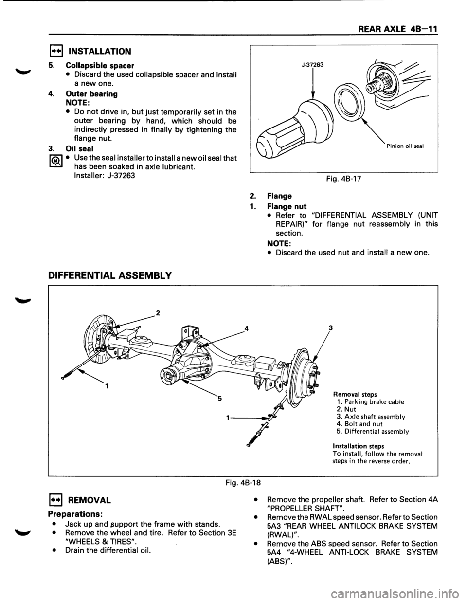
E) INSTALLATION
5. Collapsible spacer
• Discard the used collapsible spacer and install
a new one.
4. Outer bearing
NOTE:
• Do not drive in, but just temporarily set in the
outer bearing
by hand, which should be
indirectly pressed in finally by tightening the
flange nut.
3. Oil seal
1"?.:\1 • Use the seal installer to install a new oil seal that
l.::::'i:il has been soaked in axle lubricant.
Installer:
J-37263
DIFFERENTIAL ASSEMBL V
~ 1
REAR AXLE 48-11
J-37263
Pinion oil seal
Fig. 4B-17
2. Flange
1. Flange nut
• Refer to "DIFFERENTIAL ASSEMBLY (UNIT
REPAIR)" for flange nut reassembly in this
section.
NOTE:
• Discard the used nut and install a new one.
3
/
Removal steps
1. Parking brake cable
2. Nut 3. Axle shaft assembly 4. Bolt and nut 5. Differential assembly
Installation
steps
To install, follow the removal steps in the reverse order.
Fig. 4B-18
E) REMOVAL
Preparations:
• Jack up and .support the frame with stands.
• Remove the wheel and tire. Refer to Section 3E
"WHEELS & TIRES".
•
Drain the differential oil. •
Remove
the propeller shaft. Refer to Section 4A
"PROPELLER SHAFT".
•
Remove the RWAL speed sensor. Refer to Section
5A3
"REAR WHEEL ANTILOCK BRAKE SYSTEM
(RWAL)".
•
Remove the ABS speed sensor. Refer to Section
5A4
"4-WHEEL ANTI-LOCK BRAKE SYSTEM
(ABS)".
Page 254 of 1928
48-12 REAR AXLE
1. Parking brake cable
• Remove the parking brake cable fastening clip
and disconnect the equalizer section. Refer
to
Section SC "PARKING BRAKES".
2. Nut
• Remove the bearing holder fixing nuts.
3. Axle shaft assembly
• Be sure notto damage the oil seal by axle shaft.
4.
Bolt and nut
• Remove differential carrier mounting bolts and
nuts.
5. Differential assembly
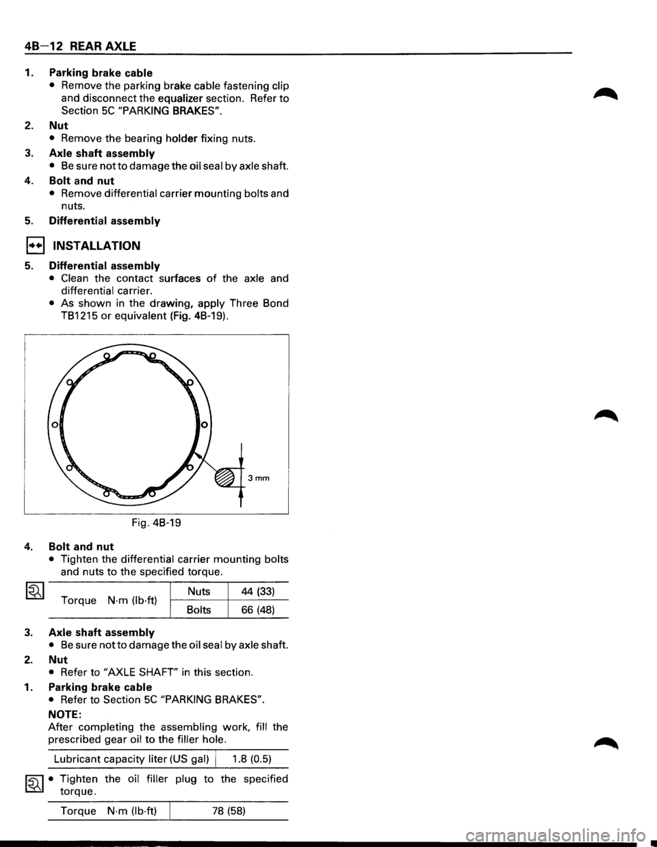
1••1 INSTALLATION
5. Differential assembly
• Clean the contact surfaces of the axle and
differential carrier.
• As shown in the drawing, apply Three Bond
TB1215
or equivalent (Fig. 4B-19).
3mm
Fig. 4B-19
4. Bolt and nut
• Tighten the differential carrier mounting bolts
and nuts
to the specified torque.
Torque
N·m (lb·ft) Bolts Nuts
44
(33)
66 (48)
3. Axle shaft assembly
• Be sure notto damage
the oil seal by axle shaft.
2. Nut
• Refer to "AXLE SHAFT' in this section.
1. Parking brake cable
• Refer to Section 5C "PARKING BRAKES".
NOTE:
After completing the assembling work, fill the
prescribed gear
oil to the filler hole.
~·
Lubricant capacity liter (US gal) j 1.8 (0.5)
Tighten the oil filler plug to the specified
torque.
Torque
N·m (lb·ft) 78 (58)