length ISUZU TROOPER 1995 Owner's Manual
[x] Cancel search | Manufacturer: ISUZU, Model Year: 1995, Model line: TROOPER, Model: ISUZU TROOPER 1995Pages: 1928
Page 1192 of 1928
-·*; ~---
8-2 CHASSIS ELECTRICAL
GENERAL INFORMATION
The chassis electrical system is of 12-volt specifications with a negative ground polarity.
Wire sizes are appropriate
to respective circuits, and classified by color. (The classification of harnesses by
color is shown on the circuit diagram for ease of harness identification.)
The
wire size is determined by load capacity and the length of wire required.
The
vehicle harnesses are: body harness, chassis harness, engine room harness, instrument harness,
transmission harness, engine
ECGI harness, dome light harness, door harness, rear body harness, tailgate
harness,
SRS harness and battery cables.
The harnesses are protected either
by tape or corrugated tube, depending on harness location.
The circuit
for each system consists of the power source, wire, fuse, relay, switch, load parts and ground, all of
which are shown on the circuit diagram.
In this manual, each electrical device is classified by system. For major parts shown on the circuit based on
the circuit diagram
for each system, a summary, diagnosis oftroubles, inspection and removal and installation
procedures are detailed.
NOTES FOR WORKING ON ELECTRICAL ITEMS
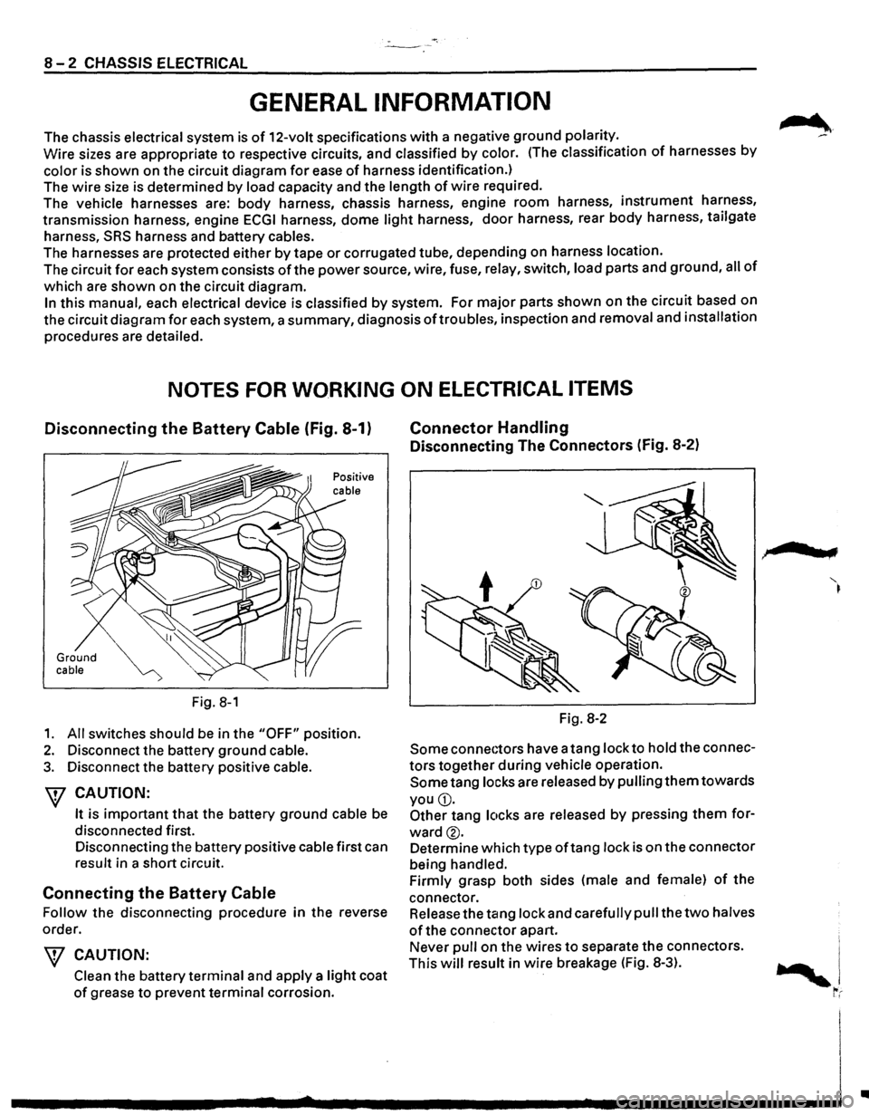
Disconnecting the Battery Cable (Fig. 8-1)
Ground cable
Fig. 8-1
1. All switches should be in the "OFF" position.
2. Disconnect the battery ground cable.
3. Disconnect the battery positive cable.
W CAUTION:
It is important that the battery ground cable be
disconnected first.
Disconnecting the battery positive cable first can
result in a short circuit.
Connecting the Battery Cable
Follow the disconnecting procedure in the reverse
order.
\V CAUTION:
Clean the battery terminal and apply a light coat
of grease to prevent terminal corrosion.
Connector Handling
Disconnecting The Connectors (Fig. 8-2)
Fig. 8-2
Some connectors have a tang lock to hold the connec
tors together during vehicle operation.
Some tang locks are released by pulling them towards
you
G).
Other tang locks are released by pressing them for
ward®.
Determine which type oftang lock is on the connector
being handled.
Firmly grasp both sides (male and female)
of the
connector. Release the tang lock and carefully pull the
two halves
of the connector apart.
Never pull on the wires
to separate the connectors.
This
will result in wire breakage (Fig. 8-3).
.,
..
Page 1196 of 1928
8-6 CHASSIS ELECTRICAL
SPLICING WIRE
1. Open the Harness
If the harness is taped, remove the tape. To avoid wire
insulation damage, use a sewing "seam ripper"
{available from sewing supply stores) to cut open the
harness.
If the harness has a black plastic conduit, simply pull
out the desired wire.
2. Cut the wire
Begin by cutting as little wire off the harness as
possible. You
may need the extra length of wire later
if you decide to cut more wire off to change the
location
of a splice. You may have to adjust splice
locations
to make certain that each splice is at least
1-1/2" {40 mm) away from other splices, harness
branches,
or connectors.
3. Strip the insulation
When replacing a wire, use a wire of the same size as
the original wire. Check the stripped wire for nicks or
cut stands. If the wire is damaged, repeat the proce
dure on a new section of wire. The two stripped wire
ends should be equal in length.
4. Crimp the Wires
Select the proper clip to secure the splice. To deter
mine the proper clip size for the wire being spliced,
follow the directions included with your clips. Select
the correct anvil on the crimper.
{On most crimpers
your choice is limited to either a small or large anvil.)
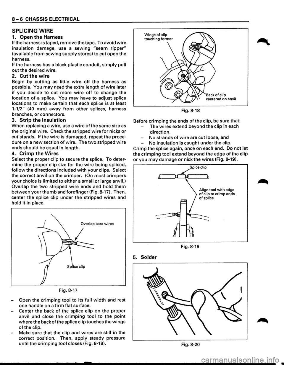
Overlap the two stripped wire ends and hold them
between your thumb and forefinger {Fig. 8-17). Then,
center the splice clip under
the stripped wires and
hold
it in place.
Overlap bare wires
Fig. 8-17
-
Open the crimping tool to its full width and rest
one handle on a
firm flat surface.
- Center
the back of the splice clip on the proper
anvil and close the
crimping tool to the point
where the backofthe splice clip touches the wings
of the clip.
Make sure
that the clip and wires are still in the
correct position. Then,
apply steady pressure
until
the crimping tool closes {Fig. 8-18). Fig.
8-18
Before
crimping the ends ofthe clip, be sure that:
The wires extend beyond
the clip in each
direction.
No strands of wire are cut loose, and
No insulation is caught under
the clip.
Crimp the splice again, once on each end. Do
not let
the crimping tool extend beyond the edge of the clip
or you may damage or nick the wires (Fig. 8-19).
5. Solder
Spice clip
6:~
Fig. 8-19
Align tool with edge of clip to crimp ends of splice
Fig. 8-20
Page 1201 of 1928
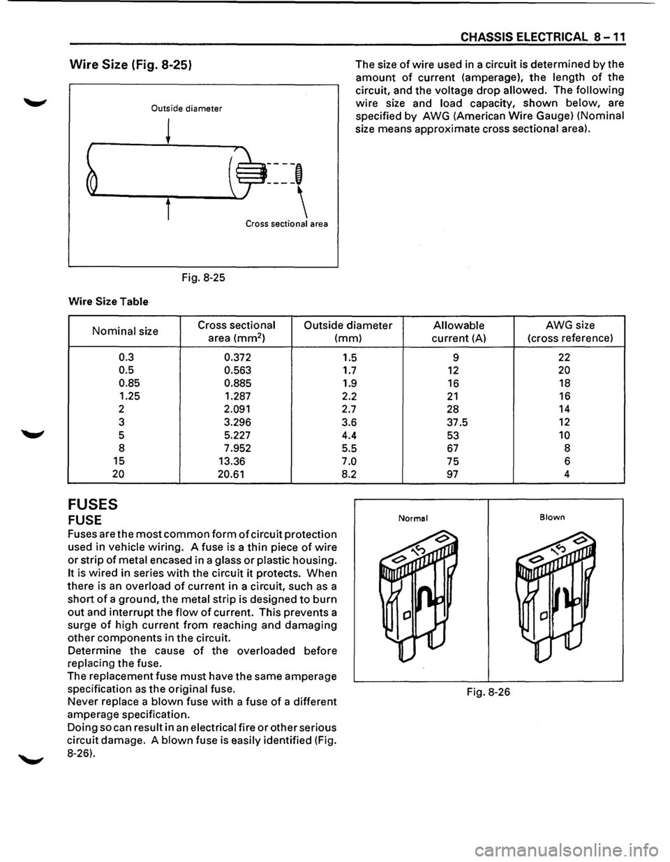
Wire Size (Fig. 8-25)
Outside diameter
Fig. 8-25
Wire Size Table
----,
Cross sectional area
CHASSIS ELECTRICAL 8 -11
The size of wire used in a circuit is determined by the
amount of current (amperage), the length of the
circuit, and the voltage drop allowed. The following
wire size and load capacity, shown below, are
specified
by AWG (American Wire Gauge) (Nominal
size means approximate cross sectional area).
Nominal size Cross sectional
Outside diameter Allowable AWG size
area
(mm2 ) (mm)
0.3
0.5
0.85
1.25
2
3
5 8
15
20
FUSES
FUSE
0.372
0.563
0.885
1.287
2.091
3.296
5.227
7.952
13.36
20.61
Fuses are the most common form of circuit protection
used in vehicle wiring. A fuse is a thin piece of wire
or strip of metal encased in a glass or plastic housing.
It is wired in series with the circuit it protects. When
there is an overload of current in a circuit, such as a
short of a ground, the metal strip is designed to burn
out and interrupt the flow of current. This prevents a
surge
of high current from reaching and damaging
other components in the circuit.
Determine the cause of the overloaded before
replacing the fuse.
The
replacement fuse must have the same amperage
specification as the original fuse.
Never replace a blown fuse with a fuse of a different
amperage specification.
Doing so can result in an electrical fire or other serious
circuit damage. A blown fuse is easily identified (Fig.
8-26). 1.5
1.7
1.9
2.2
2.7
3.6 4.4
5.5
7.0
8.2
current (A) (cross
reference)
9
22
12 20
16 18
21 16
28 14
37.5
12
53 10
67 8
75 6
97 4
Normal Blown
Fig.
8-26
Page 1422 of 1928
8 -232 CHASSIS ELECTRICAL
HEADLIGHT WIPER/WASHER
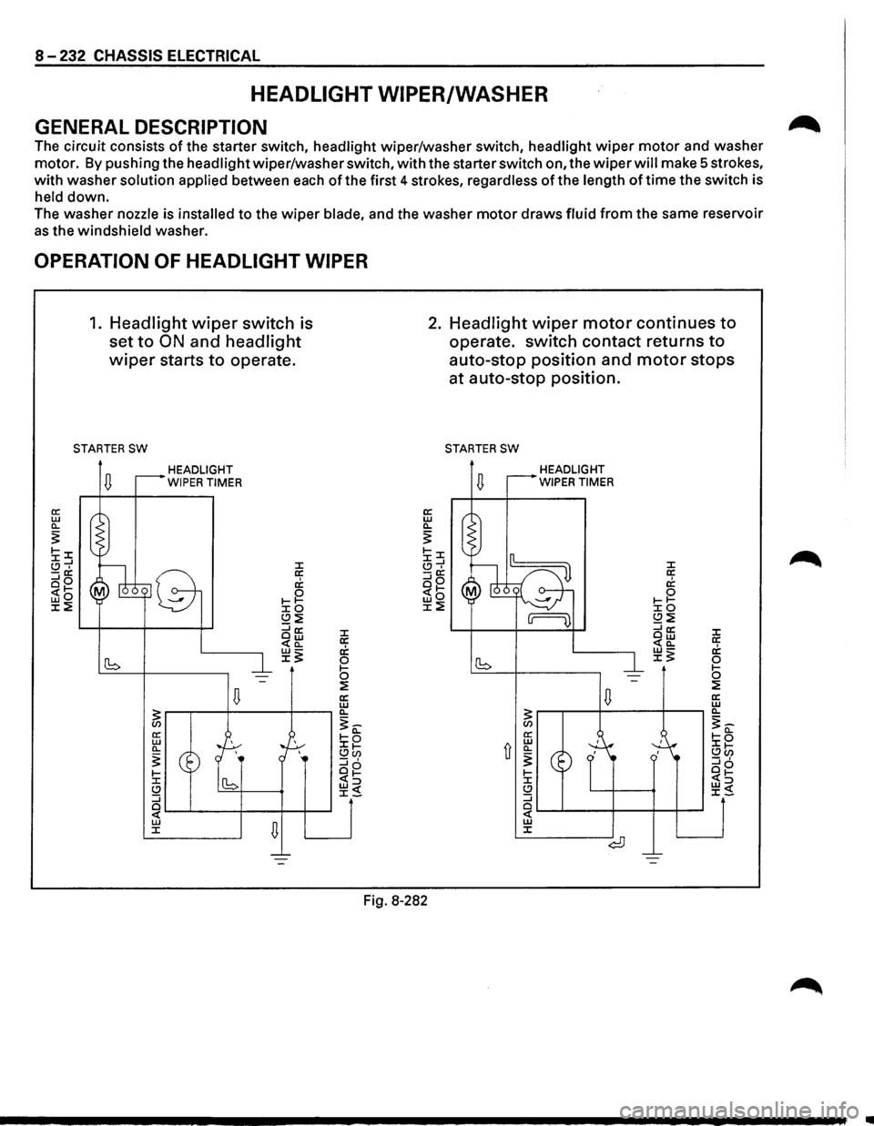
GENERAL DESCRIPTION
The circuit consists of the starter switch, headlight wiper/washer switch, headlight wiper motor and washer
motor. By pushing the headlight wiper/washer switch, with the starter switch on, the wiper will make 5 strokes,
with washer solution applied between each of the first 4 strokes, regardless of the length of time the switch is
held down.
The washer nozzle is installed to the wiper blade, and the washer motor draws fluid from the same reservoir
as the windshield washer.
OPERATION OF HEADLIGHT WIPER
1. Headlight wiper switch is
set
to ON and headlight
wiper starts to operate.
STARTER SW
HEADLIGHT
WIPER TIMER
J: a: c1; 0 1-1-J:O (.!)~ ::::ia: Ow <(a_
~~
Fig. 8-282
2. Headlight wiper motor continues to
operate. switch contact returns to
auto-stop position and motor stops
at auto-stop position.
STARTER SW
HEADLIGHT
WIPER TIMER
..
Page 1641 of 1928
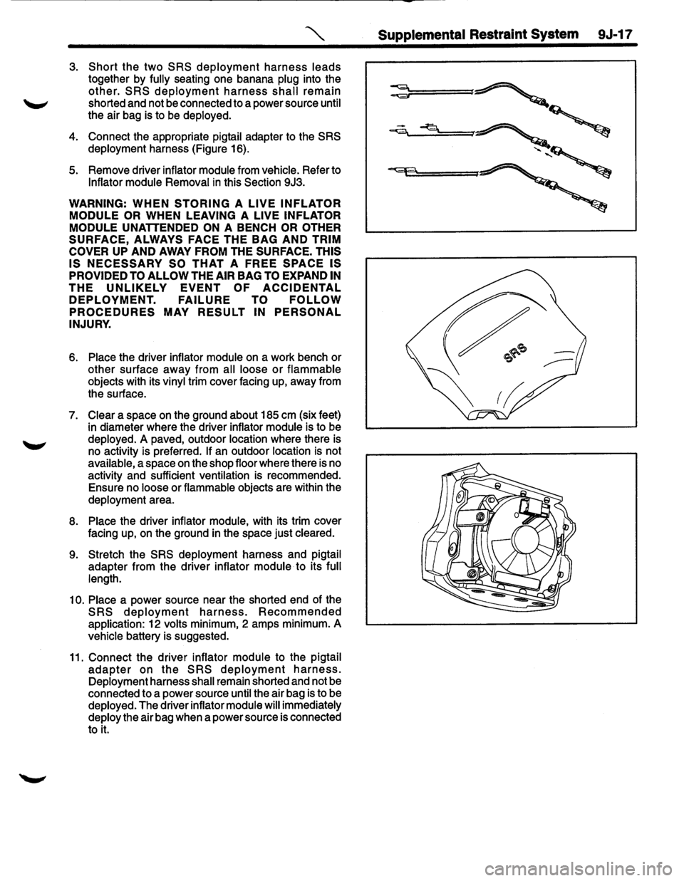
'"""' Supplemental Restraint System 9J-17
3. Short the two SRS deployment harness leads
together by fully seating one banana plug into the
other. SRS deployment harness shall remain
shorted and not be connected to a power source until
the air bag is to
be deployed.
4. Connect the appropriate pigtail adapter to the SRS
deployment harness (Figure 16).
5. Remove driver inflator module from vehicle. Refer to
Inflator module Removal in this Section 9J3.
WARNING: WHEN STORING A LIVE INFLATOR
MODULE OR
WHEN LEAVING A LIVE INFLATOR
MODULE
UNATTENDED ON A BENCH OR OTHER
SURFACE, ALWAYS FACE THE BAG AND TRIM
COVER
UP AND AWAY FROM THE SURFACE. THIS
IS NECESSARY SO THAT A FREE SPACE IS
PROVIDED TO ALLOW THE AIR BAG TO EXPAND IN
THE UNLIKELY EVENT OF ACCIDENTAL
DEPLOYMENT. FAILURE TO FOLLOW
PROCEDURES MAY RESULT IN PERSONAL
INJURY.
6. Place the driver inflator module on a work bench or
other surface away from all loose
or flammable
objects with its vinyl trim cover facing up, away from
the surface.
7. Clear a space on the ground about 185 em (six feet)
in diameter where the driver inflator module is to be
deployed.
A paved, outdoor location where there is
no activity is preferred.
If an outdoor location is not
available, a space
on the shop floor where there is no
activity and sufficient ventilation is recommended.
Ensure no loose or flammable objects are within the
deployment area.
8. Place the driver inflator module, with its trim cover
facing up,
on the ground in the space just cleared.
9. Stretch the SRS deployment harness and pigtail
adapter from the driver inflator module to its full
length.
10. Place a power source near the shorted end of the
SRS deployment harness. Recommended
application: 12 volts minimum, 2 amps minimum. A
vehicle battery is suggested.
11. Connect the driver inflator module to the pigtail
adapter on the SRS deployment harness.
Deployment harness shall remain shorted and not be
connected to a power source until the air bag is to be
deployed. The driver inflator module will immediately
deploy the air bag when a power source is connected
to
it.
Page 1644 of 1928
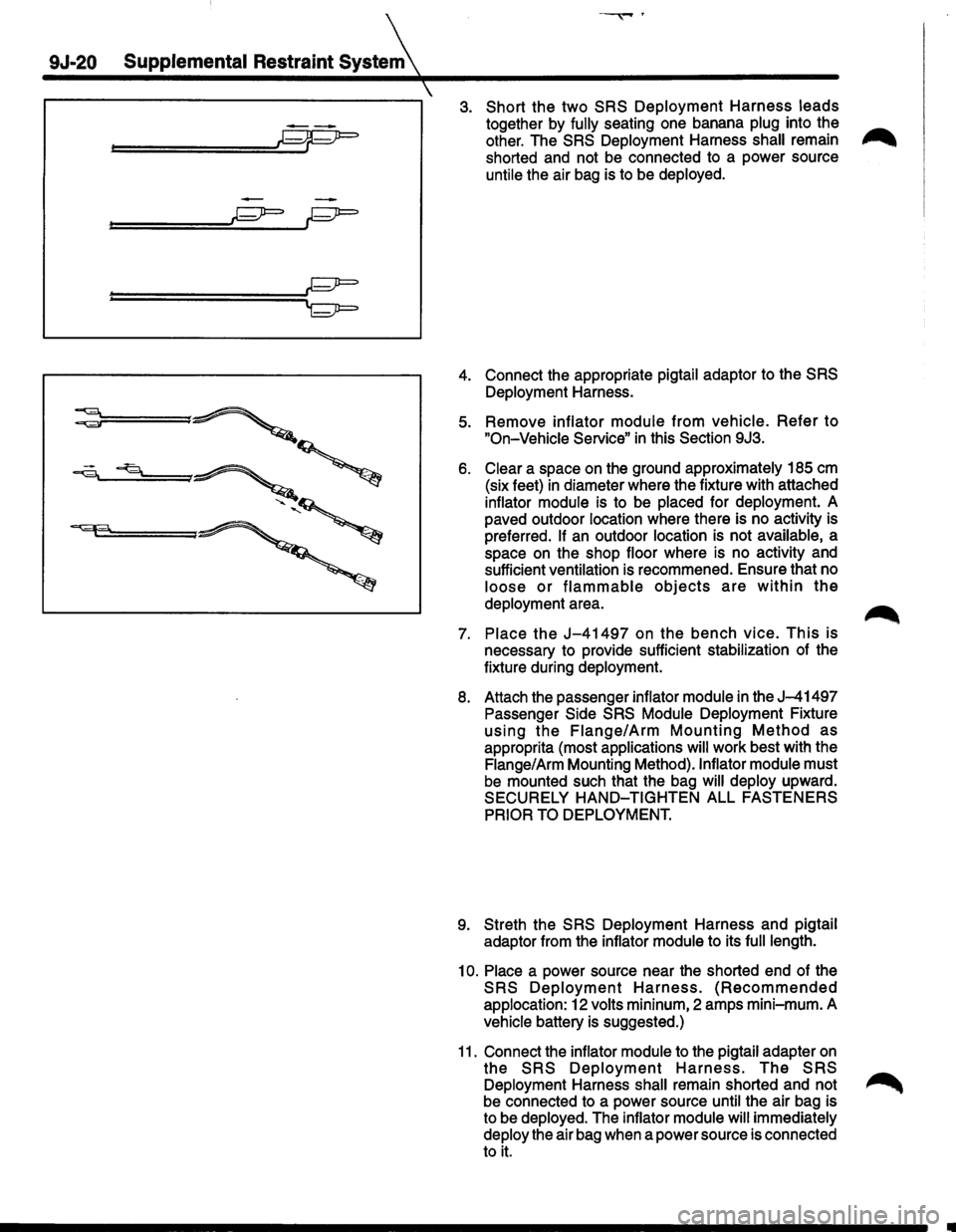
9J-20 Supplemental Restraint SysteA
~----------------------------------~
--
=======C.pp=::::J
============~~ 'r;;;;r=
3. Short the two SRS Deployment Harness leads
together by fully seating one banana plug into the ..-.,.
other. The SRS Deployment Harness shall remain ,..,......
shorted and not be connected to a power source
untile the air bag is to be deployed.
4. Connect the appropriate pigtail adaptor to the SRS
Deployment Harness.
5. Remove inflator module from vehicle. Refer to
"On-Vehicle Service" in this Section 9J3.
6. Clear a space on the ground approximately 185 em
(six feet) in diameter where the fixture with attached
inflator module is to be placed for deployment. A
paved outdoor location where there is no activity is
preferred.
If an outdoor location is not available, a
space on the shop floor where is no activity and
sufficient ventilation is recommened. Ensure that no
loose or flammable objects are within the
deployment area.
7. Place the J-41497 on the bench vice. This is
necessary to provide sufficient stabilization of the
fixture during deployment.
8. Attach the passenger inflator module in the J-41497
Passenger Side SRS Module Deployment Fixture
using the Flange/Arm Mounting Method as
approprita (most applications will work best with the
Flange/Arm Mounting Method).lnflator module must
be mounted such that the bag will deploy upward.
SECURELY
HAND-TIGHTEN ALL FASTENERS
PRIOR TO DEPLOYMENT.
9. Streth the SRS Deployment Harness and pigtail
adaptor from the inflator module to its
full length.
10. Place a power source near the shorted end of the
SRS Deployment Harness. (Recommended
applocation: 12 volts mininum, 2 amps mini-mum. A
vehicle battery is suggested.)
11. Connect the inflator module to the pigtail adapter on
the SRS Deployment Harness. The SRS
Deployment Harness shall remain shorted and not ~
be connected to a power source until the air bag is
to be deployed. The inflator module
will immediately
deploy the air bag when a power source is connected
to it.
Page 1647 of 1928
15. Strip 13 mm(1/2 inch) of insulation from each wire
lead of the connector.
16.
Cut two 900 cm(30 feet) deployment wires from
0.8mm2(18 gauge) or thicker multi-strand wire.
These wires
will be used to fabricate the passenger
deployment harness.
17.
Strip 13 mm {1/2inch)of insulation from both ends of
the wires cut in the previous step.
18.
Short the wires by twisting together one end from
each.
Deployment wires shall remain shorted and
not be connected to a power source
until the air bag
is to be deployed.
WARNING: FAILURE TO FOLLOW
PROCEDURES
IN THE ORDER LISTED COULD RESULT IN
PERSONAL INJURY. NEVER CONNECT
DEPLOYMENT WIRES TO ANY POWER SOURCE
BEFORE CONNECTING DEPLOYMENT WIRES TO
THE INFLATOR MODULE LEADS. DEPLOYMENT
WIRES SHALL REMAIN SHORTED AND NOT BE
CONNECTED TO A POWER SOURCE UNTIL THE
AIR BAG IS DEPLOYED? THE INFLATOR MODULE
WILL IMMEDIATELY DEPLOY THE AIR BAG WHEN
A POWER
SOURCE IS CONNECTED TO IT. WEAR
SAFETY GLASSES THROUGHOUT THIS ENTIRE
DEPLOYMENT AND DISPOSAL PROCEDURE.
19. Twist
together one connector wire lead to one
deployment wire. The connection should be
mechanically secure.
20. Bend twisted connection made in the previous step
flat and wrap tightly with electrical tape to insulate
and secure.
21.
Twist together, bend and tape the remaining
connector wire lead to the remaining deployment
wire.
22. Connect the
deployment harness to the passenger
inflator module jumper, yellow 2-way connector
located behind the 1/P compartment door assembly.
Route deployment harness out the passenger side of
the
vehicle.
WARNING:
DEPLOYMENT WIRES SHALL REMAIN
SHORTED
AND NOT BE CONNECTED TO A POWER
SOURCE UNTIL THE AIR BAG IS TO BE DEPLOYED.
THE INFLATOR MODULE WILL IMMEDIATELY
DEPLOY THE AIR BAG WHEN A POWER SOURCE IS
CONNECTED TO IT. CONNECTING THE
DEPLOYMENT WIRES SHOULD ALWAYS BE THE
FINAL STEP IN THE INFLATOR MODULE
DEPLOYMENT PROCEDURE. FAILURE TO
FOLLOW PROCEDURES IN THE ORDER LISTED
COULD RESULT IN PERSONAL INJURY.
23. Verify that the inside of the vehicle and the area
surrounding the
vehicle are clear of all people and
loose or flammable objects.
24.
Stretch the driver and passenger deployment
harnesses to their full length.
Supplemental Restraint System 9J-23
. Completely cover windshield area and front door
window openings with a drop
cloth, blanket or similar
item. This reduced the possibility of injury due to
possible fragmentation of the vehicle's glass or
interior.
26. Notify
all people in the immediate area that you
intend to
deploy the air bags. The deployment will be
accompanied by a
loud noise which may startle the
uninformed.
27.
Separate the two ends of the driver deployment
harness wires.
WARNING: DEPLOYMENT WIRES SHALL REMAIN
SHORTED
AND NOT BE CONNECTED TO A POWER
SOURCE UNTIL THE AIR BAG IS TO BE DEPLOYED.
THE INFLATOR MODULE WILL IMMEDIATELY
DEPLOY THE AIR BAG WHEN A POWER SOURCE IS
CONNECTED TO IT. CONNECTING THE
DEPLOYMENT WIRES TO THE POWER SOURCE
SHOULD ALWAYS BE THE FINAL STEP IN THE
INFLATOR MODUL,E DEPLOYMENT PROCEDURE.
FAILURE TO FOLLOW PROCEDURES IN THE
ORDER LISTED COULD RESULT IN PERSONAL
INJURY.
NOTE: When the air bag deploys, the rapid gas
expansion will create a loud noise. Notify all people in the
immediate area that you intend to
deploy the air bags.
28. Connect the driver
deployment harness wires to a
power source to immediately deploy the driver
inflator module. Recommended application: 12 volts
minimum, 2 amps minimum. A vehicle battery is
suggested.
29.
Separate the two ends of the passenger deployment
harness wires.
WARNING: DEPLOYMENT WIRES SHALL REMAIN
SHORTED
AND NOT BE CONNECTED TO A POWER
SOURCE UNTIL THE AIR BAG IS TO BE DEPLOYED.
THE INFLATOR MODULE WILL IMMEDIATELY
DEPLOY THE AIR BAG WHEN A POWER SOURCE IS
CONNECTED TO IT. CONNECTING THE
DEPLOYMENT WIRES TO THE POWER SOURCE
SHOULD ALWAYS BE THE FINAL STEP IN THE
INFLATOR MODULE DEPLOYMENT PROCEDURE.
FAILURE TO FOLLOW PROCEDURES IN THE
ORDER LISTED COULD RESULT IN PERSONAL
INJURY.
30.
Connectthe passenger deployment harness wires to
a power source to
immediately deploy the passenger
inflator module. Recommended application: 12 volts
minimum, 2 amps minimum. A vehicle battery is
suggested.
After
an inflator module has been deployed, the
surface of the air bag may contain a powdery
residue. This powder consists primarily of cornstarch
(used to lubricate the bag as it inflates) and
byproducts of the chemical reaction. Sodium
hydroxide dust (similar to lye soap) is produced as a
byproduct of the
deployment reaction. The sodium
Page 1905 of 1928

CONVERSION TABLE A-1
APPENDIX A
CONVERSION TABLES
CONTENTS
Length ........................................................................\
........ A-1
Area ........................................................................\
.......... A-2
Volume ........................................................................\
....... A-3
Mass ........................................................................\
......... A-5
Pressure ........................................................................\
...... A-6
Torque ........................................................................\
....... A-7
Temperature ........................................................................\
.. A-8
LENGTH
MILLIMETERS TO INCHES
INCHES TO MILLIMETERS
mm in. mm in. mm in. mm in. in. mm in. mm
1
0.0394 26 1.0236 51 2.0079
76 2.9921 1/64 0.3969 33/64 13.0969
2 0.0787 27 1.0630
52 2.0472 77 3.0315
1/32 0.7938 17/32 13.4938
3 0.1181
28 1.1024
53 2.0866 78 3.0709
3/64 1.1906 35/64 13.8906
4 0.1575 29 1.1417
54 2.1260
79 3.1102
1/16 1.5875 9/16 14.2875
5 0.1969
30 1.1811
55 2.1654
80 3.1496 5/64 1.9844 37/64 14.6844
6 0.2362
31 1.2205 56 2.2047 81 3.1890 3/32 2.3813 19/32 15.0813
7 0.2756 32 1.2598
57 2.2441
82 3.2283
7/64 2.7781 39/64 15.4781
8 0.3150
33 1.2992
58 2.2835
83 3.2677
1/8 3.1750 5/8 15.8750
9 0.3543
34 1.3386
59 2.3228
84 3.3071 9/64 3.5719 41/64 16.2719 10 0.3937 35 1.3780 60 2.3622
85 3.3465 5/32 3.9688
21/32 16.6688 11 0.4331 36 1.4173 61 2.4016
86 3.3858 11/64 4.3656 43/64 17.0656
12 0.4724
37 1.4567
62 2.4409
87 3.4252
3/16 4.7625 11/16 17.4625
13 0.5118
38 1.4961 63 2.4803
88 3.4646 13/64 5.1594 45/64 17.8594
14 0.5512
39 1.5354 64 2.5197
89 3.5039 7/32 5.5563 23/32 18.2563
15 0.5906 40 1.5748 65 2.5591 90 3.5433 15/64 5.9531 47/64 18.6531
16 0.6299
41 1.6142 66 2.5984 91 3.5827 1/4 6.3500 3/4 19.0500
17
0.6693 42
1.6535
67 2.6378
92 3.6220 17/64 6.7469 49/64 19.4469
18 0.7087 43 1.6929
68 2.6772
93 3.6614 9/32 7.1438 25/32 19.8438 19 0.7480 44 1.7323
69 2.7165
94 3.7008 19/64
7.5406 51/64
20.2406
20 0.7874 45 1.7717
70 2.7559
95 3.7402 5/16 7.9375 13/16 20.6375
21 0.8268 46 1.8110 71 2.7953
96 3.7795 21/64 8.3344 53/64
21.0344
22 0.8661 47
1.8504
72 2.8346
97 3.8189 11/32 8.7313 27/32 21.4313
23 0.9055
48 1.8898 73 2.8740
98 3.8583 23/64 9.1281 55/64 21.8281
24 0.9449
49 1.9291 74 2.9134 99 3.8976 3/8 9.5250 7/8 22.2250
25 0.9843
50 1.9685 75 2.9528
100 3.9370
25/64 9.9219 57/64 22.6219
13/32 10.3188
29/32 23.0188
101 3.9764 111 4.3701 121 4.7638 131 5.1575 27/64 10.7156 59/64 23.4156
102 4.0157 112
4.4094
122 4.8031
132 5.1969
7/16 11.1125 15/16 23.8125
103 4.0551
113 4.4488 123 4.8425 133 5.2362 29/64 11.5094 61/64 24.2094
104 4.0945 114
4.4882 124 4.8819
134 5.2756 15/32
11.9063 31/32 24.6063
105 4.1339 115
4.5276
125 4.9213
135 5.3150
31/64 12.3031 63/64 25.0031
106 4.1732 116
4.5669 126 4.9606 136 5.3543
107 4.2126 117
4.6063 127 5.0000
137 5.3937
108 4.2520 118
4.6457 128 5.0394
138 5.4331 1/2 12.7000
1 25.4000
-109
4.2913
119 4.6850
129 5.0787
139 5.4724
110 4.3307 120 4.7244 130 5.1181 140 5.5118
Page 1906 of 1928
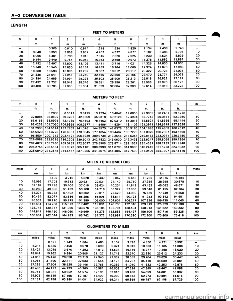
A-2 CONVERSION TABLE
LENGTH
FEET TO METERS
ft. 0 1
2 3 4 5 6 7 8 9 ft.
m
m m m m m m m m m
-0.305 0.610
0.914 1.219 1.524 1.829 2.134 2.438 2.743 -
10 3.048 3.353 3.658 3.962 4.267 4.572 4.877 5.182 5.486 5.791 10
20 6.096 6.401 6.706 7.010 7.315 7.620 7.925 8.230 8.534 8.839 20
30 9.144 9.449 9.754 10.058 10.363 10.668 10.973 11.278
11.582 11.887 30
40 12.192
12.497 12.802 13.106 13.411 13.716 14.021 14.326 14.630 14.935 40
50 15.240 15.545 15.850 16.154 16.459 16.764 17.069 17.374 17.678 17.983 50
60 18.288
18.593 18.898 19.202 19.507 19.812 20.117 20.422 20.726 21.031 60
70
21.336 21.641 21.946 22.250 22.555 22.860 23.165 23.470 23.774 24.079 70
80 24.384 24.689 24.994 25.298 25.603 25.908 26.213 26.518 26.822 27.127 80
90 27.432 27.737 28.042 28.346 28.651 28.956 29.261 29.566 29.870 30.175 90
100 30.480 30.785 31.090 31.394 31.699 32.004 32.309 32.614 32.918
33.223 100
METERS
TO FEET
m 0 1
2
3 4 5
6 7
8 9 m
ft.
ft.
ft. ft. ft. ft. ft. ft. ft. ft.
-3.2808 6.5617 9.8425 13.1234 16.4042
19.6850 22.9659 26.2467 29.5276 -10 32.8084 36.0892 39.3701 42.6509 45.9318 49.2126 52.4934 55.7743 59.0551 62.3360 10
20 65.6168 68.8976 72.1785 75.4593 78.7402 82.0210
85.3018 88.5827 91.8635 95.1444 20
30 98.4252 101.7060 104.9869 108.2677 111.5486 114.8294 118.1102 121.3911 124.6719 127.9528 30 40 131.2336 134.5144 137.7953 141.0761 144.3570 147.6378 150.9186 154.1995 175.4803 160.7612 40 50 164.0420 167.3228 170.6037 173.8845 177.1654 180.4462 183.7270 187.0079 190.2887 193.5696 50 60 196.8504 200.1312 203.4121 206.6929 209.9738 213.2546 216.5354 219.8163 223.0971 226.3780 60
70 229.6588 232.9396 236.2205 239.5013 242.7822 246.0630 249.3438 252.6247 255.9055 259.1864 70
80 262.4672 265.7480 269.0289 272.3097 275.5906 278.8714 282.1522 285.4331 288.7139 291.9948 80 90 295.2756 298.5564 301.8373 305.1181 308.3990 311.6798 314.9606 318.2415 321.5223 324.8032 90 100 328.0840 331.3648 334.6457 337.9265 341.2074 344.4882 347.7690 351.0499 354.3307 357.6116 100
MILES TO
KILOMETERS
miles 0 1
2
3 4 5 6 7 8 9 miles
km
km km km
km km km
km km km
-1.609 3.219 4.828 6.437 8.047 9.656 11.265 12.875 14.484 -10 16.093 17.703 19.312 20.921 22.531 24.140
25.750 27.359
28.968 30.578 10 20 32.187 33.796 35.406 37.015 38.624 40.234 41.843 43.452 45.062 46.671 20 30 48.280
49.890 51.499 53.108 54.718 56.327 57.936 59.546 61.155 62.764 30 40 64.374 65.983 67.592 69.202 70.811 72.420 74.030 75.639 77.249 78.858 40 50 80.467 82.077 83.686 85.295 86.905 88.514 90.123 91.733 93.342 94.951 50 60 96.561 98.170 99.779 101.389 103.000 104.607 106.217 107.826 109.435 111.045 60 70 112.654 114.263 115.873 117.482 119.091 120.700 122.310 123.919 125.529 127.138 70 80 128.748 130.357 131.966 133.576 135.185 136.794 138.404 140.Q13 141.622 143.232 80 90 144.841 146.450 148.060 149.669 151.278 152.888 154.497 156.106 157.716 159.325 90 100 160.934 162.544 164.153 165.762 167.372 168.981 170.590 172.200 173.809 175.418 100
KILOMETERS TO MILES
km 0 1
2 3 4
5 6 7
8
9 km
miles miles
miles miles miles
miles miles miles miles miles
-0.621 1.243 1.864 2.485 3.107 3.728 4.350 4.971 5.592 -10 6.214 6.835 7.456 8.078 8.699 9.321 9.942 10.563 11.185 11.806 10 20 12.427 13.049 13.670 14.292 14.913
15.534 16.156 16.777 17.398 18.020 20 30 18.641 19.262 19.884 20.505 21.127 21.748 22.370 22.990 23.612 24.233 30 40 24.855 25.476 26.098 26.719 27.340 27.962 28.583 29.204 29.826 30.447 40 50 31.065 31.690 32.311 32.933 33.554 34.175 34.797 35.418 36.039 36.661 50 60 37.282 37.904 38.525
39.146 39.768 40.389 41.010 41.632 42.253 42.875 60 70 43.496 44.117 44.739 45.360 45.981 46.603 47.224 47.845 48.467 49.088 70 80 49.711 50.331 50.952 51.574 52.195
52.816 53.438 54.059 54.681 55.302 80 90 55.923 56.545 57.166 57.187 58.409 59.030 59.652 60.273 60.894 61.516 90 100 62.137 62.758 63.380 64.001 64.622 65.244 65.865 66.487 67.108 67.729 100
..