wheel size ISUZU TROOPER 1995 Workshop Manual
[x] Cancel search | Manufacturer: ISUZU, Model Year: 1995, Model line: TROOPER, Model: ISUZU TROOPER 1995Pages: 1928
Page 133 of 1928
FRONT END ALIGNMENT 3A-1
SECTION3A
FRONT END ALIGNMENT
CAUTION:
When fasteners are removed, always reinstall them at the same location from which they were removed. If
a fastener needs to be replaced, use the correct part number fastener for that application. If the correct part
number fastener is not available, a fastener of equal size and strength (or stronger) may be used. Fasteners
that are not reused, and those requiring thread locking compound will be called out. The correcttorque value
must be used when installing fasteners that require it. If the above conditions are not followed, parts or
system damage could result.
CONTENTS
General Description ................................ 3A-1
Camber Adjustment ............................. 3A-4
Definition of Terms .............................. 3A·2 Toe-in Adjustment ............................... 3A-5
On-Vehicle Service ................................. 3A-3 Maximum Steering Angle Adjustment ....... 3A-5
Inspection ......................................... 3A-3 Main Data and Specifications ..................... 3A-6
Trim Height Adjustment ........................ 3A-3 General Specifications .......................... 3A-6
Caster
Adjustment ............................... 3A-3 Torque Specifications ........................... 3A-6
GENERAL DESCRIPTION
"Front End Alignment" refers to the angular
relationship between the front wheels, the front
suspension attaching parts and the ground.
Proper front end alignment must be maintained in
order to insure efficient steering, good directional
stability and to prevent abnormal tire wear.
The
most important factors of front end alignment are
wheel toe-in, wheel camber and axle caster.
Page 139 of 1928
POWER STEERING GEAR AND PUMP 381 -1
SECTION 381
POWER STEERING GEAR AND PUMP
w CAUTION:
When fasteners are removed, always reinstall them at the same location from which they were removed.
If a fastener needs to be replaced, use the correct part number fastener for that application. If the correct
part
number fastener is not available, a fastener of equal size and strength (or stronger) may be used.
Fasteners
that are not reused, and those requiring thread locking compound, will be called out. The correct
torque value must be used when installing fasteners that require it. If the above conditions are not
followed, parts or system damage could result.
CONTENTS
General Description ............................ 3B1- 1
Steering Wheel Free Play Adjustment .... 3B1-5
Power Steering
Gear........................ 3B1-1
Steering Gear ................................ 3B1-6
Hydraulic Pump .............................. 3B1- 1
Power Steering Pump ...................... 3B1-8
Pressure Switch
............................. 3B1-1
Unit Repair ...................................... 3B1- 9
Power Steering System Test
................. 3B1-3
Steering Gear ................................ 3B1-9
On-Vehicle Service ............................. 3B1- 4
Power Steering Pump ...................... 3B1-14
Maintenance
................................. 3B1- 4
Main Data and Specifications ................ 3B1-17
Fluid Level .................................... 3B1- 4 General Specifications ...................... 3B1-17
Bleeding The Power Steering System .... 3B1-4
Torque Specifications ....................... 3B1-17
Bleeding Procedure ......................... 3B1-4 Special Tools.................................... 3B1-18
Flushing The Power Steering System .... 3B1-4
GENERAL DESCRIPTION
The hydraulic power steering system consists of a
pump, an oil reservoir, a steering gear, a pressure
hose and a return hose.
POWER STEERING GEAR
The power steering gear has a recirculating ball
system which acts as a rolling thread between the
worm shaft and the rack piston. When the worm shaft
is
turned right, the rack piston moves up in gear.
Turning the worm shaft left moves the rack piston
down in gear. The rack piston teeth mesh with the
sector, which is part ofthe sector shaft.
Turning the worm shaft turns the sector shaft, which
turns the wheels through the steering linkage.
The control valve in the steering gear directs the
power steering fluid to either side of the rack piston.
The rack
piston converts the hydraulic pressure into
a mechanical force. If the steering system becomes
damaged and loses hydraulic pressure, the vehicle
can be controlled manually (Fig. 381-1).
HYDRAULIC PUMP
The hydraulic pump is vane-type design. The
submerged pump has housing and internal parts that
are inside the reservoir and operate submerged in oil.
There are two bore openings at the rear of the pump
housing. The larger opening contains the cam ring,
pressure
plate, thrust plate, rotor and vane assembly,
and end plate. The smaller opening contains the
pressure
line union, flow control valve and spring
(Fig. 381-2).
PRESSURE SWITCH
When hydraulic pressure reaches 3920 ± 690 kPa
(570 ± 100 psi), the pressure switch closes causing
Engine
Control Module (ECM) to actuate the idle air
control valve to prevent the overload-induced engine
speed down. The switch opens
when hydraulic
pressure drops to 2970 ± 560 kPa (430 ± 80 psi).
Page 157 of 1928
STEERING LINKAGE 383-1
SECTION 383
STEERING LINKAGE
w CAUTION:
• When fasteners are removed, always reinstall them at the same location from which they were removed. If a
fastener needs
to be replaced, use the correct part number fastener for that application. If the correct part
number fastener is not available, a fastener of equal size and strength (or stronger) may be used. Fasteners
that are not reused, and those requiring thread locking compound, will be called out. The correct torque
value must be used when installing fasteners that require it. If the above conditions are not followed, parts or
system damage could result.
CONTENTS
General Description . . . . . . . . . . . . . . . . . . . . 383-1
On-Vehicle Service .................... 383-2
Center Track Rod Assembly . . . . . . . . . . . 383-2
Outer Track Rod Assembly . . . . . . . . . . . . 383-4
Relay Lever . . . . . . . . . . . . . . . . . . . . . . . . . 383-6 Main
Data
and Specifications ............ 383-8
Torque Specifications
................ 383-8
Special Tools .......................... 383-8
GENERAL DESCRIPTION
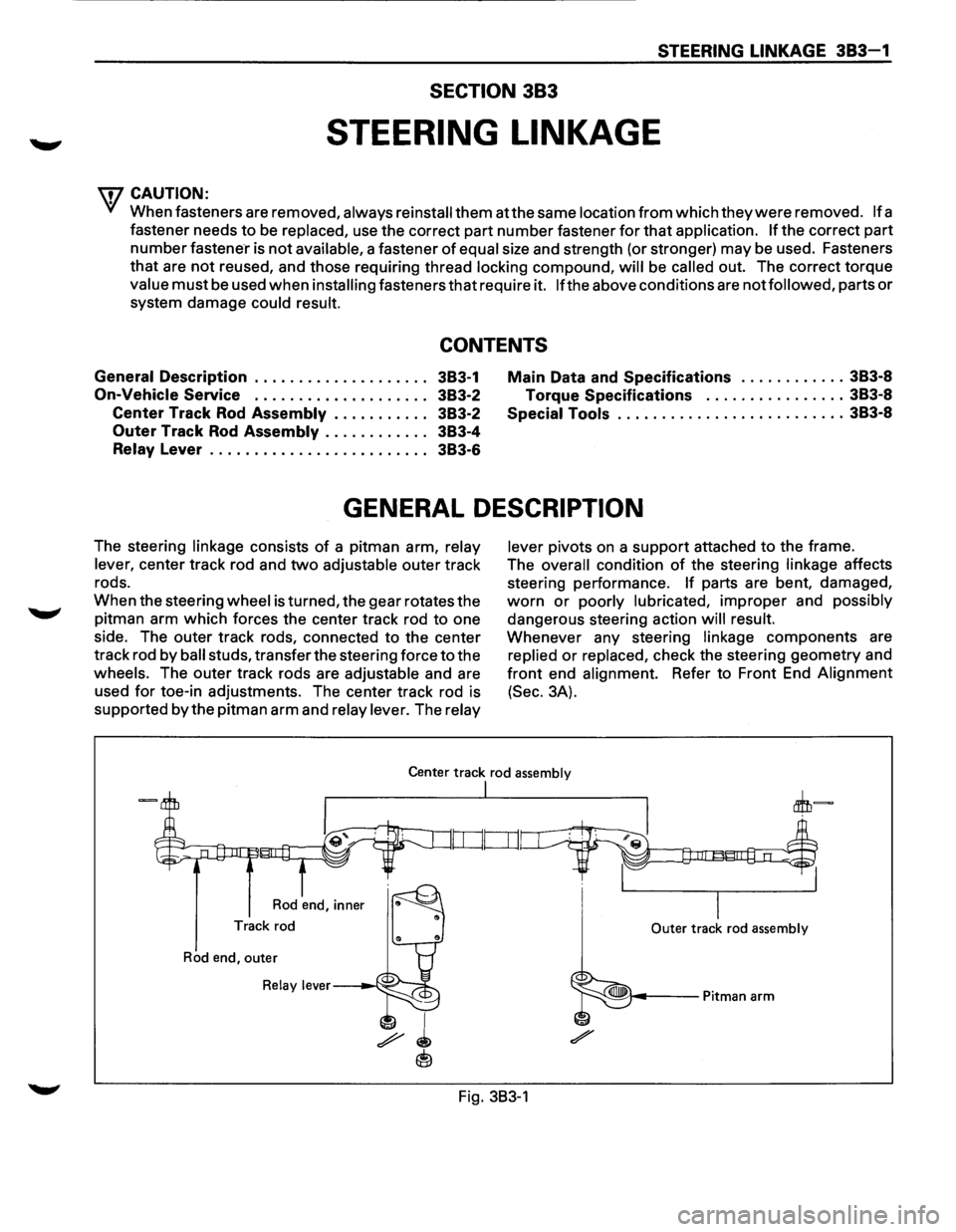
The steering linkage consists of a pitman arm, relay
lever,
center track rod and two adjustable outer track
rods.
When the steering
wheel is turned, the gear rotates the
pitman arm
which forces the center track rod to one
side. The outer track rods, connected to the center
track rod
by ball studs, transfer the steering force to the
wheels. The outer track rods are adjustable and are
used
for toe-in adjustments. The center track rod is
supported
by the pitman arm and relay lever. The relay lever
pivots
on a support attached to the frame.
The
overall condition of the steering linkage affects
steering performance.
If parts are bent, damaged,
worn or poorly lubricated, improper and possibly
dangerous steering action will result.
Whenever any steering linkage components are
replied or replaced, check the steering geometry and
front end alignment. Refer to Front End Alignment
(Sec. 3A).
Center track rod assembly
Rod end, inner
Track rod
Rod end, outer
Relay lever---~·--:;:::jo
I
I Outer track rod assembly
Fig. 383-1
Page 165 of 1928
FRONT SUSPENSION 3C-1
SECTION 3C
FRONT SUSPENSION
'\f CAUTION:
When fasteners are removed, always reinstall them at the same location from which they were removed.
If a fastener needs to be replaced, use the correct part number fastener for that application. If the correct
part
number fastener is not available, a fastener of equal size and strength (or stronger) may be used.
Fasteners
that are not reused, and those requiring thread locking compound, will be called out. The correct
torque value must be used when installing fasteners that require it. If the above conditions are not
followed, parts or system damage could result.
Refer to section 3A in this manual for the wheel alignment procedure.
CONTENTS
General Description .. .. .. .. .. .. .. .. .. .. .. .. .. .. . 3C- 1
On-Vehicle Service .............................. 3C-3
Shock Absorber . . . . . . . . . . . . . . . . . . . . . . . . . . . . . . . 3C-3
Stabilizer Bar . .. .. . .. .. ..
.. . .. .. . .. .. .. . .. .. .. . 3C- 4
Torsion Bar
.................................... 3C-5
Knuckle . .
. . . . . . . . . . . . . . . . . . . . . . . . . . . . . . . . . . . . . . 3C-7
Upper
Control Arm ........................... 3C-10
Lower Control Arm ........................... 3C-13
Upper Ball Joint ............................... 3C- 16
Lower
Ball Joint ............................... 3C-18
Main Data and Specifications.................. 3C-20
General
Specifications . .
. . . . . . . . . . . . . . . . . . . . . 3C-
20
Torque Specifications ........................ 3C-21
Special Tools ..................................... 3C-22
GENERAL DESCRIPTION
The front suspension is designed to allow each wheel
to compensate for changes in the road surface level
without greatly affecting the opposite wheel. Each
wheel is independently connected to the frame by a
steering
knuckle, ball joint assemblies, and upper and
lower control arms. The front wheels are held in
proper relationship to each other by two outer track
rods
which are connected to steering arms on the
knuckles and to a center track rod.
All models have a front suspension system consisting
of control arms, stabilizer bar, shock absorber and a
torsion bar. The front end of the torsion bar is
attached
to the lower control arm. The rear of the
torsion bar is mounted into a height control arm at the
crossmember. Vehicle trim height is controlled by
adjusting this arm.
Shock absorbers are
mounted between the brackets
on the
frame and the lower control arms. The lower
portion of each shock absorber is attached to the
lower control arm by a bolt and nut. The upper portion
of each shock absorber extends through a frame
bracket and is secured with two rubber bushings,
three retainers and a nut.
Ball joint assemblies are bolted to the outer end of the
upper and lower control arm and are attached to the
steering
knuckle by nuts and cotter pins.
The
inner ends of the upper control arm have pressed
in bushings.
Bolts, passing through the bushing,
attach the control arm to the frame. The inner ends of
the lower control arm are attached to the frame by
bolts passing through the bushings, which are
pressed in the frame.
Side
roll of the front suspension is controlled by a
spring steel stabilizer bar. It is mounted in rubber
bushings, which are held to the crossmember by
brackets. The ends of the stabilizer bar are connected
to the lower control arms by links.
Page 201 of 1928
WHEELS AND TIRES 3E-1
SECTION 3E
WHEELS AND TIRES
W CAUTION:
When fasteners are removed, always reinstall them at the same location from which they were removed.
If a fastener needs to be replaced, use the correct part number fastener for that application. If the correct
part
number fastener is not available, a fastener of equal size and strength (or stronger) may be used.
Fasteners
that are not reused, and those requiring thread locking compound, will be called out. The correct
torque value must be used when installing fasteners that require it. If the above conditions are not
followed, parts or system damage could result.
CONTENTS
General Description . . . . . . . . . . . . . . . . . . . . . . . . . . . . . . . 3 E -1 Unit Repair .......................................... 3E-7
Diagnosis ........................................... 3E-2 Tires ............................................... 3E-7
Irregular and Premature Wear ................ 3E-2 Wheels ............................................ 3E-7
Inflation of Tires ................................. 3 E- 3 General Balance Procedure ................... 3E-8
Diagnosis List. . . . . . . . . . . . . . . . . . . . . . . . . . . . . . . . . . . . 3 E- 3 Balancing Wheel and Tire ...................... 3E-8
On-Vehicle Service ................................ 3E-6 Main Data and Specifications .................... 3E-9
Wheels ............................................ 3E-6 General Specifications ......................... 3E-9
Torque Specifications .......................... 3E-9
GENERAL DESCRIPTION
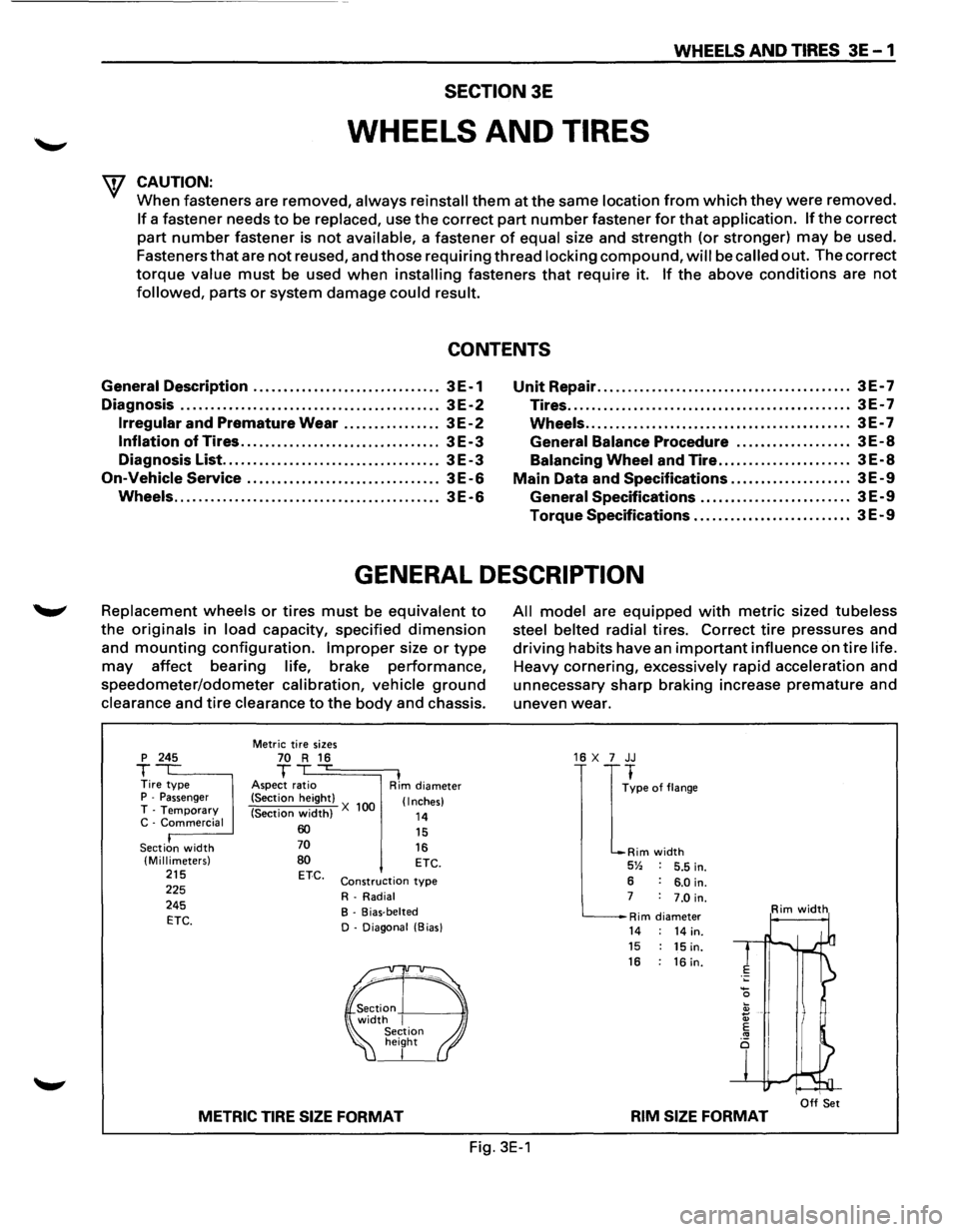
Replacement wheels or tires must be equivalent to
the originals in load capacity, specified dimension
and mounting configuration. Improper size or type
may affect bearing life, brake performance,
speedometer/odometer calibration, vehicle ground
clearance and tire clearance to the body and chassis.
p 245
T Tire type P -Passenger T -Temporary C -Commercial
Section
width (Millimeters) 215 225
245
ETC.
Metric tire sizes 70 R 16 T ,...
Aspect ratio I Rim diameter
(Section height)
(Section
width) X 100 (Inches)
14 60 70
80 ETC.
15
16 ETC.
Construction type
R-Radial
B - Bias-belted
D - Diagonal (Bias)
METRIC TIRE SIZE FORMAT
All model are equipped with metric sized tubeless
steel belted radial
tires. Correct tire pressures and
driving habits have an important influence on tire life.
Heavy cornering, excessively rapid acceleration and
unnecessary sharp braking increase
premature and
uneven wear.
16 X 7 JJ
I
~pe of flange
Rim width 5% 5.5 in.
6 6.0 in. 7 7.0 in.
Rim diameter Rim width
14 14 in. 15 15 in. 16 : 16 in.
I Off Set RIM SIZE FORMAT
Fig. 3E-1
Page 207 of 1928
WHEELS AND TIRES 3E-1
TIRES
REPLACEMENT
UNIT REPAIR
WHEELS
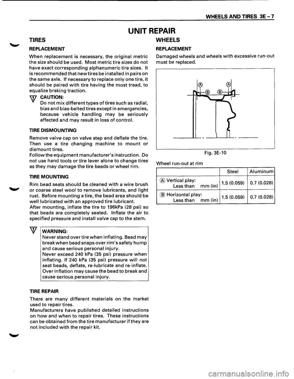
REPLACEMENT
When replacement is necessary, the original metric
the size should be used. Most metric tire sizes do not
have exact corresponding alphanumeric tire sizes. It
is recommended that new tires be installed in pairs on
the same axle. If necessary to replace only one tire, it
should be paired with tire having the most tread, to
equalize braking traction.
w CAUTION:
Do not mix different types of tires such as radial,
bias and bias-belted tires except in emergencies,
because
vehicle handling may be seriously
affected and may result in loss of control.
TIRE DISMOUNTING
Remove valve cap on valve step and deflate the tire.
Then use a
tire changing machine to mount or
dismount tires.
Follow the equipment manufacturer's instruction. Do
not use hand tools or tire lever alone to change tires
as they may damage the tire beads or wheel rim.
TIRE MOUNTING
Rim bead seats should be cleaned with a wire brush
....._., or coarse steel wool to remove lubricants, and light
rust. Before mounting a tire, the bead area should be
well lubricated with an approved tire lubricant.
After mounting, inflate the tire to 196kPa (28 psi) so
that beads are completely seated. Inflate the air to
specified pressure and install valve cap to the stem.
\f WARNING:
Never stand over tire when inflating. Bead may
break when bead snaps over rim's safety hump
and cause serious personal injury.
Never exceed
240 kPa (35 psi) pressure when
inflating. If 240 kPa (35 psi) pressure will not
seat beads, deflate, re-lubricate and re-inflate.
Over
inflation may cause the bead to break and
cause serious
personal injury.
TIRE REPAIR
There are many different materials on the market
used to repair tires.
Manufacturers have published detailed instructions
on how and when to repair tires. These instructions
can be obtained from the tire manufacturer if they are
not included with the repair kit. Damaged
wheels and wheels with excessive run-out
must be replaced.
Fig. 3E-10
Wheel
run-out at rim
Steel Aluminum
@ Vertical play: 1.5 (0.059) 0.7
(0.028) Less than mm(in)
@ Horizontal play: 1.5 (0.059) 0.7
(0.028) Less than mm(in)
Page 208 of 1928
3E-8 WHEELS AND TIRES
GENERAL BALANCE PROCEDURE
Deposits of mud, etc. must be cleaned from the inside
of the rim.
The tire should be inspected
for the following: match
mount paint marks, bent rims, bulges, irregular tire
wear, proper
wheel size and inflation pressure. Then
balance according to the equipment manufacturer's
recommendations.
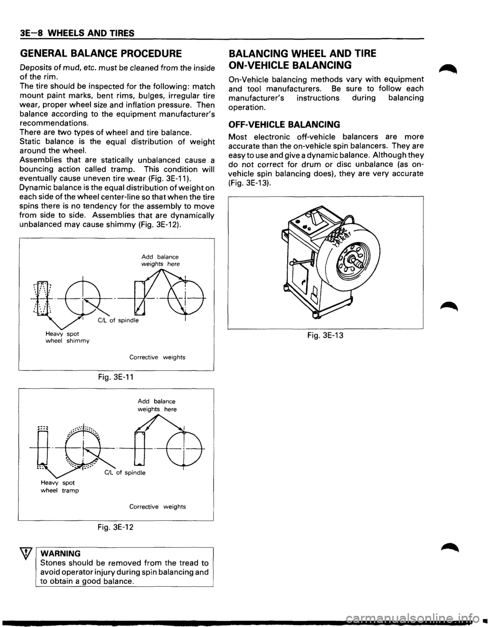
There are
two types of wheel and tire balance.
Static balance is the equal distribution
of weight
around the wheel.
Assemblies
that are statically unbalanced cause a
bouncing action
called tramp. This condition will
eventually
cause uneven tire wear (Fig. 3E-11 ).
Dynamic balance is the equal distribution of weight on
each side
of the wheel center-line so that when the tire
spins there
is no tendency for the assembly to move
from side to side. Assemblies that are dynamically
unbalanced may cause shimmy (Fig. 3E-12).
Heavy spot wheel shimmy
Heavy spot wheel tramp
WARNING
Add balance weights here
Corrective weights
Fig. 3E-11
Add balance
weights here
Corrective weights
Fig. 3E-12
Stones should
be removed from the tread to
avoid operator injury during spin balancing and
to obtain a
good balance.
BALANCING WHEEL AND TIRE
ON-VEHICLE
BALANCING
On-Vehicle balancing methods vary with equipment
and tool manufacturers. Be sure to follow each
manufacturer's instructions during balancing
operation.
OFF-VEHICLE BALANCING
Most electronic off-vehicle balancers are more
accurate than the on-vehicle spin balancers. They are
easy to use and give a dynamic balance. Although
they
do not correct for drum or disc unbalance (as on
vehicle
spin balancing does), they are very accurate
(Fig. 3E-13).
Fig. 3E-13
Page 209 of 1928
WHEELS AND TIRES 3E-9
MAIN DATA AND SPECIFICATIONS
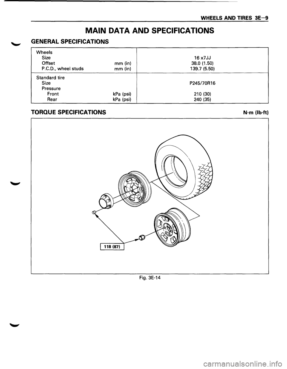
GENERAL SPECIFICATIONS
Wheels
Size
16 x7JJ
Offset mm (in) 38.0 (1.50)
P.C.D.,
wheel studs mm (in) 139.7 (5.50)
Standard tire
Size P245/70R16
Pressure
Front
kPa (psi) 210 (30)
Rear kPa (psi) 240 (35)
TORQUE SPECIFICATIONS
Fig. 3E-14
N·m (lb·ft)
Page 211 of 1928
SUPPLEMENTAL RESTRAINT SYSTEM (SRSl STEERING WHEEL & COLUMN 3F4-1
SECTION 3F4
SUPPLEMENTAL RESTRAINT SYSTEM
STEERING
WHEEL & COLUMN
W CAUTION:
When fasteners are removed, always reinstall them at the same location from which they were removed.
If a fastener needs to be replaced, use the correct part number fastener for that application. If the correct
part
number fastener is not available, a fastener of equal size and strength (or stronger) may be used.
Fasteners
that are not reused, and those requiring thread locking compound, will be called out. The correct
torque value must be used when installing fasteners that require it. If the above conditions are not
followed, parts or system damage could result.
CONTENTS
General Description .......................................... 3F4-1
Lock Cylinder Replacement ......................... 3F4-10
On-Vehicle Service
............................................ 3F4-2 Steering Column Replacement .................... 3F4-13
Special Service Precaution ........................... 3F4-2 Main Data and Specifications .......................... 3F4-17
Inflator Module Replacement ...................... 3F4-3 Torque
Specifications ................................... 3F4-17
Steering Wheel Replacement ...................... 3F4-4 Special Tools ..................................................... 3F4-17
Combination
Switch Replacement ............. 3F4-7
GENERAL DESCRIPTION
W WARNING
TO AVOID DEPLOYMENT WHEN TROUBLE
SHOOTING
THE SRS SYSTEM, DO NOT USE
ELECTRICAL TEST EQUIPMENT, SUCH AS
BATTERY-POWERED OR A/C-POWERED VOLT
METER, OHMMETER, ETC., OR ANY TYPE OF
ELECTRICAL EQUIPMENT OTHER THAN SPE
CIFIED IN THIS MANUAL. DO NOT USE A NON
POWERED
PROBE-TYPE TESTER.
INSTRUCTION IN THIS MANUAL MUST BE
FOLLOWED CAREFULLY, OTHERWISE PER
SONAL INJURY MAY RESULT.
This steering
wheel and column repair section covers
the Supplemental Restraint System (SRS) steering
column. The following repair procedures are specific
to SRS Components. When servicing a vehicle
equipped with Supplemental Restraint System, pay
close attention to all WARNINGS and CAUTIONS.
For detailed explanation about SRS, refer to Section
9J "SUPPLEMENTAL
RESTRAINT SYSTEM (SRS)" of
this manual.
The steering column has three important features in
addition to the steering function:
1. The column is energy absorbing, designed to
compress in a front-end collision to minimize the
possibility of injury to the driver of the vehicle.
2. The ignition switch and lock are mounted con
veniently on the column.
3. With the column mounted lock, the ignition and
steering operation can be
locked to prevent theft
of the vehicle.
The column may be disassembled and reassembled.
To insure the energy absorbing action, it is important
that the specified screws, bolts and nuts be used only
as designated and that they are tightened to the
specified torque.
When the column is removed from the vehicle, a
sharp
blow on the end of steering shaft or shift lever,
leaning
on the column assembly, or dropping the
assembly could shear or loosen the fasteners that
maintain column rigidity.
Page 243 of 1928
REAR AXLE 48-1
SECTION 48
REAR AXLE
\V CAUTION:
When fasteners are removed, always reinstall them at the same location from which they were removed.
If a fastener needs to be replaced, use the correct part number fastener for that application. If the correct
part number fastener is not available, a fastener of equal size and strength (or stronger) may be used.
Fasteners
that are not reused, and those requiring thread locking compound, will be called out. The
correct
torque values must be used when installing fasteners that require torque. If the above conditions
are not followed, parts or system damage could result.
CONTENTS
General Description . . . . . . . . . . . . . . . . . . . . 48-1
Diagnosis of Rear
Axle Noise . .
. . . . . . . . . . 48-3
On-Vehicle Service ..................... 48-4
Axle Housing . .
. . . . . . . . . . . . . . . . . . . . . 48-4
Axle Shaft . .
. . . . . . . . . . . . . . . . . . . . . . . . 48-7
Pinion
Oil Seal . .
. . . . . . . . . . . . . . . . . . . .
48-10
Differential Assembly
. .
. . . . . . . . . . . . . . 48-11 Unit
Repair . . . . . . . . . . . . . . . . . . . . . . . . . . . 48-13
Differential Assembly . .
. . . . . . . . . . . . . .
48-13 Differential Cage Assembly . . . . . . . . . . . . 48-23
Limited
Slip Differential . .
. . . . . . . . . . . . 48-27
Main Data and Specifications . . . . . . . . . . . . 48-33
General Specifications . .
. . . . . . . . . . . . . . 48-33
Torque Specifications
................ 48-34
Special Tools ......................... 48-35
GENERAL DESCRIPTION
The rear axle assembly is of the semi-floating type in
which the vehicle weight is carried on the axle
housing (Fig. 48-1).
The center
line of the pinion gear is below the center
line of the ring gear (hypoid drive).
All parts necessary to transmit power from the
propeller shaft to the rear wheels are enclosed in a
banjo type axle housing.
The 8.7 inch ring gear rear axle uses a conventional
ring and
pinion gear set to transmit the driving force
of the engine to the rear wheels. This gear set transfers
this driving force at a 90 degree angle from the
propeller shaft to the drive shafts. The
axle shafts
are supported at the wheel end of the
shaft by a roller bearing.
The
pinion gear is supported by two tapered roller
bearings. The pinion depth is set by a shim pack
located between the gear end of the pinion and the
roller bearing that is pressed onto the pinion. The
pinion bearing preload is set by crushing a collapsible
spacer between the bearings in the axle housing.