length ISUZU TROOPER 1995 User Guide
[x] Cancel search | Manufacturer: ISUZU, Model Year: 1995, Model line: TROOPER, Model: ISUZU TROOPER 1995Pages: 1928
Page 828 of 1928
6E2-132 DRIVEABILITV AND EMISSIONS
CHART C-20
INDUCTION AIR CONTROL PLATE SYSTEM CHECK
(DOHC ONLY)
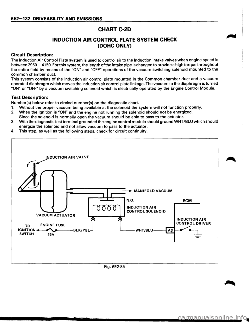
Circuit Description:
The Induction Air Control Plate system is used to control air to the Induction intake valves when engine speed is
between
2950-4150. For this system, the length of the intake pipe is changed to provide a high torque throughout
the entire field by means
of the "ON" and "OFF" operations of the vacuum switching solenoid mounted to the
common chamber duct.
This system consists
of the Induction air control plate mounted in the Common chamber duct and a vacuum
operated diaphragm which moves the
Induction air control plate linkage. The vacuum to the diaphragm is turned
"ON" or "OFF" by a vacuum switching solenoid which is electrically operated by the Engine Control Module.
Test Description:
Number(s) below refer to circled number(s) on the diagnostic chart.
1. Without the proper vacuum being available at the solenoid the system will not function properly.
2. When the ignition is "ON" and the engine not running the solenoid should not be energized.
Since the solenoid is normally open the vacuum should
be able to pass to the actuator.
3. With the diagnostic test terminal grounded the engine control module should ground WHT /BLU which should
energize the solenoid and
not allow vacuum to pass to the actuator.
4. This step, as well as the following steps, check for circuit continuity.
INDUCTION AIR VALVE
fi~
__ __...._ MANIFOLDVACUUM
r-=~=-~ N.O.
VACUUM ACTUATOR
TO IGNITION IIi SWITCH ENGINE
FUSE
fl""'v---BLK/YEL
15A
INDUCTION AIR CONTROL
SOLENOID
'----WHT/BLU---1
Fig. 6E2-85 ECM
INDUCTION AIR CONTROL DRIVER
•
Page 974 of 1928
7A-102 AUTOMATIC TRANSMISSION (4L30-E)
DIAGNOSTIC TROUBLE CODE
(DTC) 34
BAND APPLY SOLENOID SHORT TO GROUND OR OPEN
This DTC flashes the CHECK TRANS indicator and
sets the BACKUP
MODE.
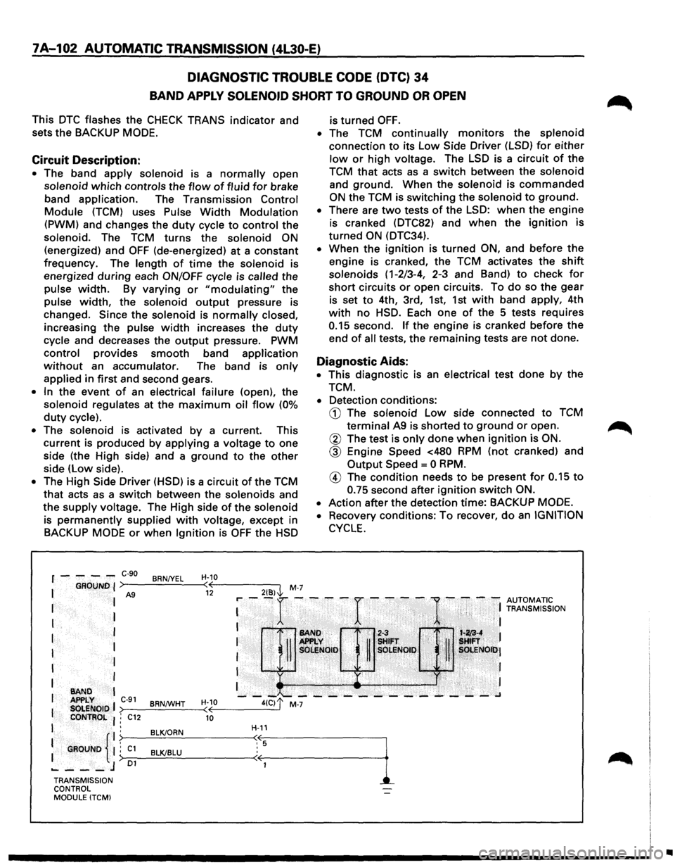
Circuit Description:
• The band apply solenoid is a normally open
solenoid
which controls the flow of fluid for brake
band
application. The Transmission Control
Module (TCM) uses Pulse Width Modulation
(PWM) and changes the duty cycle to control the
solenoid. The
TCM turns the solenoid ON
(energized) and OFF (de-energized) at a constant
frequency. The length
of time the solenoid is
energized
during each ON/OFF cycle is called the
pulse
width. By varying or "modulating" the
pulse
width, the solenoid output pressure is
changed.
Since the solenoid is normally closed,
increasing the pulse width increases the duty
cycle and decreases the output pressure. PWM
control provides smooth band application
without an accumulator. The band is only
applied in first and second gears.
• In the event of an electrical failure (open), the
solenoid regulates at the
maximum oil flow (0%
duty cycle).
• The solenoid is activated by a current. This
current is produced
by applying a voltage to one
side (the High side) and a
ground to the other
side (low side).
• The High Side Driver (HSD) is a circuit of the TCM
that acts as a switch between the solenoids and
the
supply voltage. The High side of the solenoid
is
permanently supplied with voltage, except in
BACKUP
MODE or when Ignition is OFF the HSD
2{8)\l, M-7
r----C-90 BRN/YEL H-10 ( 12
is turned OFF.
• The TCM continually monitors the splenoid
connection
to its low Side Driver (LSD) for either
low or high voltage. The LSD is a circuit of the
TCM that acts as a switch between the solenoid
and
ground. When the solenoid is commanded
ON the TCM is switching the solenoid to ground.
• There are two tests of the LSD: when the engine
is cranked (DTC82) and
when the ignition is
turned ON (DTC34).
• When the ignition is turned ON, and before the
engine is cranked, the TCM activates the shift
solenoids (1-2/3-4, 2-3 and Band) to check for
short circuits or open circuits. To do so the gear
is set
to 4th, 3rd, 1st, 1st with band apply, 4th
with no HSD. Each one of the 5 tests requires
0.15 second. If the engine is cranked before the
end
of all tests, the remaining tests are not done.
Diagnostic Aids:
• This diagnostic is an electrical test done by the
TCM.
• Detection conditions:
CD The solenoid low side connected to TCM
terminal A9 is shorted to ground or open.
@ The test is only done when ignition is ON.
@ Engine Speed <480 RPM (not cranked) and
Output Speed= 0 RPM.
® The condition needs to be present for 0.15 to
0.75 second after ignition switch ON.
•
Action after the detection time: BACKUP MODE.
•
Recovery conditions: To recover, do an IGNITION
CYCLE.
: --r ----r ----
1-
- -: ~Z[;'~,~~ION
I 1'•1 ~~ If ~!FT . i '· !:
I
I
I
1 ·. SOI:!Noto· R sOLI!lQI,~, . ~ , ~. sOt.ENOiti•J
I ,Ji'Ji ·
· I
I •• ) . I
--~~---------~---~ >--------<
I
I I
BAND APPLY C-91 BRNtWHT H-10
I SOLENOID ( CONTROL : C12 10
I .
: GROUND {
. BLK/ORN . ; C1 BLK/BLU :> 01 ..... ---J
H-11
TRANSMISSION
CONTROL
MODULE (TCM)
•
Page 988 of 1928
7A-116 AUTOMATIC TRANSMISSION (4L30-E)
DIAGNOSTIC TROUBLE CODE (DTC) 44
BAND APPLY SOLENOID SHORT TO PLUS
This DTC flashes the CHECK TRANS indicator and
sets the BACKUP
MODE.
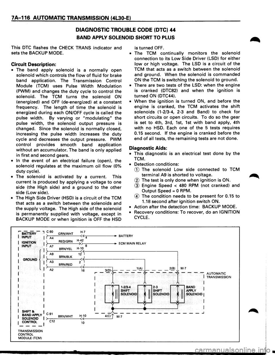
Circuit Description:
• The band apply solenoid is a normally open
solenoid which controls the flow of fluid for brake
band
application. The Transmission Control
Module (TCM) uses Pulse Width Modulation
(PWM) and changes the duty cycle to control the
solenoid. The TCM turns the solenoid ON
(energized) and OFF (de-energized) at a constant
frequency. The
length of time the solenoid is
energized
during each ON/OFF cycle is called the
pulse width. By varying or "modulating" the
pulse width, the solenoid output pressure is
changed.
Since the solenoid is normally closed,
increasing the pulse width increases the duty
cycle and decreases the output pressure. PWM
control provides smooth band application
without an accumulator. The band is only applied
in first and second gears.
• In the event of an electrical failure (open), the
solenoid regulates at the maximum oil flow (0%
duty cycle).
•
The solenoid is activated by a current. This
current is produced by
applying a voltage to one
side (the High side) and a
ground to the other
side (low side).
• The High Side Driver (HSD) is a circuit of the TCM
that acts as a switch between the solenoids and
the
supply voltage. The High side of the solenoid
is permanently supplied with voltage, except in
BACKUP
MODE or when ignition is OFF the HSD
H-7
is turned OFF.
• The TCM continually monitors the solenoid
connection to its Low Side Driver (LSD) for either
low or high voltage. The LSD is a circuit of the
TCM
that acts as a switch between the solenoid
and ground. When the solenoid is commanded
ON the TCM is switching the solenoid to ground.
• There are two tests of the LSD: when the engine
is cranked (DTC82) and
when the ignition is
turned
ON (DTC44).
• When the ignition is turned ON, and before the
engine is cranked, the TCM activates the
shift
solenoids (1-2/3-4, 2-3 and Band) to check for
short circuits or open circuits. To do so the gear
is set
to 4th, 3rd, 1st, 1st with band apply, 4th
with no HSD. Each one of the 5 tests requires
0.15 second. If the engine is cranked before the
end
of all tests, the remaining tests are not done.
Diagnostic Aids:
• This diagnostic is an electrical test done by the
TCM.
• Detection conditions:
CD The solenoid Low side connected to TCM
termin.al A9 is shorted to voltage.
@ The test is only done when ignition is ON.
@ Engine Speed < 480 RPM (not cranked) and
Output
Speed = 0 RPM.
@ The condition needs to be present for 0.15 to
1.18 second after ignition switch ON.
•
Action after the detection time: BACKUP MODE.
•
Recovery conditions: To recover, do an IGNITION
CYCLE.
,... BATTERY-, C-90
I INPUT I? A4 GRN/WHT ·~-----BATTERY
( 4
I IGNITION I ? I INPUT A7 II
I { I? AS I GROUND I ? A3
I
)
I A2
I I
I
I
I I
I I
I
I
I I
I SHIFT& I
I BANDAPPLY C-91 SOLENOID I 1 _:oNTROL _ 1
TRANSMISSION
CONTROL MODULE (TCMI
C12
RED/GRN
BRN/YEL
BRN/BLK
BRN/RED
BRN/WHT
H-42 •--::------ECM MAIN RELAY )) 8 H-10
«--------3-(D--,I'l----- --'~L -,,,l M-7
( 12
2:j
16 r-- -r ----r ----
1-- --
AUTOMATIC I
I TRANSMISSION
: H::Q]:;& : I OLE SOlENOID I
I I
I I
1-213-4 2-:
-II
SHIFT
II
s SOLE NOlO s
-"--------_______ .J
H-10 ( 10
•
Page 1035 of 1928
AUTOMATIC TRANSMISSION (4L30-E) 7A-163
I••IINSTALLALTION
To install, follow the removal steps in the reverse
order,
noting the following points;
22. Transmission assembly
•
Slowly raise transmission jack until front of
the transmission is aligned with rear of the
engine.
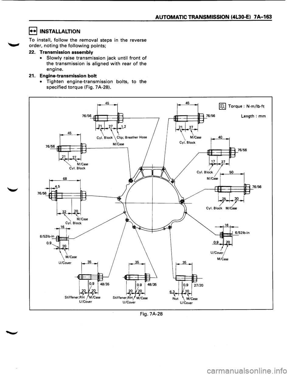
21. Engine-transmission
bolt
•
Tighten engine-transmission bolts, to the
specified
torque (Fig. 7A-28).
76/56
21 27 1.2
Cy~Bioc~21ip; Breather Hose
M/Case
68
Stiffener;R H M/Case U/Cover
Fig. 7A-28
45
35 ~ Torque : N·m/lb·ft
Length: mm
40
,---iEJE~I:=ll=1_::76/56
Cyl Blo~ r--1
M/Case J
1
-------e9E~~=~a.l_76/56
~ Cyl. Block M/Case
M/Case
Page 1098 of 1928
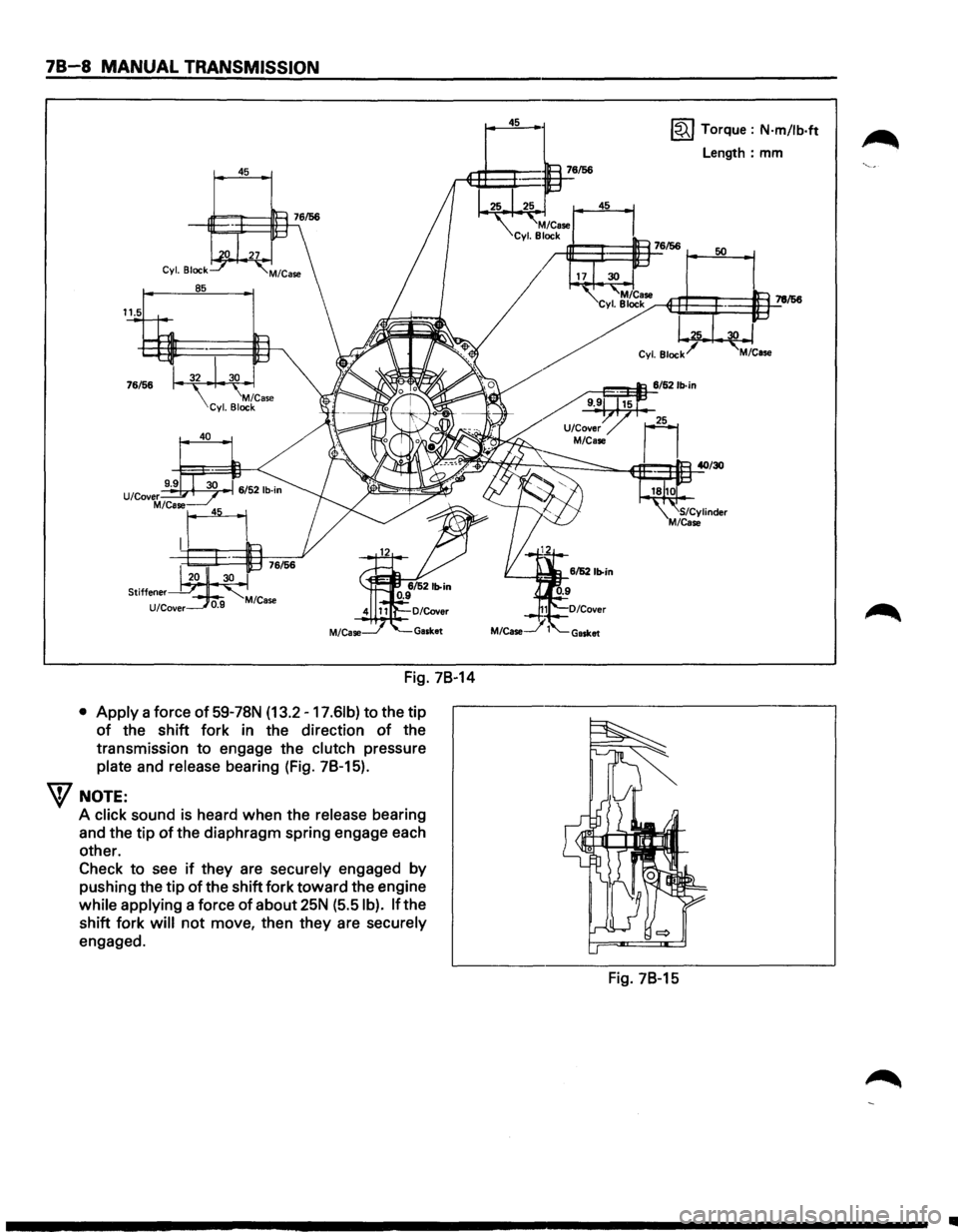
78-8 MANUAL TRANSMISSION
45
Fig. 78-14
• Apply a force of 59-78N (13.2 -17.61b) to the tip
of the shift fork in the direction of the
transmission
to engage the clutch pressure
plate and release bearing (Fig. 78-15).
W NOTE:
A click sound is heard when the release bearing
and the tip
of the diaphragm spring engage each
other.
Check
to see if they are securely engaged by
pushing the tip of the shift fork toward the engine
while applying a force
of about 25N (5.5 I b). If the
shift fork
will not move, then they are securely
engaged.
45 ~ Torque : N·m/lb·ft
Length: mm
Fig. 78-15
..
Page 1110 of 1928
78-20 MANUAL TRANSMISSION
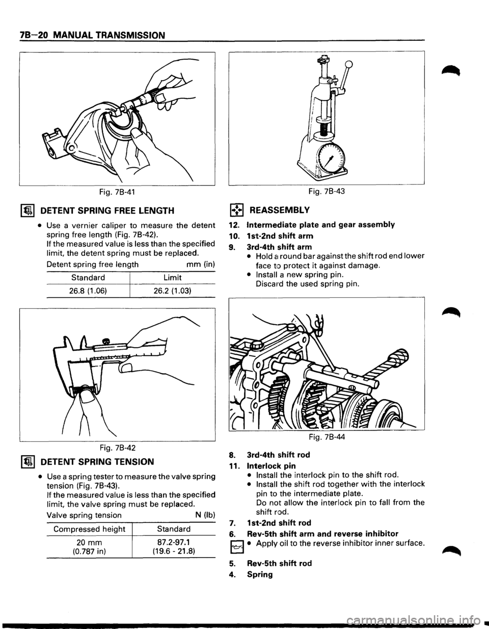
Fig. 78-41
~ DETENT SPRING FREE LENGTH
• Use a vernier caliper to measure the detent
spring free length (Fig. 78-42).
If the measured value is less than the specified
limit, the
detent spring must be replaced.
Detent spring free length
mm (in)
Standard Limit
26.8 (1.06) 26.2 (1.03)
Fig. 78-42
~ DETENT SPRING TENSION
• Use a spring tester to measure the valve spring
tension (Fig. 78-43).
If the measured value is less than the specified
limit, the valve spring must be replaced.
Valve spring tension
N (lb)
Compressed height Standard
20 mm 87.2-97.1
(0.787 in) (19.6-21.8) Fig.
78-43
l•!•l REASSEMBLY
12. Intermediate plate and gear assembly
10.
1st-2nd shift arm
9. 3rd-4th shift arm
• Hold Cl round bar against the shift rod end lower
face to protect it against damage.
• Install a new spring pin.
Discard the used spring pin.
Fig. 78-44
8. 3rd-4th shift rod
11. Interlock pin
• Install the interlock pin to the shift rod.
• Install the shift rod together with the interlock
pin
to the intermediate plate.
Do
not allow the interlock pin to fall from the
shift
rod.
7. 1st-2nd shift rod
6. Rev-5th shift arm and reverse inhibitor
EJ • Apply oil to the reverse inhibitor inner surface.
5. Rev-5th shift rod
4. Spring
..
Page 1163 of 1928
46/34
30
T/F Case
T/M case
+/F Case
T/M Case
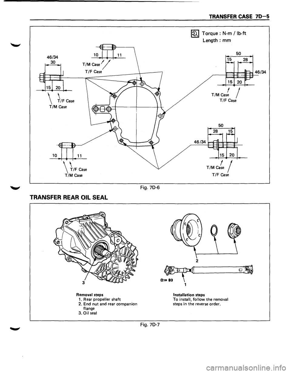
TRANSFER REAR OIL SEAL
Removal steps
1. Rear propeller shaft
2. End nut and rear companion
flange
3.
Oil seal
Fig. 70-6
Fig. 70-7
1
TRANSFER CASE 70-5
1~1 Torque: N·m /lb·ft
Length: mm
50
15 28
15 20
T/M Cas! I
T/F Case
50
28 15
T/M Ca~e I
T/F case
2
0 ,""o
Installation steps
To install, follow the removal
steps in the reverse order.
Page 1180 of 1928
7D-22 TRANSFER CASE
Inspect the components for the following:
• Teeth for wear, scuffs, nicks, burrs or breaks.
• Keys and springs for wear, cracks or distortion,
replace
if these conditions are present.
• If scuffed, 'nicked or burred conditions cannot be
corrected with a soft stone or crocus cloth,
replace the component.
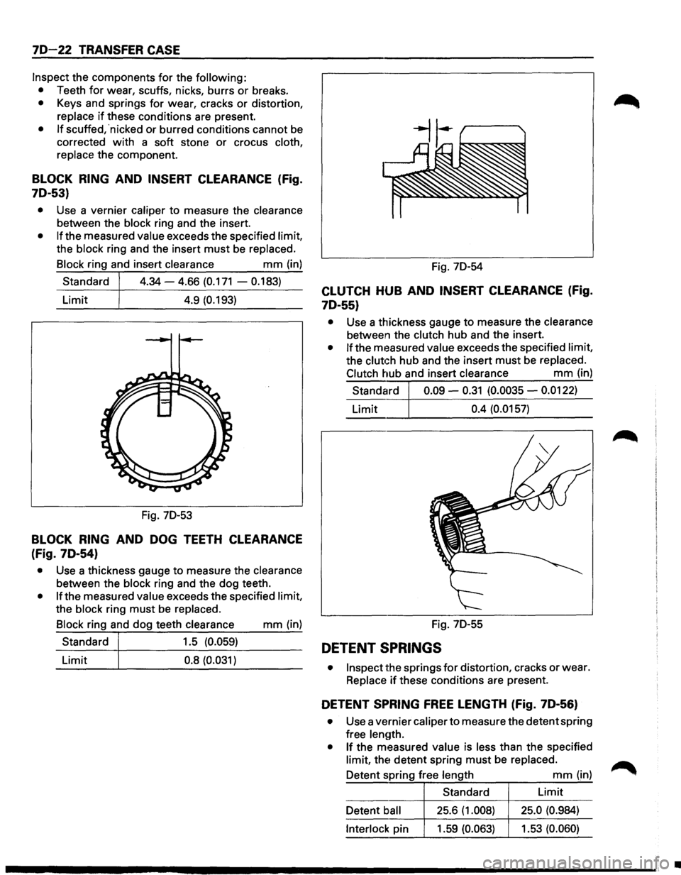
BLOCK RING AND INSERT CLEARANCE (Fig.
7D-53)
• Use a vernier caliper to measure the clearance
between the block ring and the insert.
• If the measured value exceeds the specified limit,
the block ring and the insert
must be replaced.
Block ring and insert clearance
mm (in)
Standard
4.34-4.66 (0.171 - 0.183)
Limit 4.9 (0.193)
Fig. 7D-53
BLOCK RING AND DOG TEETH CLEARANCE
(Fig. 7D-54)
• Use a thickness gauge to measure the clearance
between the block ring and the dog teeth.
• If the measured value exceeds the specified limit,
the block ring
must be replaced. Fig.
7D-54
CLUTCH HUB AND INSERT CLEARANCE (Fig.
7D-55)
• Use a thickness gauge to measure the clearance
between the clutch hub and the insert.
• If the measured value exceeds the specified limit,
the
clutch hub and the insert must be replaced.
Clutch hub and insert clearance
mm (in)
Standard 0.09 -
0.31 (0.0035 -0.0122)
Limit 0.4 (0.0157)
Block ring and dog teeth clearance
mm (in) Fig. 7D-55 ------~~--~------------------~ Standard 1.5 (0.059)
Limit 0.8
(0.031) DETENT SPRINGS
• Inspect the springs for distortion, cracks or wear.
Replace
if these conditions are present.
DETENT SPRING FREE LENGTH (Fig. 7D-56)
• Use a vernier caliper to measure the detent spring
free length.
• If the measured value is less than the specified
limit, the detent spring
must be replaced.
Detent spring free length
mm (in)
Standard Limit
Detent ball 25.6
(1.008) 25.0 (0.984)
Interlock pin 1.59 (0.063) 1.53
(0.060)
•
Page 1184 of 1928
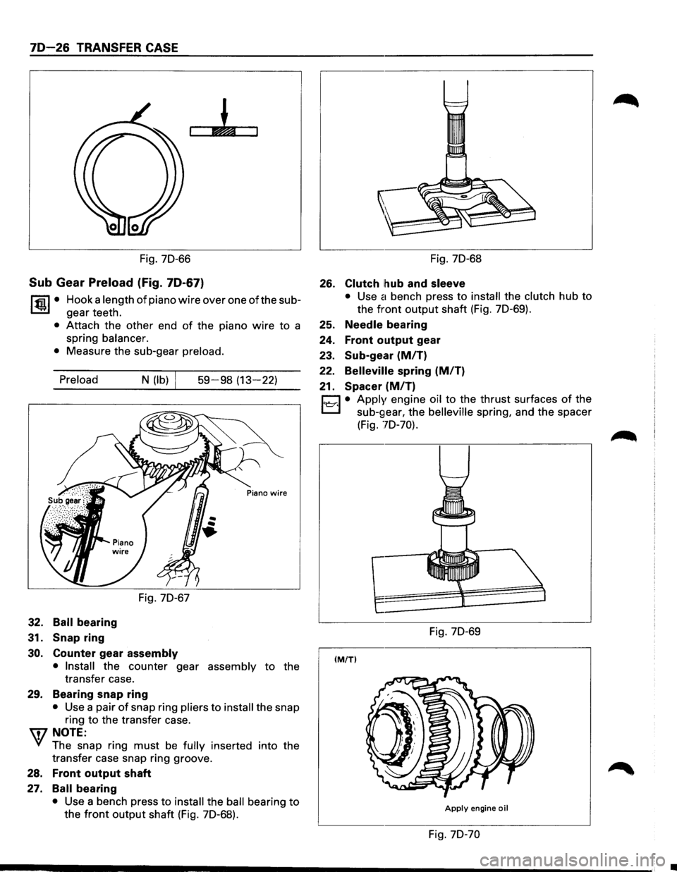
70-26 TRANSFER CASE
Fig. 70-66
Sub Gear Preload (Fig. 70-67)
~·
Hook a length of piano wire over one of the sub
gear teeth.
• Attach the other end of the piano wire to a
spring
balancer.
•
Measure the sub-gear preload.
Preload
32. Ball bearing
31.
Snap ring
N (lb)
Fig. 70-67
30. Counter gear assembly
59-98 (13-22)
• Install the counter gear assembly to the
transfer case.
29. Bearing snap ring
• Use a pair of snap ring pliers to install the snap
ring
to the transfer case.
W NOTE:
~ The snap ring must be fully inserted into the
transfer case snap ring groove.
28. Front output shaft
27. Ball bearing
• Use a bench press to install the ball bearing to
the front output shaft (Fig. 70-68).
Fig. 70-68
26. Clutch hub and sleeve
• Use a bench press to install the clutch hub to
the front output shaft (Fig. 70-69).
25. Needle bearing
24.
Front output gear
23. Sub-gear
(MIT)
22. Belleville spring (MIT)
21. Spacer (M/T)
C1 • Apply engine oil to the thrust surfaces of the
t.::::::J sub-gear, the belleville spring, and the spacer
(Fig.
70-70).
Fig. 70-69
(M/TI
Apply engine oil
Fig. 70-70
•
Page 1185 of 1928
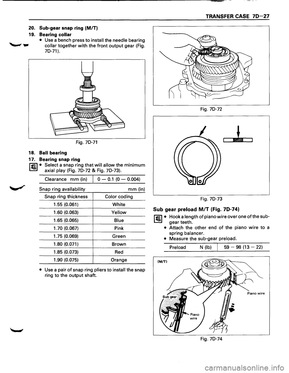
20. Sub-gear snap ring (MIT)
19. Bearing collar
• Use a bench press to install the needle bearing
collar together with the front output gear (Fig.
70-71).
Fig. 70-71
18. Ball bearing
17. Bearing snap ring
rfil • Select a snap ring that will allow the minimum
~ axial play (Fig. 70-72 & Fig. 70-73).
Clearance mm (in) 0 -0.1 (0 -0.004)
Snap ring availability mm (in)
Snap ring thickness Color coding
1.55 (0.061)
White
1.60 (0.063)
Yellow
1.65 (0.065) Blue
1. 70 (0.067)
Pink
1.75 (0.069)
Green
1.80 (0.071)
Brown
1.85 (0.073)
Red
1.90 (0.075) Orange
•
Use a pair of snap ring pliers to install the snap
ring
to the output shaft.
TRANSFER CASE 70-27
Fig. 70-72
Fig. 70-73
Sub gear preload MIT (Fig. 70-74)
~·
Hook a length of piano wire over one ofthe sub
gear teeth.
• Attach the other end of the piano wire to a
spring
balancer.
•
Measure the sub-gear preload.
Preload
N (lb) I 59 -98 (13 -22)
Fig. 70-74