oil temperature ISUZU TROOPER 1995 Owner's Manual
[x] Cancel search | Manufacturer: ISUZU, Model Year: 1995, Model line: TROOPER, Model: ISUZU TROOPER 1995Pages: 1928
Page 637 of 1928
E!) INSTALLATION
6. Radiator assembly
• Install cushion rubbers on both sides of radia
tor bottom.
• Install radiator assembly with hose, taking
care
not to damage the radiator core with a fan
blade.
5. Bracket
• Support the radiator uppertankwith the bracket
and secure the radiator.
4. Reserve tank hose
3. Fan guide, lower
2. Radiator hose
• Connect inlet hose and outlet hose to the
engine.
1. Oil cooler hose (A/T)
• Connect oil cooler hose for automatic trans-
mission.
• Connect battery ground cable.
• Pour engine coolant.
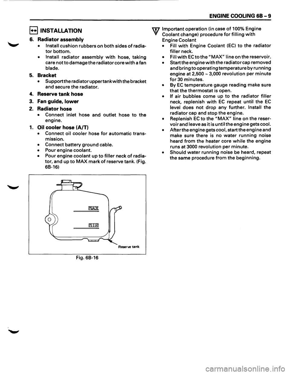
• Pour engine coolant up to filler neck of radia
tor, and up to MAX mark of reserve tank. (Fig.
68-16)
Reserve tank
Fig. 68-16
ENGINE COOLING 68-9
U7 Important operation (in case of 100% Engine
V Coolant change) procedure for filling with
Engine Coolant
• Fill
with Engine Coolant (EC) to the radiator
filler neck.
• Fill with EC to the "MAX" line on the reservoir.
• Start the engine with the radiator cap removed
and bring
to operating temperature by running
engine at
2,500-3,000 revolution per minute
for 30 minutes.
• By EC temperature gauge reading make sure
that the thermostat is open.
• If air bubbles come up to the radiator filler
neck, replenish with EC repeat until the EC
level does not drop any further. Install the
radiator cap and stop the engine.
• Replenish EC to the "MAX" line on the reser
voir and leave as it is until the engine gets cool.
• After the engine gets cool, start the engine and
make sure there is no
water running noise
heard
from the heater core while the engine
runs
at 3000 revolution per minute.
• Should water running noise be heard, repeat
the same procedure from the beginning.
Page 689 of 1928
IGNITION SYSTEM 6D4 - 1
SECTION 604
IGNITION SYSTEM
CONTENTS
General Description ...................... .
Diagnosis
................................... .
On-Vehicle Service ....................... .
Spark Plug Wire ....................... .
Spark Plug .............................. . 6D4-1
6D4-2 6D4-3
6D4-3
6D4-3
Electronic Ignition (EI) Assembly ...
Crankshaft Position Sensor
(CKP sensor) ........................ .
Torque Specifications
................ .
Main Data and Specifications
......... . 6D4-5
6D4-5
6D4-6
6D4-7
GENERAL DESCRIPTION
Ignition is done by the Electronic Ignition (EI) that
fires directly the ignition plugs from ignition coils
through spark plug wires without using a distributor.
A pair of ignition coils for the cylinders having differ
ent phases by 360° (No.1 and No.4, No.2 and No.5,
No.3 and No.6) are
fired simultaneously.
Since the cylinder on exhaust stoke requires less
energy to fire its ignition plug, energy from the
ignition coils can be utilized to fire the mating cylin
der on compression stroke. After additional 360°
rotation, respective cylinder stokes are reversed.
TheEl consists of three ignition coils, ignition control
module, crank angle sensor, Engine Control Module
(ECM) and other components.
Module is provided under the ignition coil, connected
with ECM by means of 6-pin connector. The
ignition control module turns on/off the primary
circuit of ignition coils, and also it controls the igni
tion timing at the engine
speed below 538 rpm.
A notch in
the timing disc on the crankshaft activates
the crank angle sensor which then sends information
such as firing order and starting timing of each
ignition coil to the ECM.
Further, the El employs Ignition Control (I C) to control
similar to a distributor system.
By receiving
signals such as crank position, engine
speed, water temperature and Manifold Absolute
Pressure (MAP), the ECM controls the ignition timing.
Page 703 of 1928
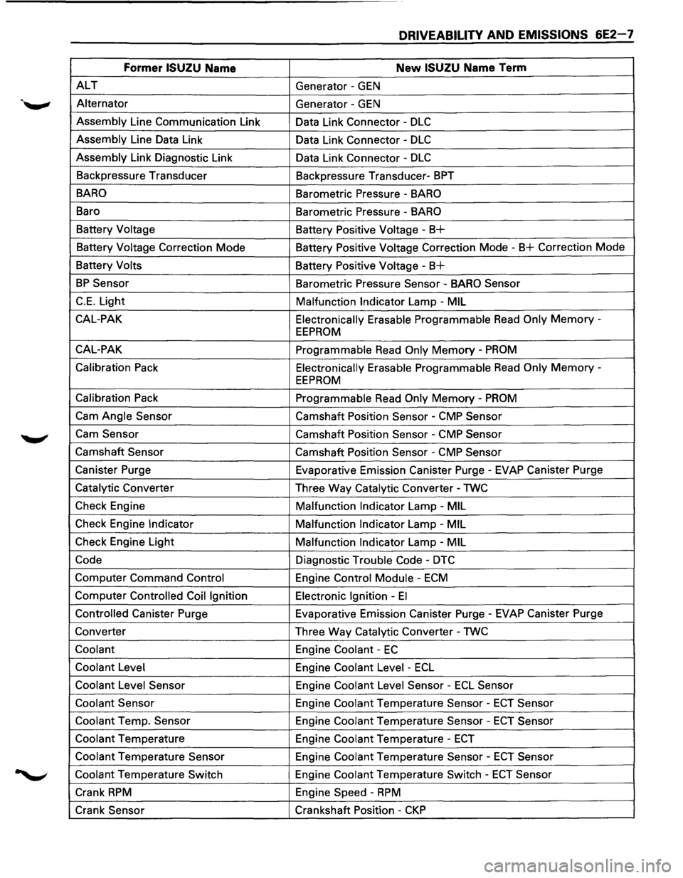
DRIVEABILITY AND EMISSIONS 6E2-7
Former ISUZU Name New ISUZU Name Term
ALT Generator -GEN
Alternator
Generator -GEN
Assembly Line Communication Link
Data Link Connector -DLC
Assembly Line Data Link
Data Link Connector -DLC
Assembly Link Diagnostic Link
Data Link Connector -DLC
Backpressure Transducer
Backpressure Transducer-BPT
BARO Barometric Pressure -BARO
Baro
Barometric Pressure -BARO
Battery Voltage
Battery Positive Voltage-B+
Battery Voltage Correction Mode Battery Positive Voltage Correction Mode -B+ Correction Mode
Battery Volts
Battery
Positive Voltage-B+
BP Sensor Barometric Pressure Sensor -BARO Sensor
C.E. Light
Malfunction Indicator Lamp -MIL
CAL-PAK Electronically
Erasable Programmable Read Only Memory -
EEPROM
CAL-PAK
Programmable Read Only Memory -PROM
Calibration Pack Electronically Erasable Programmable Read Only Memory -
EEPROM
Calibration Pack
Programmable Read Only Memory-PROM
Cam Angle Sensor Camshaft Position Sensor -CMP Sensor
Cam Sensor Camshaft Position Sensor -CMP Sensor
Camshaft Sensor Camshaft Position Sensor -CMP Sensor
Canister Purge Evaporative Emission Canister Purge-EVAP Canister Purge
Catalytic Converter
Three Way Catalytic Converter-TWC
Check Engine
Malfunction
Indicator Lamp -MIL
Check Engine Indicator Malfunction Indicator Lamp -MIL
Check Engine Light
Malfunction Indicator Lamp-MIL
Code Diagnostic Trouble Code -DTC
Computer Command Control Engine Control Module -ECM
Computer Controlled Coil Ignition Electronic Ignition -El
Controlled Canister Purge Evaporative Emission Canister Purge-EVAP Canister Purge
Converter Three Way Catalytic Converter -TWC
Coolant Engine Coolant -EC
Coolant Level
Engine Coolant Level -ECL
Coolant Level Sensor Engine Coolant Level Sensor -ECL Sensor
Coolant Sensor Engine Coolant Temperature Sensor -ECT Sensor
Coolant Temp. Sensor Engine Coolant Temperature Sensor-ECT Sensor
Coolant Temperature Engine Coolant Temperature -ECT
Coolant Temperature Sensor Engine Coolant Temperature Sensor-ECT Sensor
Coolant Temperature Switch Engine Coolant Temperature Switch -ECT Sensor
Crank RPM Engine Speed -RPM
Crank Sensor Crankshaft Position-CKP
Page 720 of 1928
6E2-24 DRIVEABILITY AND EMISSIONS
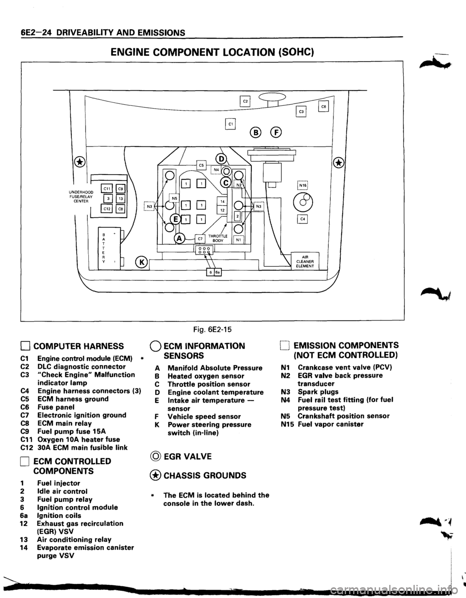
ENGINE COMPONENT LOCATION (SOHC)
UNDERHOOD
FUSE/RELAY
CENTER
8 A
T
T
E
R y
0 COMPUTER HARNESS
C1 Engine control module (ECM) *
C2 DLC diagnostic connector
C3 "Check Engine" Malfunction
indicator lamp
C4 Engine harness connectors (3)
C5 ECM harness ground
C6 Fuse panel
C7 Electronic ignition ground
CS ECM main relay
C9 Fuel pump fuse 15A
C11 Oxygen 1 OA heater fuse
C12 30A ECM main fusible link
0 ECM CONTROLLED
COMPONENTS
1 Fuel injector
2 Idle air control
3 Fuel pump relay
6 Ignition control module
6a Ignition coils
12 Exhaust gas recirculation
(EGR) VSV
13 Air conditioning relay
14 Evaporate emission canister
purge VSV
Fig. 6E2-15
Q ECM INFORMATION
SENSORS
®
A Manifold Absolute Pressure
B Heated oxygen sensor
C Throttle position sensor
D Engine
coolant temperature
E Intake air temperature -
sensor
F Vehicle speed sensor
K Power steering pressure
switch (in-line)
@ EGRVALVE
@CHASSIS GROUNDS
* The ECM is located behind the
console in the lower dash.
®
[::::J EMISSION COMPONENTS
(NOT
ECM CONTROLLED)
N1 Crankcase vent valve (PCV)
N2 EGR valve back pressure
transducer
N3 Spark plugs
N4 Fuel rail test fitting (for fuel
pressure test)
N5 Crankshaft position sensor
N15 Fuel vapor canister
Page 721 of 1928
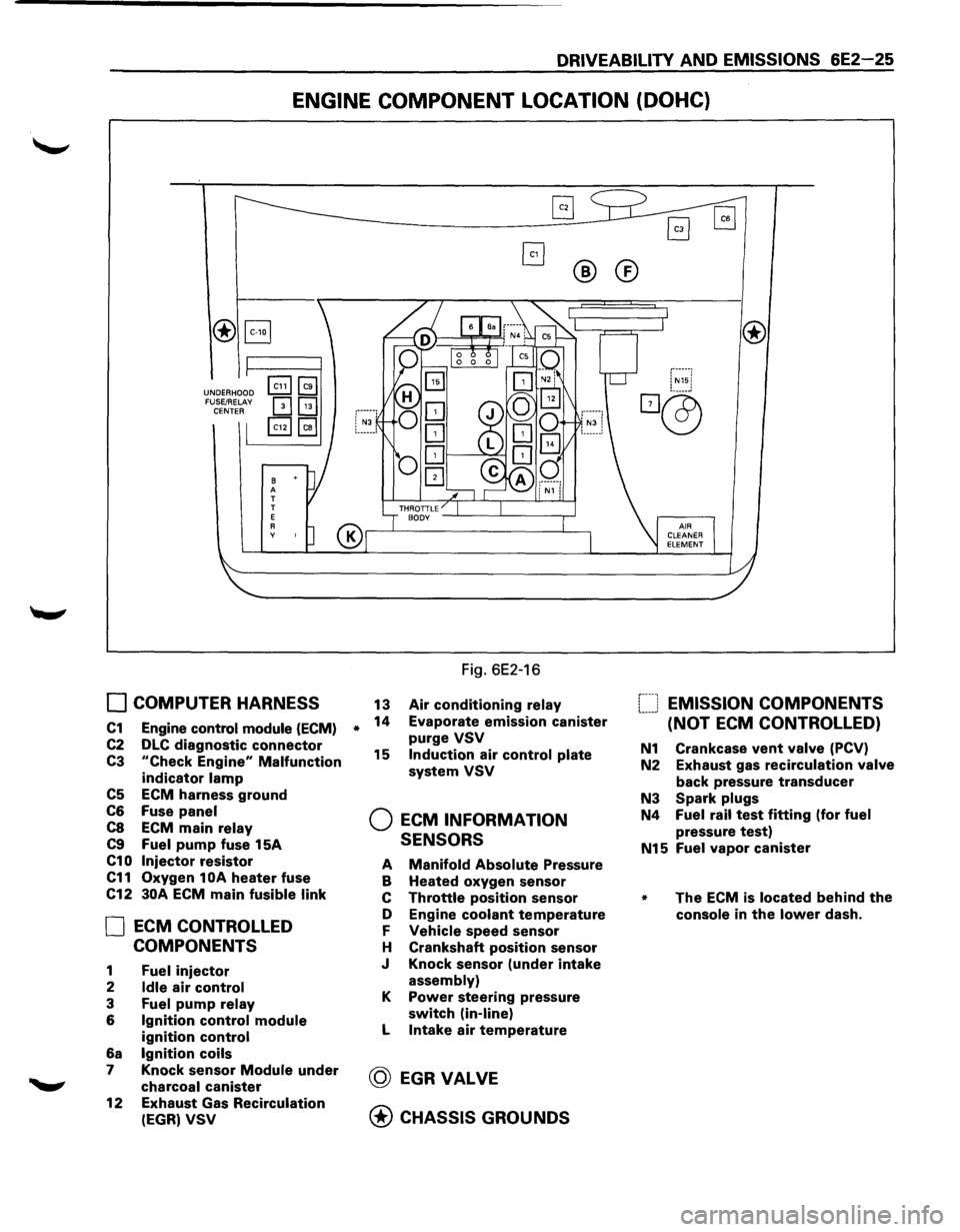
DRIVEABILITY AND EMISSIONS 6E2-25
ENGINE COMPONENT LOCATION (DOHC)
®B
UNDERHOOD FUSE/RELAY CENTER
B A T
T
E
A y
0 COMPUTER HARNESS
C1 Engine control module (ECM)
C2 DLC diagnostic connector
C3 "Check Engine" Malfunction
indicator lamp
C5 ECM harness ground
C6 Fuse panel
C8 ECM main relay
C9 Fuel pump fuse 15A
C10 Injector resistor
C11 Oxygen 1 OA heater fuse
C12
30A ECM main fusible link
0 ECM CONTROLLED
COMPONENTS
1 Fuel injector
2 Idle air control
3 Fuel pump relay
6 Ignition control module
ignition control
6a Ignition coils
7 Knock sensor Module under
charcoal canister
12
Exhaust Gas Recirculation
(EGR) VSV
*
®®
Fig. 6E2-16
13 Air conditioning relay
14 Evaporate emission canister
purge VSV
15 Induction air control plate
system VSV
Q ECM INFORMATION
SENSORS
A Manifold Absolute Pressure
B Heated oxygen sensor
c Throttle position sensor
D Engine
coolant temperature
F Vehicle speed sensor
H Crankshaft
position sensor
J Knock sensor
(under intake
assembly)
K Power steering pressure
switch (in-line)
L Intake air temperature
@ EGRVALVE
@ CHASSIS GROUNDS
f----1 EMISSION COMPONENTS !.-----' (NOT ECM CONTROLLED)
N1 Crankcase vent valve (PCV)
N2 Exhaust gas
recirculation valve
back pressure transducer
N3 Spark plugs
N4 Fuel rail test fitting (for fuel
pressure test)
N15 Fuel vapor canister
* The ECM is located behind the
console in the lower dash.
Page 722 of 1928
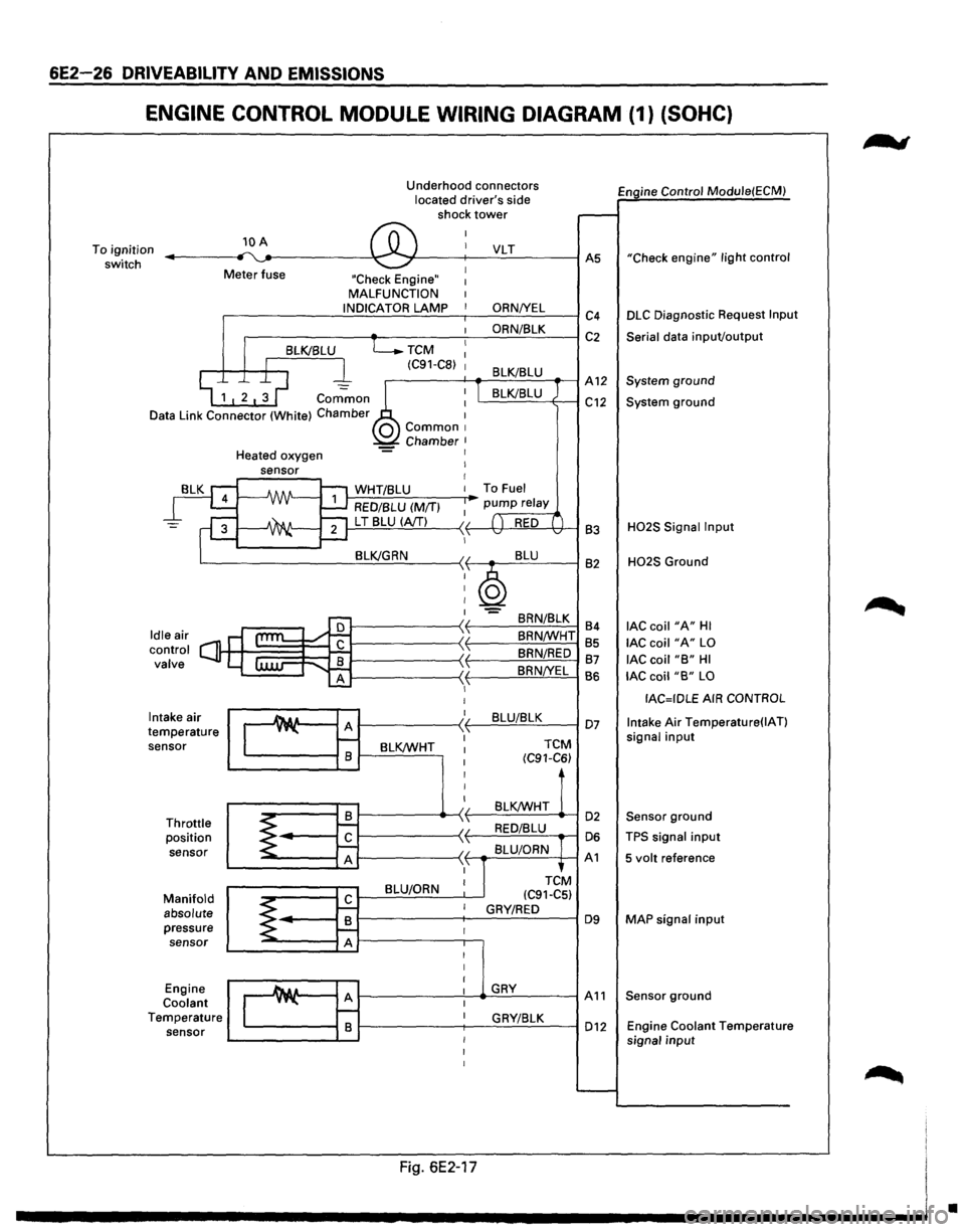
6E2-26 DRIVEABILITV AND EMISSIONS
ENGINE CONTROL MODULE WIRING DIAGRAM (1) (SOHC}
To ignition
switch 10 A
Meter fuse Underhood
connectors
located driver's side
shock tower
"Check Engine" MALFUNCTION
.-----------..:.:.1 N.:.:D:..:.IC=A~T~O:..:.R.:....=:.LA..::.M.:..::P:..___-,--___.:O:..:.R.:.:.N::.._IY.....:E:..:L=----1 c4
.------~~----~~O:..:R:..:N/~8~L=-=K--~ C 2
TCM
(C91-C8)
Engine Control Module(ECM)
"Check
engine" light control
DLC Diagnostic Request Input
Serial
data inpuVoutput
.--------f---+-....::...::;_;__=---_-1 A 12 System ground
Common
Data Link Connector (White) Chamber L.....::.=::....=..:=-=----+---1 C12 System ground
Intake air
temperature sensor
Throttle position
sensor
Manifold absolute pressure sensor
Engine
Coolant Temperature sensor Heated
oxygen
J-,.:..:W:.:..H.:..:T.:.:I8:..:L:.:U:......__ __ ....-To Fuel
RED/BLU (M/T)
1---=-'L T'-.!8~L:!:U'--l(.::::A/T!....!...!....) ---< f------lt+-~!,!..._'H---1 83
BRN/8LK
84
8RN/WHT 85
BRN/RED 87
8RN!YEL
BS
1---------~~~B~L~U~/8~L~K~--I 07
BLK/WHT
TCM
(C91-C6)
BLK/WHT 1------------4>---< t-----=~:..:.:..:_.:..:_ ....... -1 02
1-----------~ f----'-=-'-==--....-1 06
1-----------~ f--.-::..:=.=.:....=..c~-+--1 A 1
BLU/ORN
H02S Signal Input
H02S Ground
lAC coil "A" HI
lAC coil "A" LO
lAC coil "B" HI
lAC coil "B" LO
IAC=IDLE AIR CONTROL
Intake
Air Temperature(IAT)
signal input
Sensor ground
TPS signal input
5 volt reference
MAP
signal input
1---------'----...._.G:=.:..:.RY-=--------1 A 11 Sensor ground
1-------;---.:::G:..:R_;_YI:...::8:..:L::..:K:__---I 012 Engine Coolant Temperature
signal input
Fig. 6E2-17
•
Page 729 of 1928
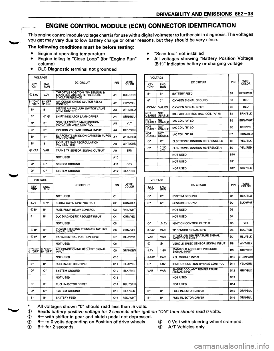
DRIVEABILITY AND EMISSIONS 6E2-33
ENGINE CONTROL MODULE (ECM) CONNECTOR IDENTIFICATION
This engine control module voltage chart is for use with a digital voltmeter to further aid in diagnosis. The voltages
you get may vary due to low battery charge or other reasons, but they should be very close.
The following conditions must be before testing:
• Engine at operating temperature • "Scan tool" not installed
•
Engine idling in "Close Loop" (for "Engine Run"
column) •
All voltages showing "Battery Position Voltage
(8+)" indicates battery or charging voltage
•
DLC Diagnostic terminal not grounded
VOLTAGE VOLTAGE
DC CIRCUIT PIN WIRE
KEY ENG. COLOR
"ON" RUN
DC CIRCUIT PIN WIRE
KEY ENG. COLOR "ON" RUN
ID 5.0V 5.0V THROTILE
POSITION ~TP~ SENSOR & MANIFOLD ABSOLUT P ESSURE A1 BLU/ORN 8+ B+ BATIERY FEED B1 RED/WHT
5 VOLT REFERENCE B+"ON" B+ OFF AIR CONDITIONING CLUTCH RELAY A2 GRY/YEL 0 "OFF" 0* ON
CONTROL o• o• OXYGEN SIGNAL GROUND 82 BLU
B+ s+ INTAKE
AIR VACUUM SWITCH VALVE A3 WHT/BLU (VSV) CONTROL
o• O*® SHIFT INDICATOR LAMP DRIVER A4 ORN/BLU .430MV
VALlES OXYGEN
SIGNAL INPUT
B3 RED
NOT NOT
IDLE AIR CONTROL (lAC) COIL "A" HI B4 8RN/BLK USABLE
USABLE
o• B+ "CHECK ENGINE" MALFUNCTION A5 VLT INDICATOR LAMP CONTROL
B+ B+ IGNITION VOLTAGE SIGNAL INPUT
AS RED/GRN
NOT NOT
lAC COIL "A" LO B5 8RN/WHT USABLE USABLE
NOT NOT
lAC COIL
"B" LO B6 BRN/YEL USABLE
USABLE
B+ B+ EVAPORATE EMISSION CANISTER PURGE A7 WHT/RED VSVCONTROL NOT
NOT
lAC COIL "B" HI B7 BRN/RED USABLE
USABLE
B+ 8~ EXHAUST GAS RECIRCULATION AS WHT/GRN VSV CONTROL
@VAR VAR TRANS TP SENSOR SIGNAL OUTPUT A9 8RN
o• o• ELECTRONIC IGNITION REFERENCE LO 88 YEL/BLK
o• 1.1V-ELECTRONIC
IGNITION REFERENCE HI B9 YEL/RED
2.4V
NOT USED B10
NOT USED
A10
NOT USED
B11 o• o• SENSOR GROUND A11 GRY
NOT USED B12 GRY/BLU o• o• SYSTEM
GROUND A12 8LK/PNK
VOLTAGE
VOLTAGE
DC CIRCUIT PIN WIRE
KEY ENG. COLOR DC CIRCUIT PIN WIRE
KEY ENG. COLOR "ON" RUN "ON" RUN
NOT USED C1 o• o• SYSTEM GROUND D1 BLK/BLU
4.7V 4.7V
SERIAL DATA INPUT/OUTPUT C2 ORN/8LK o• 0* SENSOR GROUND D2 BLK/WHT
@) B+ B+ FUEL PUMP RELAY CONTROL C3 PNK/WHT NOT USED D3
B+ B+ DLC DIAGNOSTIC REQUEST INPUT C4 ORN/YEL NOT USED D4
NOT USED C5 o• .1·.2V IGNITION
CONTROL OUTPUT D5 YEL
@B+ B+ POWER STEERING PRESSURE SWITCH C6 GRN/YEL SIGNAL INPUT 0.54V VAR
TP SENSOR
SIGNAL INPUT D6 BLU/RED
@O* o• PARK/NEUTRAL POSITION
INPUT C7 BLU/PNK VAR
VAR INTAKE AIR TEMPERATURE SIGNAL D7 BLU/BLK INPUT D7 BLU/BLK
NOT USED CB ® ® VEHICLE SPEED SENSOR
SIGNAL INPUT D8 WHT/BLK
B+"ON" 0 "ON" AIR CONDITIONING REQUEST SIGNAL C9 GRN/ORN
0 "OFF" B+"OFF"
INPUT 4.7V 1-2V MANIFOLD ABSOLUTE PRESSURE D9 GRY/RED SIGNAL
INPUT
NOT USED
C10 8-10V
VAR K.S.
MODULE INPUT D10 LTGRN/WHT
B+ B+ FUEL INJECTOR
DRIVER C11 BLU/YEL o• 4.9V IGNITION CONTROL BYPASS CONTROL D11 YELIGRN
o• o• SYSTEM GROUND
C12 BLK/PNK VAR VAR ENGINE COOLANT TEMPERATURE
D12 GRY/BLK SIGNAL
INPUT
NOT USED
C13 NOT USED D13
B+ 8+
FUEL INJECTOR DRIVER C14 BLU/GRN NOT USED D14
o• o• SYSTEM GROUND
C15 BLK/BLU B+ B+ FUEL INJECTOR DRIVER D15 ORN/BLU
8+ B+ BATIERY FEED C16 RED/WHT B+ 8+
FUEL INJECTOR DRIVER D16 ORN/8LU
* All voltages shown "0" should read less than .5 volts.
Reads battery positive voltage for 2 seconds after ignition "ON" then should read 0 volts. CD
®
® @
B+ with shifter in gear and clutch pedal not depressed.
B+ to 0 volts depending on Position of drive wheels
B+ for 2 seconds.
@
®
0 Volt with steering wheel cramped.
A/T Vehicles only
Page 786 of 1928
6E2-90 DRIVEABILITY AND EMISSIONS
INTERMITTENTS
Definition: Problem may or may not turn "ON" the
"Check Engine" malfunction indicator lamp or store
Diagnostic
Trouble Code (DTC).
DO NOT use the DTC charts in "Engine Components/
Wiring Diagrams/Diagnostic
Charts," Section "6E2-A"
for intermittent problem. The fault must be present to
locate the problem. If a fault is intermittent, use of DTC
charts may result in replacement of good parts.
•
• Most intermittent problems are caused by faulty
electrical
connections or wiring. Perform careful
visual/physical
check as described at start of
"Symptoms," Section "6E2-B." Check for:
Poor mating
of the connector halves. or
terminal not fully seated in the connector body
(backed out).
Improperly formed or damaged terminal. All
connector
terminals in the problem circuit
should be carefully reformed or replaced to
insure proper contact tension.
Poor
terminal to wire connection. This
requires removing the
terminal from the
connector body to check. Refer to
SECTION 8
"Wiring Harness Service,"
If a visual/physical check does not find the cause
of the problem, the car can be driven with a
voltmeter connected to a suspected circuit. A
"Scan tool" can also be used to help detect
intermittent conditions. An abnormal
voltage, or
"Scan" tool reading, when the problem occurs,
indicates the
problem may be in that circuit. If the wiring
and connectors check
OK, and a DTC was
stored
for a circuit having a sensor, except for
DTC(s) 44 and 45, substitute a known good sensor
and recheck.
• Loss of DTC memory. To check, disconnect
throttle position (TP) sensor and idle engine until
"Check
Engine" malfunction indicator lamp comes
"ON". DTC 21 should be stored, and kept in
memory when ignition is turned "OFF". If not, the
Engine
Control Module (ECM) is faulty.
•
An intermittent "Check Engine" malfunction
indicator
lamp with no stored DTC may be caused
by:
Ignition coil shorted to ground and arcing at
spark
plug wires or plugs.
"Check
Engine" malfunction indicator lamp
wire to ECM shorted to ground.
Diagnostic
"test" terminal wire to ECM,
shorted to ground.
ECM grounds, refer to ECM wiring diagrams.
• Check for an electrical system interference caused
by a defective
relay, ECM driven solenoid, or
switch. They can cause a sharp electrical surge.
Normally, the problem will occur when the faulty
component is operated.
• Check for improper installation of electrical
options such as lights, 2 way radios, etc.
• Ignition control wires should be routed away from
spark plug wires, electronic ignition (EI) wires, El
housing, coil and generator. Ground wire from
ECM to El should have a good connection.
• If problem has not been found, refer to "ECM
Connector Symptom" charts at the end of
"Symptoms," Section "6E2-B."
HARD START
Definition: Engine cranks OK, but does not start for a
long time. Does eventually run, or may
start
but immediately dies.
PRELIMINARY CHECKS
• Perform the careful visual/physical checks as
described at start of "Symptoms," Section "6E2-
B".
•
Make sure the driver is using the correct starting
procedure.
SENSORS
• CHECK: Engine coolant temperature sensor using
a
"Scan tool", compare engine coolant
temperature with ambient temperature
on
cold engine. -
If engine coolant temperature
readings
is 5 degrees greater than or less than
ambient air temperature on a
cold
engine, check resistance in engine
coolant temperature sensor circuit
or
sensor itself. Compare engine coolant
temperature sensor resistance value
to the "Diagnostic Aids" chart on
DTC
14 chart.
• CHECK: Manifold absolute pressure sensor.
Check for flooding and/or correct sensor
for vehicle.
• CHECK: TP sensor for binding or a high TP sensor
voltage with the throttle closed (should
read between 0.54 volt and 1.25 volts.)
Page 792 of 1928
6E2-96 DRIVEABILITY AND EMISSIONS
EXCESSIVE EXHAUST EMISSIONS OR ODORS
Definition: Vehicle fails an emission test. Vehicle has
excessive
"rotten egg" smell. Excessive
odors
do not necessarily indicate
excessive emissions.
PRELIMINARY CHECKS
• Perform on-board diagnostic system check.
• IF EMISSION TEST shows excessive CO and
hydrocarbon check items which cause car to run
RICH (Long Term Fuel Trim less than 118), refer to
"Diagnostic Aids" on facing page of diagnostic
trouble code (DTC) 45.
• If EMISSION TEST shows excessive NOx, check
items which cause car
to run lean or too hot.
COOLING SYSTEM
• If the "Scan tool" indicates a very high engine
coolant temperature and the system is running
lean:
CHECK: Engine coolant level
CHECK: Engine thermostat for faulty part
(always open) or for wrong heat range. Refer
to
ENGINE COOLING (SECTION 68).
CHECK: Cooling fan operation.
FUEL SYSTEM
• NOTICE: If the system is running rich (L.T. Fuel
Trim near 118), refer to "Diagnostic Aids"
on facing page
of DTC 45.
-
If the system is running lean (L.T. Fuel
Trim near 142) refer to "Diagnostic
Aids" on facing page of DTC 44.
• CHECK: For properly installed fuel cap.
• CHECK: Fuel pressure. Use CHART A-7.
• CHECK: Canister for fuel loading. Refer to
"Evaporative Emission Control System,"
Section
"6E2-C3."
IGNITION SYSTEM
• CHECK: Ignition timing. Refer to "Vehicle
Emission Control Information" label.
• CHECK: Spark plugs, plug wires, and ignition
components. Refer to
ENGINE
ELECTRICAL (SECTION 6D).
ADDITIONAL CHECKS
• CHECK: For vacuum leaks.
• CHECK: Exhaust gas recirculation valve for not
opening. Use CHART C-7.
• CHECK: For lead contamination of three way
catalytic converter (look for the removal
of fuel filler neck restrictor).
• CHECK: Carbon build-up. Remove carbon with
top engine cleaner. Follow instructions
on can.
• CHECK: PCV valve for being plugged, stuck or
blocked PCV hose or fuel in the
crankcase.
BACKFIRE
Definition: Fuel ignites in intake manifold, or in
exhaust system, making
loud popping
noise.
PRELIMINARY CHECKS
• Perform the careful visual/physical checks as
described at start of "Symptoms," Section "6E2-
B."
IGNITION SYSTEM
• CHECK: Proper ignition coil output voltage with
spark tester J26792 or equivalent (ST-
125).
• CHECK: Spark plugs. Remove spark plugs, check
for
wet plugs, cracks, wear, improper
gap, burned
electrodes, or heavy
deposits. Repair
or replace as necessary.
• CHECK: Spark plug wires for crossfire, also
inspect electronic ignition, spark plug
wires, and proper routing of plug wires.
• CHECK: Ignition timing. Refer to "Vehicle
Emission Control Information" label.
• CHECK: If an intermittent condition exists in the
ignition system, see
"Ignition System/
IGNITION CONTROL," Section "6E2-C4"
or ENGINE ELECTRICAL (SECTION 6D).
ENGINE MECHANICAL
• CHECK: Compression- Look for sticking or leaking
valves.
• CHECK: Valve timing, refer to ENGINE
MECHANICAL DIAGNOSIS (SECTION
6A).
• CHECK: Intake and exhaust manifold passages for
casting
flash.
FUEL SYSTEM
• CHECK: Perform fuel system diagnosis check, see
CHART A-7.
Page 820 of 1928
6E2-124 DRIVEABILITV AND EMISSIONS
E) REMOVAL
Preparation: • Engine hood
• Battery negative cable
1.
Air cleaner assy
2.
Accelerator pedal cable
•
Disconnect from throttle body and cable
brackets.
3. Canister vacuum hose
• Disconnect from vacuum switch valve (VSV).
4. Vacuum booster hose
• Disconnect from Common chamber duct.
5. Connectors
• Disconnect idle air control valve, throttle
position sensor, manifold absolute pressure,
canister
VSV, exhaust gas recirculation (EGR)
VSV, intake air temperature and VSV.
6. High tension cable
• Remove from cylinder heads.
7. Electronic ignition (EI) module assy
• Disconnect 3 connector from El module.
• Remove 3 bolts from El bracket and El assy.
8.
Throttle body (TB)
• Remove 4 bolts from TB.
9. Vacuum hoses
• Disconnect canister VSV and EGR VSV vacuum
hose
from TB.
10. Fuel pressure control valve vacuum hose
• Disconnect from common chamber duct.
11.
PCV hose
• Disconnect from common chamber duct.
12.
Evaporate emission canister purge hose
• Disconnect from common chamber duct.
13.
EGR valve assy
• Remove 4 bolts from common chamber duct
and exhaust manifold.
14.
Common chamber duct
• Remove 4 bolts, 4 nuts and 3 duct bracket fixing
bolts.
• Remove ground cable fixing bolt from rear of
common chamber duct.
15.
Common chamber
• Remove 6 bolts and 2 nuts.
• Remove common chamber bracket fixing bolts
from rear of common chamber.
16. Fuel
hose
• Feed and return hose from fuel pipe and 2 fixing
bolts
from cylinder head. 17.
Fuel
rail assembly
• Remove fuel injector connector.
• Remove fuel rail fixing bolts.
• Remove fuel rail assy.
j .. !•l DISASSEMBL V
NOTE:
• If
an injector becomes separated from the rail and
remains in the cylinder head, both injector
0-ring
seals and the retainer clip must be replaced.
1.
Regulator attaching screw
2. Fuel pressure control valve assembly
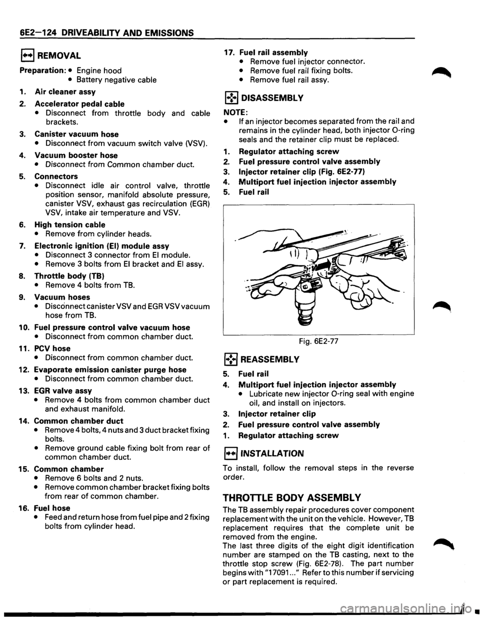
3. Injector retainer clip (Fig. 6E2-77)
4.
Multipart fuel injection injector assembly
5. Fuel rail
Fig. 6E2-77
l•! .. j REASSEMBL V
5. Fuel rail
4. Multipart fuel injection injector assembly
• Lubricate new injector 0-ring seal with engine
oil, and
install on injectors.
3.
Injector retainer clip
2. Fuel pressure control valve assembly
1. Regulator attaching screw
l·u·jiNSTALLATION
To install, follow the removal steps in the reverse
order.
THROTTLE BODY ASSEMBL V
The TB assembly repair procedures cover component
replacement
with the unit on the vehicle. However, TB
replacement requires that the complete unit be
removed from the engine.
The last three digits
of the eight digit identification
number are stamped on the
TB casting, next to the
throttle stop screw (Fig. 6E2-78). The part number
begins
with "17091 ... " Refer to this number if servicing
or part replacement is required.
•