engine oil capacity ISUZU TROOPER 1995 Workshop Manual
[x] Cancel search | Manufacturer: ISUZU, Model Year: 1995, Model line: TROOPER, Model: ISUZU TROOPER 1995Pages: 1928
Page 92 of 1928
1 D-4 COMPRESSOR OVERHAUL
6. Perform oil return operation.
7. Remove the compressor and recheck the
amount of oil.
8. Adjust the compressor oil, if necessary.
Collected Amount
more than 90cc
(3.0
fl.oz.)
Charging Amount
same as collected amount
less than 90cc (3.0 fl.oz.) 90cc (3.0 fl.oz.)
Checking and Adjusting for Compressor
Replacement
150cc (5.0 fl.oz.) of oil is charged in compressor
(service parts).
So it is necessary to drain the
proper
amount of oil from the new compressor.
1. Perform oil return operation.
2. Discharge and recover refrigerant and remove
the compressor.
3. Drain the compressor oil and measure the
extracted
oil.
4. Check the compressor oil for contamination.
5. Adjust oil level as required.
Amount of oil drained
from used compressor
less than 90cc
(3.0
fl.oz.)
Draining amount of oil
from new compressor
Same as drained
amount
more than 90cc (3.0 fl.oz.) 90cc (3.0 fl.oz.)
6. Evacuate, charge and perform oil return oper
ation.
7. Check system operation.
CONTAMINATION OF COMPRESSOR OIL
Unlike engine oil, no cleaning agent is added to the
compressor
oil. Even if the compressor runs for a
long period
of time (approximately 1 season), the
oil never becomes contaminated as long
as there is
nothing
wrong with the compressor or its method
of use.
Inspect the extracted oil for any of the following
conditions:
• The capacity of the oil has increased.
• The oil has changed color to red.
• Foreign substances, metal powder, etc., are
present in the oil.
If any of these conditions exists, compressor oil
is contaminated. Whenever contaminated com
pressor
oil is discovered, the receiver/dryer must
be
replaced.
OIL RETURN OPERATION
There is close affinity between the oil and the
refrigerant. During normal operation, part
of the oil
recirculates
with the refrigerant in the system.
When checking the
amount of oil in the system, or
replacing any component of the system, the com
pressor
must be run in advance for oil return oper
ation. The procedure is as
follows:
1. Open the all doors and engine hood.
2. Start the engine and air conditioning switch is
"ON" and Set the fan control knob at its hig
hest position.
3. Run the compressor for more than 20 minutes
between
800 and 1,000 rpm in order to operate
the system.
4. Stop the engine.
REPLACEMENT OF COMPONENT PARTS
When replacing system component parts, supply
the following
amount of oil to the component parts
to be installed.
Component parts to be installed Amount of oil
Evaporator 50cc
(1.7
fl.oz.)
Condenser 30cc
(1.0 fl.oz.)
Receiver/dryer 30cc
(1.0 fl.oz.)
Refrigerant line (one piece) 1 Occ (0.3 fl. oz.)
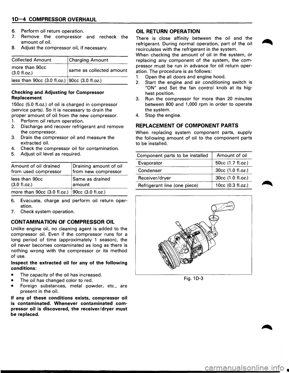
Fig. 1 D-3
•
Page 621 of 1928
·-------------------------------------
ENGINE (V6 3.2L DOHC AND SOHC) 6A1-63
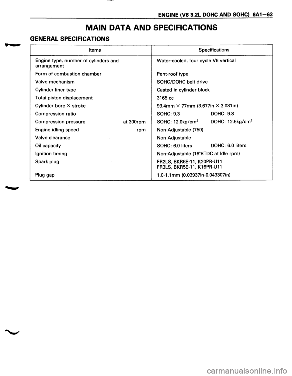
MAIN DATA AND SPECIFICATIONS
GENERAL SPECIFICATIONS
Items S pacifications
Engine type,
number of cylinders and Water-cooled, four cycle V6 vertical
arrangement
Form
of combustion chamber
Pent-roof type
Valve mechanism SOHC/DOHC belt drive
Cylinder liner type
Casted in cylinder block
Total
piston displacement
3165 cc
Cylinder bore X stroke 93.4mm X 77mm (3.677in X 3.031 in)
Compression ratio
SOHC: 9.3 DOHC: 9.8
Compression pressure
at
300rpm SOHC: 12.0kg/cm2 DOHC: 12.5kg/cm2
Engine idling speed rpm Non-Adjustable (750)
Valve clearance Non-Adjustable
Oil capacity SOHC: 6.0 liters DOHC:
6.0 liters
Ignition
timing Non-Adjustable (16.BTDC at Idle rpm)
Spark
plug FR2LS, BKR6E-11, K20PR-U11
FR3LS, BKR5E-11 I K16PR-U11
Plug gap 1.0-1.1 mm (0.03937in-0.043307in)
Page 630 of 1928
68 - 2 ENGINE COOLING
The cooling system is a pressurized Engine Coolant
(EC) forced circulation type which consists of water
pump, thermostat cooling fan, radiator and other
components. The automatic transmission fluid is
cooled by the EC in radiator.
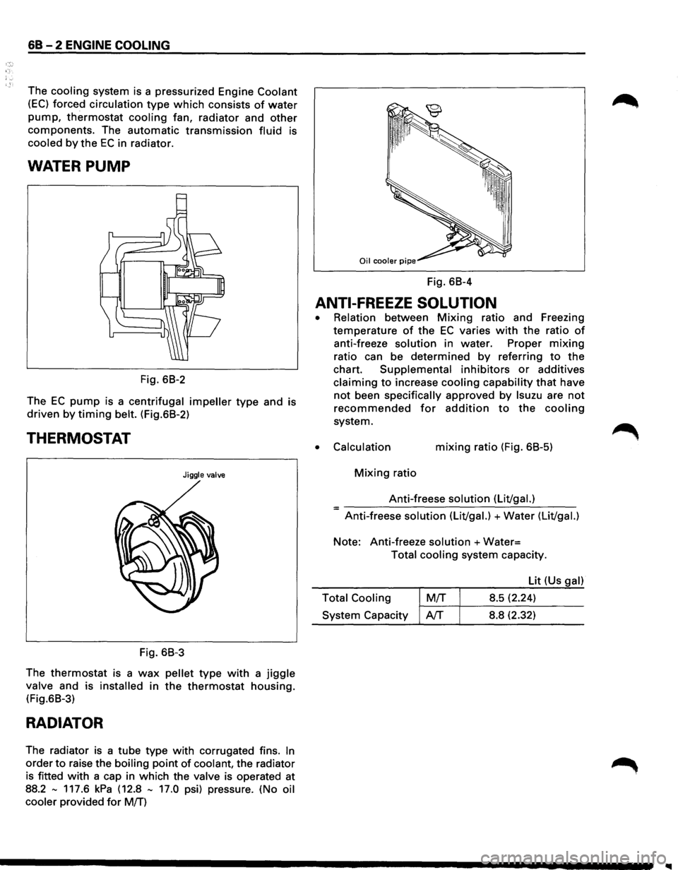
WATER PUMP
Fig. 68-2
The
EC pump is a centrifugal impeller type and is
driven by timing belt. (Fig.68-2)
THERMOSTAT
Jiggle valve
Fig. 68-3
The
thermostat is a wax pellet type with a jiggle
valve and is installed in the thermostat housing.
(Fig.68-3)
RADIATOR
The radiator is a tube type with corrugated fins. In
order to raise the boiling point of coolant, the radiator
is fitted
with a cap in which the valve is operated at
88.2
-117.6 kPa (12.8 - 17.0 psi) pressure. (No oil
cooler
provided for M!f)
Fig. 68-4
ANTI-FREEZE SOLUTION
•
•
Relation between Mixing ratio and Freezing
temperature
of the EC varies with the ratio of
anti-freeze solution in water. Proper mixing
ratio can be determined by referring to the
chart. Supplemental inhibitors or additives
claiming to increase cooling capability that have
not been specifically approved by lsuzu are not
recommended for addition to the cooling
system.
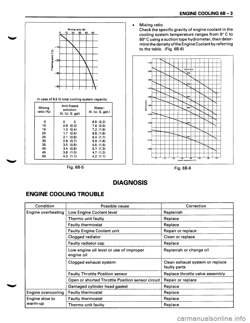
Calculation mixing ratio (Fig. 68-5)
Mixing ratio
Anti-freese
solution (Lit/gal.) =-----------------Anti-freese solution (Lit/gal.) +Water (Lit/gal.)
Note: Anti-freeze solution +Water=
Total cooling system capacity.
Lit (Us
gal)
Total Cooling
M!f 8.5 (2.24) ~-~~--------System Capacity AfT 8.8 (2.32)
Page 631 of 1928
Mixing ratio(%) 0 10 20 30 40 50
~
' -10
'
1
' -30
~ -40
In case of 8.5 lit total cooling system capacity
Mixing Anti-freeze
Water: solution: ratio (%) lit. (U.S. gal) lit. (U.S. gal.)
0 0 0
8.5 (2.2) 10 0.9 (0.3) 7.6 (2.0) 15
1.3 (0.4) 7.2 (1.9) 20 1.7 (0.5) 6.8 (1.8)
25 2.1 (0.6) 6.4 (1.7) 30 2.6 (0.7) 5.9 (1.6)
35 3.0 (0.8) 5.5
(1.5) 40 3.4 (0.9) 5.1 (1.3)
45 3.8 (1.0) 4.7 (1.2) 50 4.3 (1.1)
4.2 (1.1)
Fig. 68-5
ENGINE COOLING 68-3
• Mixing ratio
Check
the specific gravity of engine coolant in the
cooling system temperature ranges from oo C to
50° C using a suction type hydrometer, then deter
mine the densityofthe Engine Coolant by referring
to the table. (Fig. 68-6)
1,100 1'-........ ........ ...... .............. Mixing ratio
~"""--r-... 1'-""' 1,1)90
........ ...... ........ ........ .......... '
1,000
'"" 1,07 o......_ 1'-........ I'-.......... I"-........ .......
I"-........ ..........
................. I"-........
'
1,080
....... I"-........ ~ ........ ......
........ "'" ~"""--r--..... 1,050
r-. ........ ~ .......... ......
---
........ ........ 1,040
r-.... !'--.. 1'-0 '"" ~"""--1'-.... ........ 1,03
1--....... ........ r--~ ........
'
1,020
....... ~ 1'-0 ~"""---.... 1,01
...... ,
'
1,000
10 20 30 40 50 60 70 Coolant temperature ("C)
Fig. 68-6
DIAGNOSIS
ENGINE COOLING TROUBLE
Condition Possible cause Correction
Engine
overheating Low Engine Coolant level Replenish
Thermo unit faulty Replace
Faulty
thermostat Replace
Faulty
Engine Coolant unit Repair or replace
Clogged
radiator Clean or replace
Faulty
radiator cap Replace
Low engine oil level or use of improper Replenish or change oil
engine oil
Clogged exhaust system Clean exhaust system or replace
faulty parts
Faulty Throttle Position sensor Replace throttle valve assembly
Open or shorted Throttle Position sensor circuit Repair or replace
Damaged cylinder head gasket Replace
Engine overcooling Faulty thermostat Replace
Engine slow to Faulty thermostat Replace
warm-up Thermo unit faulty Replace
Page 861 of 1928
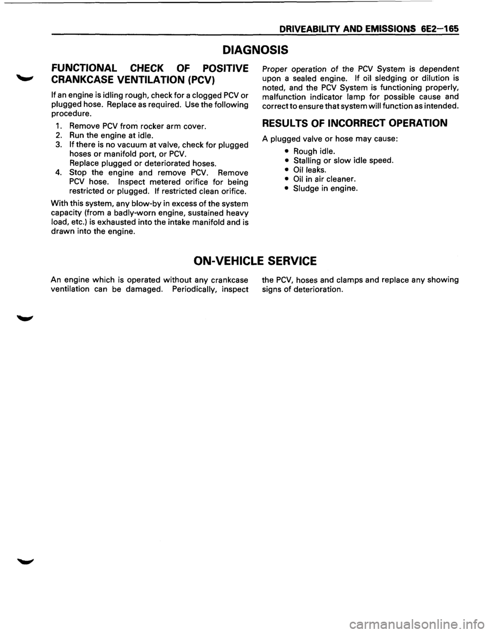
DRIVEABILITV AND EMISSIONS 6E2-165
DIAGNOSIS
FUNCTIONAL CHECK OF POSITIVE
CRANKCASE VENTILATION (PCV)
If an engine is idling rough, check for a clogged PCV or
plugged hose. Replace as required. Use the following
procedure.
1. Remove PCV from rocker arm cover.
2. Run the engine at idle.
3. If there is no vacuum at valve, check for plugged
hoses or manifold port, or PCV.
Replace plugged or deteriorated hoses.
4. Stop the engine and remove PCV. Remove
PCV hose. Inspect metered orifice for being
restricted or
plugged. If restricted clean orifice.
With this system, any
blow-by in excess of the system
capacity (from a
badly-worn engine, sustained heavy
load, etc.) is exhausted into the intake manifold and is
drawn into the engine. Proper
operation
of the PCV System is dependent
upon a
sealed engine. If oil sledging or dilution is
noted, and the PCV System is functioning properly,
malfunction
indicator lamp for possible cause and
correct to ensure that system
will function as intended.
RESULTS OF INCORRECT OPERATION
A plugged valve or hose may cause:
• Rough idle.
• Stalling
or slow idle speed.
• Oil leaks.
• Oil
in air cleaner.
• Sludge
in engine.
ON-VEHICLE SERVICE
An engine which is operated without any crankcase
ventilation can be damaged. Periodically, inspect the
PCV, hoses
and clamps and replace any showing
signs
of deterioration.
Page 1129 of 1928
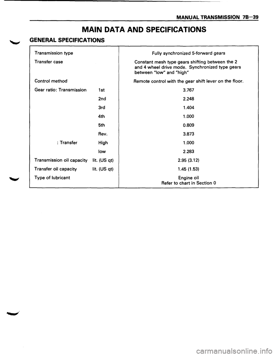
MANUAL TRANSMISSION 78-39
MAIN DATA AND SPECIFICATIONS
GENERAL SPECIFICATIONS
Transmission type
Transfer case
Control method
Gear ratio: Transmission
1st
2nd
3rd
4th
5th
Rev.
:Transfer High
low
Transmission oil capacity lit. (US qt)
Transfer
oil capacity lit. (US qt)
Type
of lubricant Fully
synchronized
5-forward gears
Constant mesh type gears shifting between the
2
and 4 wheel drive mode. Synchronized type gears
between
"low" and "high"
Remote control with the gear shift lever on the floor.
3.767
2.248
1.404
1.000
0.809
3.873
1.000
2.283
2.95
(3.12)
1.45 (1.53)
Engine oil
Refer to chart in Section 0
Page 1187 of 1928
TRANSFER CASE 70-29
1. Bearing snap ring
Fig. 70-79
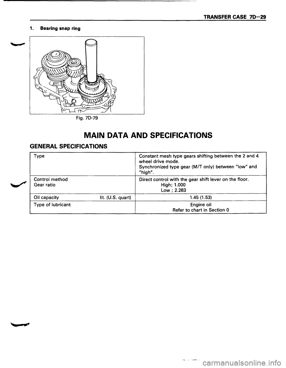
MAIN DATA AND SPECIFICATIONS
GENERAL SPECIFICATIONS
Type Constant mesh type gears shifting between the 2 and 4
wheel drive mode.
Synchronized type gear
(M/T only) between "low" and
"high".
Control method Direct control with the gear shift lever on the floor.
Gear ratio
High; 1.000
Low; 2.283
Oil capacity lit. (U.S. quart) 1.45 (1.53)
Type of lubricant Engine oil
Refer to chart in Section
0
Page 1211 of 1928
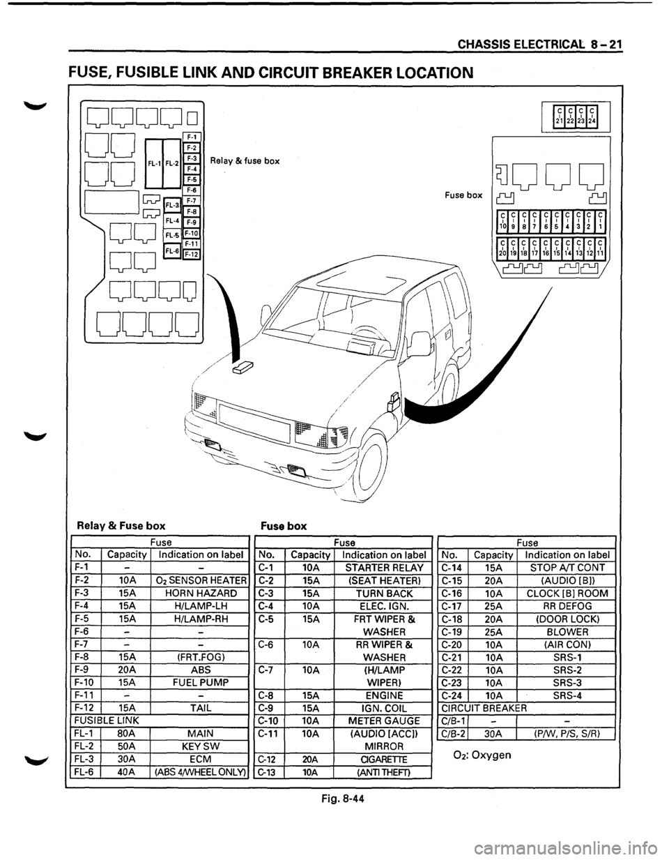
CHASSIS ELECTRICAL 8-21
FUSE, FUSIBLE LINK AND CIRCUIT BREAKER LOCATION
ooooo 112~12~1~1~1
00 E
EEr 00 ~
Relay & fuse box
SJOOO 7-6
I lw ;;::;~ Fuse box ~ ~
1l1~~ ~lff~UIH~Inll
w~ F-a FL-4 ~
00 FL·S~ r---, F-11 'l2~J1~ 1~1&11~11~1,\l~31hl1~1
0
0
FL-6 'F-i2
I' ~
\a~ a~;
0000
0000
I ~
l/
~
j
~/~/ e:;?' v II I / / .I / /
('-/ .
~~
-~-~;,a~ ~~ --.:_
~~~~ -
Relay & Fuse box Fuse box
Fuse
Fuse Fuse
No. Capacity Indication on label No. Capacity Indication on label No. Capacity Indication on label
F-1 --C-1 10A STARTER RELAY
C-14 15A STOP A!f CONT
F-2 10A 02 SENSOR HEATER C-2 15A (SEAT HEATER)
C-15 20A (AUDIO [8))
F-3
15A HORN HAZARD C-3 15A
TURN BACK C-16 10A CLOCK (8] ROOM
F-4
15A H/LAMP-LH C-4 10A ELEC.IGN. C-17 25A RR DEFOG
F-5
15A H/LAMP-RH C-5
15A FRTWIPER & C-18 20A (DOOR LOCK)
F-6 --WASHER C-19
25A BLOWER
F-7
- -C-6 10A RRWIPER & C-20 10A (AIR
CON)
F-8
15A (FRT.FOG) WASHER C-21 10A SRS-1
F-9 20A ABS C-7 10A (H/LAMP C-22 10A SRS-2
F-10
15A FUEL PUMP WIPER) C-23 lOA SRS-3
F-11 -
-C-8 15A ENGINE C-24 10A SRS-4
F-12
15A TAIL C-9 15A IGN. COIL CIRCUIT BREAKER
FUSIBLE
LINK
C-10 10A METER GAUGE
C/8-1 --FL-1 80A MAIN C-11 10A
(AUDIO IACC])
C/8-2 30A (P/W, P/S, S/R)
FL-2 50 A KEYSW MIRROR
FL-3 30A ECM C-12 20A CIGARETTE 02: Oxygen
FL-6 40A (ASS 4/WHEEL ONLY) C-13 10A (ANTI THEFT)
Fig. 8-44
Page 1214 of 1928
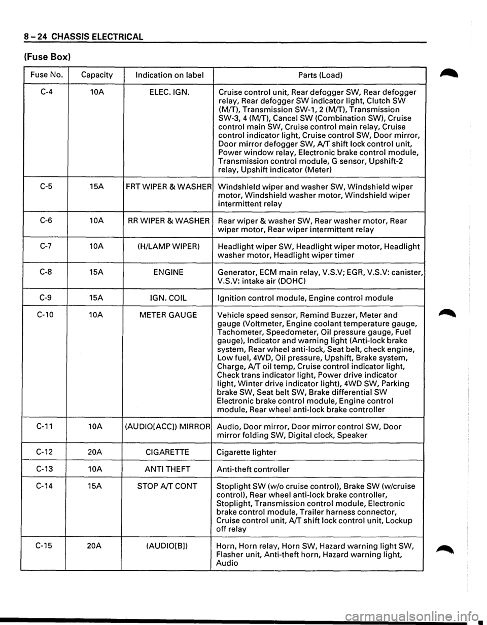
8-24 CHASSIS ELECTRICAL
(Fuse Box)
Fuse No.
Capacity Indication on label Parts (Load)
C-4 10A
ELEC.IGN. Cruise control unit, Rear defogger SW, Rear defogger
relay, Rear
defo9ger SW indicator light, Clutch SW
(M{T), Transmission SW-1, 2 (M!T), Transmission
SW-3, 4 (M{T), Cancel
SW (Combination SW), Cruise
control main
SW, Cruise control main relay, Cruise
control indicator light, Cruise control
SW, Door mirror,
Door mirror defogger SW, AfT shift lock control unit,
Power window relay, Electronic brake control module,
Transmission control module, G sensor, Upshift-2
relay, Upshift indicator (Meter)
C-5 15A FRTWIPER &WASHER
Windshield wipt~r and washer SW, Windshield wiper
motor, Windshit~ld washer motor, Windshield wiper
intermittent relay
C-6 10A RR WIPER & WASHER
Rear wiper & washer SW, Rear washer motor, Rear
wiper motor, Rear wiper intermittent relay
C-7 10A (H/LAMP WIPER) Headlight wiper SW, Headlight wiper motor, Headlight
washer motor, Headlight
wiper timer
C-8 15A ENGINE Generator, ECM main relay, V.S.V; EGA, V.S.V: canister,
V.S.V: intake air
(DOHC)
C-9 15A IGN. COIL Ignition control module, Engine control module
C-10 10A METER GAUGE Vehicle speed stmsor, Remind Buzzer, Meter and
gauge
(Voltmeter, Engine coolant temperature gauge,
Tachometer, Speedometer,
Oil pressure gauge, Fuel
gauge),
Indicator and warning light (Anti-lock brake
system, Rear wheel anti-lock, Seat belt, check engine,
Low fuel, 4WD,
Oil pressure, Upshift, Brake system,
Charge,
AfT oil temp, Cruise control indicator light,
Check trans indicator light,
Power drive indicator
light,
Winter drive indicator light), 4WD SW, Parking
brake SW, Seat belt SW, Brake differential SW
Electronic brake control module, Engine control
module, Rear wheel anti-lock brake controller
C-11 10A (AUDIO[ACCJ) MIRROR Audio, Door mirror, Door mirror control SW, Door
mirror folding SW, Digital clock, Speaker
C-12 20A CIGARETTE Cigarette lighter
C-13 10A
ANTI THEFT Anti-theft controller
C-14 15A
STOP AfT CONT Stoplight SW (w/o cruise control), Brake SW (w/cruise
control), Rear wheel anti-lock brake controller,
Stoplight, Transmission control module, Electronic
brake control module, Trailer harness connector,
Cruise control unit,
AfT shift lock control unit, Lockup
off relay
C-15
20A (AUDIO[B]) Horn,
Horn relay, Horn SW, Hazard warning light SW,
Flasher unit, Anti-theft horn, Hazard warning light,
Audio
•
Page 1215 of 1928
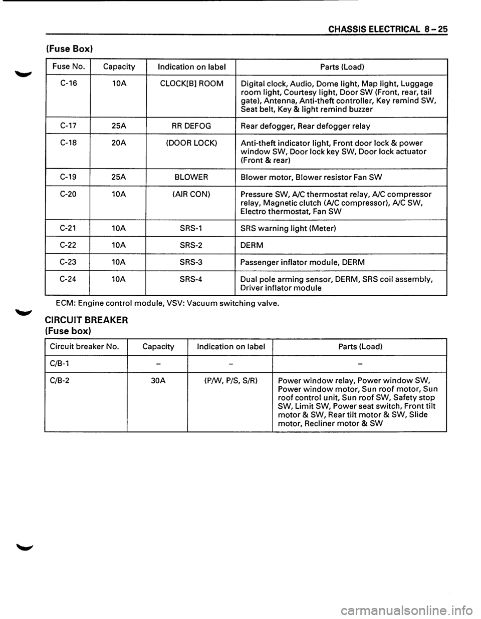
CHASSIS ELECTRICAL 8-25
(fuse Box)
Fuse No.
Capacity Indication on label Parts
(Load)
C-16
10A
CLOCK[B] ROOM Digital clock, Audio, Dome light, Map light, Luggage
room light, Courtesy light, Door SW (Front, rear, tail
gate), Antenna, Anti-theft controller, Key remind SW,
Seat belt, Key & light remind buzzer
C-17 25A RR DEFOG Rear defogger, Rear defogger relay
C-18 20A (DOOR LOCK) Anti-theft indicator light, Front door lock & power
window SW, Door lock key SW, Door lock actuator
(Front
& rear)
C-19 25A BLOWER Blower motor, Blower resistor Fan SW
C-20 10A (AIR CON) Pressure SW, A/C thermostat relay, A/C compressor
relay, Magnetic clutch
(A/C compressor), A/C SW,
Electro thermostat, Fan SW
C-21 10A SRS-1 SRS warning light (Meter)
C-22 10A SRS-2 DERM
C-23
10A SRS-3 Passenger inflator module, DERM
C-24
10A SRS-4 Dual pole arming sensor, DERM, SRS coil assembly,
Driver inflator module
ECM: Engine control module, VSV: Vacuum switching valve.
CIRCUIT BREAKER
(fuse box)
Circuit breaker No.
C/B-1
C/B-2
Capacity
-
30A
Indication on label
-
(P/W, P/S, S/R)
Parts (Load)
-
Power window relay, Power window SW,
Power window motor, Sun roof motor, Sun
roof control unit, Sun roof SW, Safety stop
SW, Limit SW, Power seat switch, Front tilt
motor & SW, Rear tilt motor & SW, Slide
motor, Recliner
motor & SW