oil temperature ISUZU TROOPER 1995 Service Manual
[x] Cancel search | Manufacturer: ISUZU, Model Year: 1995, Model line: TROOPER, Model: ISUZU TROOPER 1995Pages: 1928
Page 913 of 1928
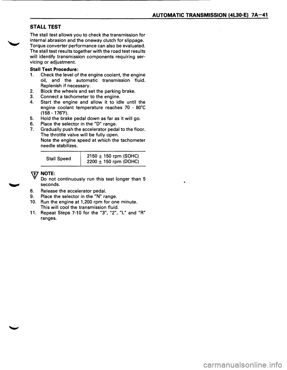
STALL TEST
The stall test allows you to check the transmission for
internal abrasion and the oneway clutch for slippage.
Torque converter performance can also be evaluated.
The
stall test results together with the road test results
will identify transmission components requiring ser
vicing or adjustment.
Stall Test Procedure:
1. Check the level of the engine coolant, the engine
oil, and the automatic transmission fluid.
Replenish
if necessary.
2. Block the wheels and set the parking brake.
3. Connect a tachometer to the engine.
4. Start the engine and allow it to idle until the
engine coolant temperature reaches
70 -8o·c
(158 -176.F).
5. Hold the brake pedal down as far as it will go.
6. Place the selector in the "D" range.
7. Gradually push the accelerator pedal to the floor.
The throttle valve
will be fully open.
Note the engine speed at which the tachometer
needle stabilizes.
Stall Speed
\fl NOTE:
2150 ± 150 rpm (SOHC)
2200 ± 150 rpm (DOHC)
VI Do not continuously run this test longer than 5
........, seconds.
8. Release the accelerator pedal.
9. Place the selector in the "N" range.
10. Run the engine at 1,200 rpm for one minute.
This
will cool the transmission fluid.
11. Repeat Steps 7-10 for the "3", "2", "L" and "R"
ranges.
AUTOMATIC TRANSMISSION (4L30-E) 7A-41
Page 914 of 1928
7 A-42 AUTOMATIC TRANSMISSION (4L30-E)
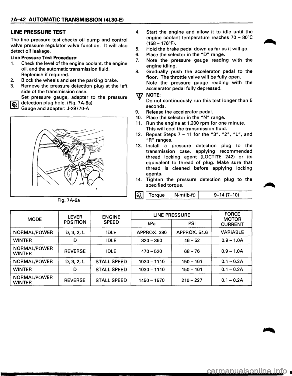
LINE PRESSURE TEST
The line pressure test checks oil pump and control
valve
pressure regulator valve function. It will also
detect oil leakage.
Line Pressure Test Procedure:
1. Check the level of the engine coolant, the engine
oil, and the automatic transmission fluid.
Replenish
if required.
2. Block the wheels and set the parking brake.
3. Remove the pressure detection plug at the left
side of the transmission case.
Set pressure gauge, adapter
to the pressure
l"iC\1 detection plug hole. (Fig. 7 A-6a)
~ Gauge and adapter: J-29770-A
Fig. 7A-6a
LEVER ENGINE
MODE
POSITION
SPEED
NORMAL/POWER D,3,2, L IDLE
WINTER D IDLE
NORMAL/POWER REVERSE IDLE WINTER
NORMAL/POWER
D,3,2,L STALL SPEED
WINTER D STALL SPEED
NORMAL/POWER REVERSE STALL SPEED WINTER
4.
5.
6.
7.
8.
9.
10.
11.
Start the engine and allow it to idle until the
engine
coolant temperature reaches 70 -80°C
(158-176°F).
Hold
the brake pedal down as far as it will go.
Place the selector in the "D" range.
Note the pressure gauge reading
with the
engine
idling.
Gradually
push the accelerator pedal to the
floor. The throttle valve will be fully open.
Note the pressure gauge reading
with the
accelerator
pedal fully depressed.
NOTE:
Do not continuously run this test longer than 5
seconds.
Release the accelerator pedal.
Place
the selector in the "N" range.
Run the engine at
1,200 rpm for one minute.
This
will cool the transmission fluid.
12. Repeat Steps 7-11 for the "3", "2", "L", and
"R" ranges.
13.
Install a pressure detection plug to the
transmission case,
applying recommended
thread
locking agent (LOCTITE 242) or its
equivalent to thread
of plug. Make sure that
thread is cleaned before applying locking
agents.
14. Tighten the pressure detection plug to the
specified torque.
~~~ Torque N·mOb·ft) / 9-14 (7-10)
LINE
PRESSURE FORCE
MOTOR kPa PSI CURRENT
APPROX. 380 APPROX. 54.6 VARIABLE
320-360 46-52 0.9 -1.0A
470-520 68-76 0.9 -1.0A
1030-1110 150-161 0.1-0.2A
1030-1110 150-161 0.1-0.2A
1450-1570 210-227 0.1-0.2A
•
Page 943 of 1928
AUTOMATIC TRANSMISSION (4L30-E) 7 A-71
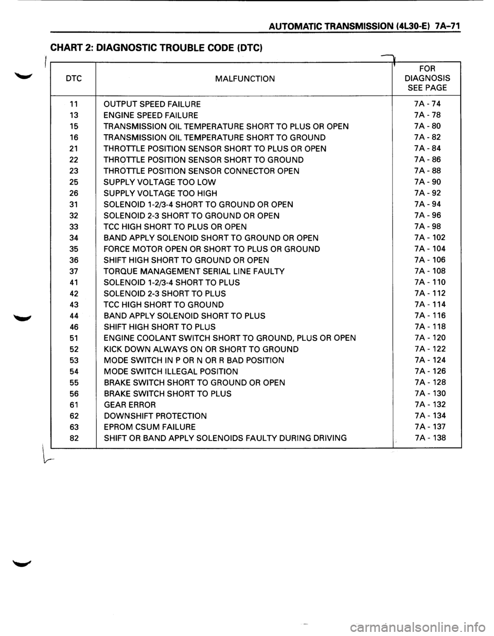
CHART 2: DIAGNOSTIC TROUBLE CODE (OTC)
I v
' FOR
DTC MALFUNCTION DIAGNOSIS
SEE PAGE
11 OUTPUT
SPEED FAILURE 7A -74
13 ENGINE SPEED FAILURE 7A -78
15 TRANSMISSION OIL TEMPERATURE SHORT TO PLUS OR OPEN 7A-80
16 TRANSMISSION OIL TEMPERATURE SHORT TO GROUND 7A-82
21 THROTTLE POSITION SENSOR SHORT TO PLUS OR OPEN 7A-84
22 THROTTLE POSITION SENSOR SHORT TO GROUND 7A-86
23 THROTTLE
POSITION SENSOR CONNECTOR OPEN 7A-88
25
SUPPLY VOLTAGE TOO LOW 7A-90
26 SUPPLY VOLTAGE TOO HIGH 7A-92
31 SOLENOID 1-2/3-4 SHORT TO GROUND OR OPEN 7A-94
32
SOLENOID 2-3 SHORT TO GROUND OR OPEN 7A-96
33 TCC
HIGH SHORT TO PLUS OR OPEN 7A-98
34
BAND APPLY SOLENOID SHORT TO GROUND OR OPEN 7A-102
35 FORCE MOTOR OPEN OR SHORT TO PLUS OR GROUND 7A-104
36 SHIFT HIGH SHORT TO GROUND OR OPEN 7A-106
37 TORQUE MANAGEMENT SERIAL LINE FAULTY 7A-108
41 SOLENOID 1-2/3-4 SHORT TO PLUS 7A-110
42 SOLENOID 2-3 SHORT TO PLUS 7A-112
43 TCC HIGH SHORT TO GROUND 7A-114
44
BAND APPLY SOLENOID SHORT TO PLUS 7A-116
46 SHIFT HIGH SHORT TO PLUS 7A-118
51 ENGINE COOLANT SWITCH SHORT TO GROUND, PLUS OR OPEN 7A-120
52 KICK DOWN ALWAYS ON OR SHORT TO GROUND 7A-122
53 MODE SWITCH IN P OR N OR R BAD POSITION 7A-124
54
MODE SWITCH ILLEGAL POSITION 7A-126
55 BRAKE
SWITCH SHORT TO GROUND OR OPEN 7A-128
56 BRAKE
SWITCH
SHORT TO PLUS 7A-130
61 GEAR ERROR 7A-132
62 DOWNSHIFT PROTECTION 7A-134
63
EPROM CSUM FAILURE 7A-137
82 SHIFT OR BAND APPLY SOLENOIDS FAULTY DURING DRIVING 7A-138
Page 952 of 1928
1 A-80 AUTOMATIC TRANSMISSION (4L30-E)
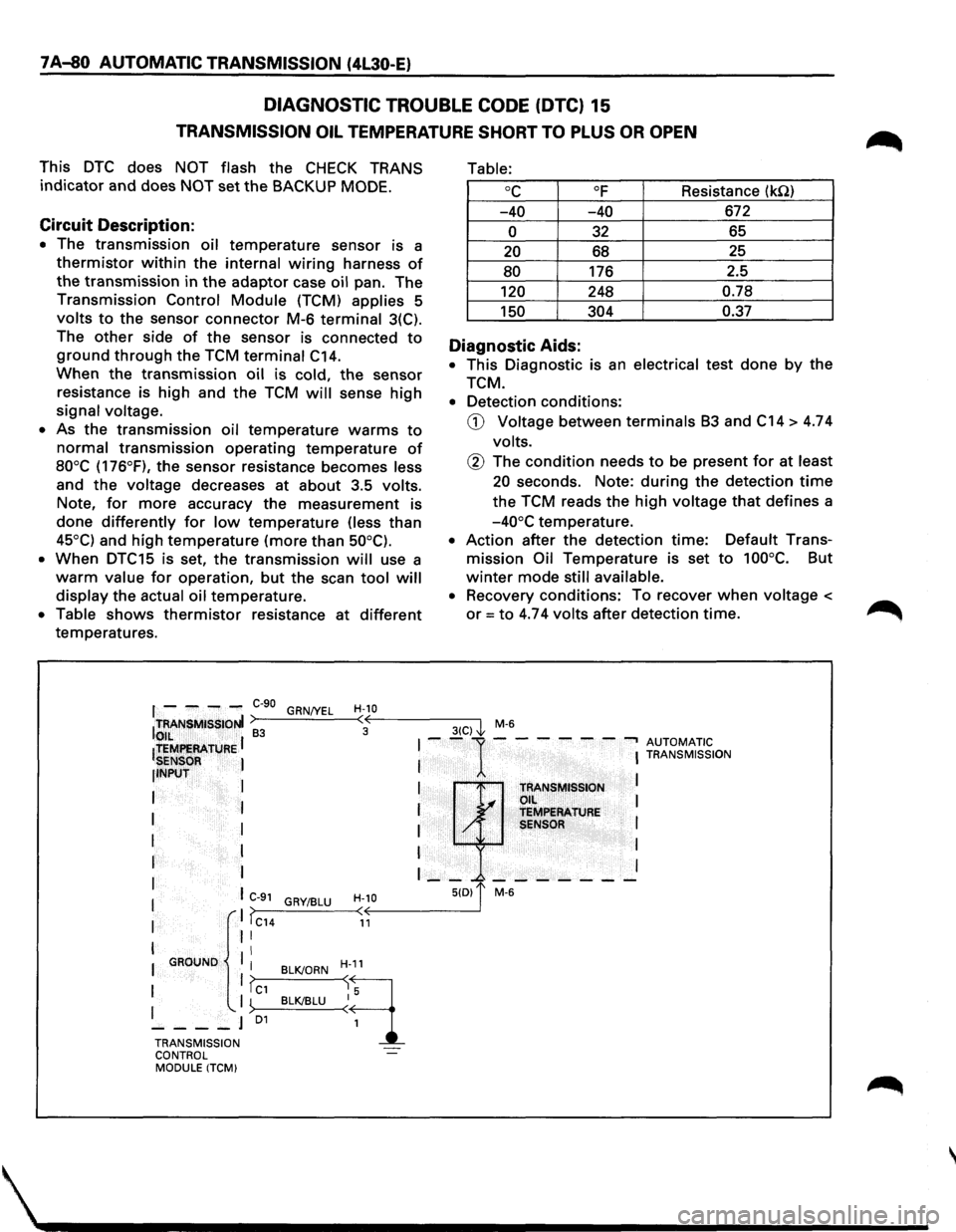
DIAGNOSTIC TROUBLE CODE (DTC) 15
TRANSMISSION OIL TEMPERATURE SHORT TO PLUS OR OPEN
This DTC does NOT flash the CHECK TRANS
indicator and does NOT set the BACKUP MODE.
Circuit Description:
• The transmission oil temperature sensor is a
thermistor within the internal wiring harness of
the transmission in the adaptor case oil pan. The
Transmission Control Module (TCM) applies 5
volts to the sensor connector M-6 terminal 3(C).
The
other side of the sensor is connected to
ground through the TCM terminal C14.
When the transmission oil is cold, the sensor
resistance is high and the TCM will sense high
signal voltage.
• As the transmission oil temperature warms to
normal transmission operating temperature of
80°C (176°F), the sensor resistance becomes less
and
the voltage decreases at about 3.5 volts.
Note,
for more accuracy the measurement is
done differently for low temperature (less than
45°C) and high temperature (more than 50°C).
•
When DTC15 is set, the transmission will use a
warm value for operation, but the scan tool will
display the actual oil temperature.
• Table shows thermistor resistance at different
temperatures.
Table:
oc OF Resistance (kQ)
-40 -40 672
0 32 65
20 68 25
80 176
2.5
120 248 0.78
150 304 0.37
Diagnostic Aids:
• This Diagnostic is an electrical test done by the
TCM.
• Detection conditions:
CD Voltage between terminals B3 and C14 > 4.74
volts.
@ The condition needs to be present for at least
20 seconds. Note: during the detection time
the TCM reads the high voltage that defines a
-40°C temperature.
• Action after the detection time: Default Trans
mission Oil Temperature is set to 100°C. But
winter mode still available.
• Recovery conditions: To recover when voltage <
or= to 4.74 volts after detection time.
f - ---C-90 GRN/YEL H-10 ITRANSMISSIONI >---'----<•((,--------3-(C--,) I M-6 to,,IL ~ 3 ~
ltEMf!EAATURE I I --1---- ---, AUTOMATIC
SENSOR I I I TRANSMISSION
llNPUT
I
I I
I TRANSMISSION L.... Oil I
I I I ~ TEMPERATURE
I I I / SENSOR I
I I I I
r I I __ _. _______ I
I I C-91 H-10 5(0) 1' M-6 GRY/BLU I ,. I >>---_:__--< < I IC14 11
I II
II I GROUND
I BLK/ORN H-11
1 1?c1 ~q I '-. I ~>--B_L__cKI_BL_U--<~ 5
----J 01
1
TRANSMISSION
CONTROL
MODULE ITCM)
Page 953 of 1928
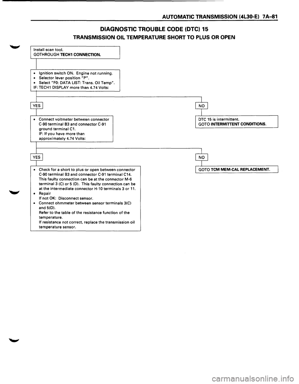
AUTOMATIC TRANSMISSION (4L30-E) 7 A-81
DIAGNOSTIC TROUBLE CODE (DTC) 15
TRANSMISSION OIL TEMPERATURE SHORT TO PLUS OR OPEN
Install scan tool.
GOTHROUGH
TECH1 CONNECTION.
• Ignition switch ON. Engine not running. • Selector lever position "P". • Select "FO: DATA LIST: Trans. Oil Temp". IF: TECH1 DISPLAY more than 4.74 Volts:
•
Connect voltmeter between connector C-90 terminal 83 and connector C-91 ground terminal C1.
IF: If you have more than approximately 4.74 Volts:
• Check
for a short to plus or open between connector C-90 terminal 83 and connector C-91 terminal C14. This faulty connection can be at the connector M-6 terminal 3 (C) or 5 (D). This faulty connection can be
at the intermediate connector
H-1 0 terminals 3 or 11. • Repair If not OK: Disconnect sensor.
• Connect ohmmeter between sensor terminals 3(C) and 5(D).
Refer
to the table of the resistance function of the
temperature.
If resistance not correct, replace the transmission oil temperature sensor.
DTC 15 is intermittent. GOTO INTERMITTENT CONDITIONS.
GOTO TCM MEM-CAL REPLACEMENT.
Page 954 of 1928
7 A-82 AUTOMATIC TRANSMISSION (4L30-E)
DIAGNOSTIC TROUBLE CODE (DTC) 16
TRANSMISSION OIL TEMPERATURE SHORT TO GROUND
This DTC does NOT flash the CHECK TRANS
indicator and does NOT set the BACKUP MODE.
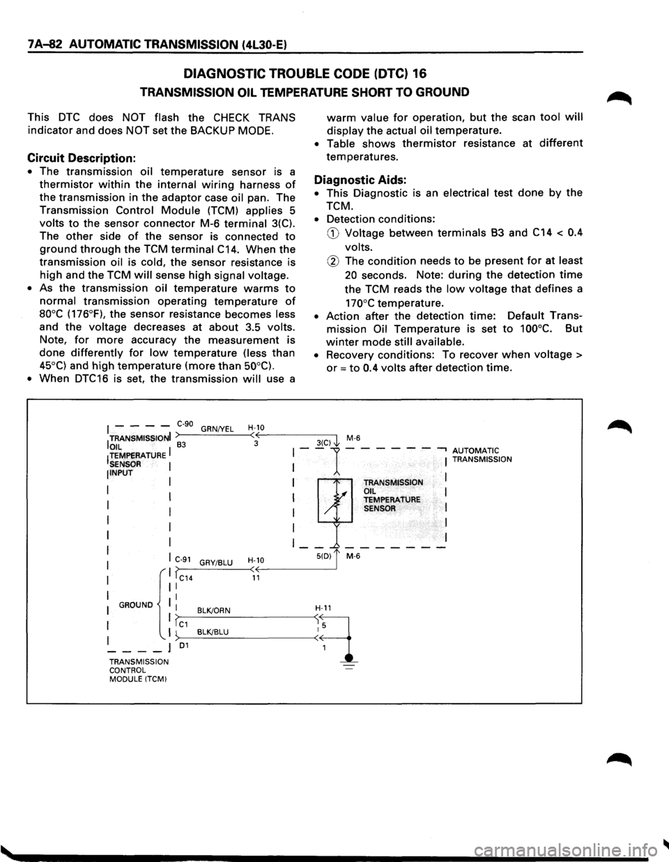
Circuit Description:
• The transmission oil temperature sensor is a
thermistor within the internal wiring harness of
the transmission in the adaptor case oil pan. The
Transmission Control Module (TCM) applies 5
volts to the sensor connector M-6 terminal 3(C).
The
other side of the sensor is connected to
ground through the TCM terminal C14. When the
transmission oil is cold, the sensor resistance is
high and the TCM will sense high signal voltage.
•
As the transmission oil temperature warms to
normal transmission operating temperature of
aooc (176°F), the sensor resistance becomes less
and the voltage decreases at about 3.5 volts.
Note, for more accuracy the measurement is
done differently for low temperature (less than
45°C) and high temperature (more than 50°C).
•
When DTC16 is set, the transmission will use a
warm value for operation, but the scan tool will
display the actual oil temperature.
• Table shows thermistor resistance at different
temperatures.
Diagnostic Aids:
• This Diagnostic is an electrical test done by the
TCM.
• Detection conditions:
G) Voltage between terminals B3 and C14 < 0.4
volts.
@ The condition needs to be present for at least
20 seconds. Note: during the detection time
the TCM reads the low voltage that defines a
170°C temperature.
• Action after the detection time: Default Trans
mission Oil Temperature is set to 100°C. But
winter mode still available.
•
Recovery conditions: To recover when voltage >
or = to 0.4 volts after detection time.
I - - - -e-go GRN/YEL H-10
ITRANSMISSIONI >----'-----<:·oE---------3-(C-)-,'1 M-6
OIL I 83 I--1-- --- -.., AUTOMATIC !TEMPERATURE I I TRANSMISSION SENSOR NPUT I TRANSMISSION I .I OIL I I y TEMPERATURE I / SENSOR I
I
I I
I __ _.-------
C>--9_1_G_RY_I_BL_U_-
TRANSMISSION ~·· ... -l
CONTROL MODULE !TCM)
Page 955 of 1928
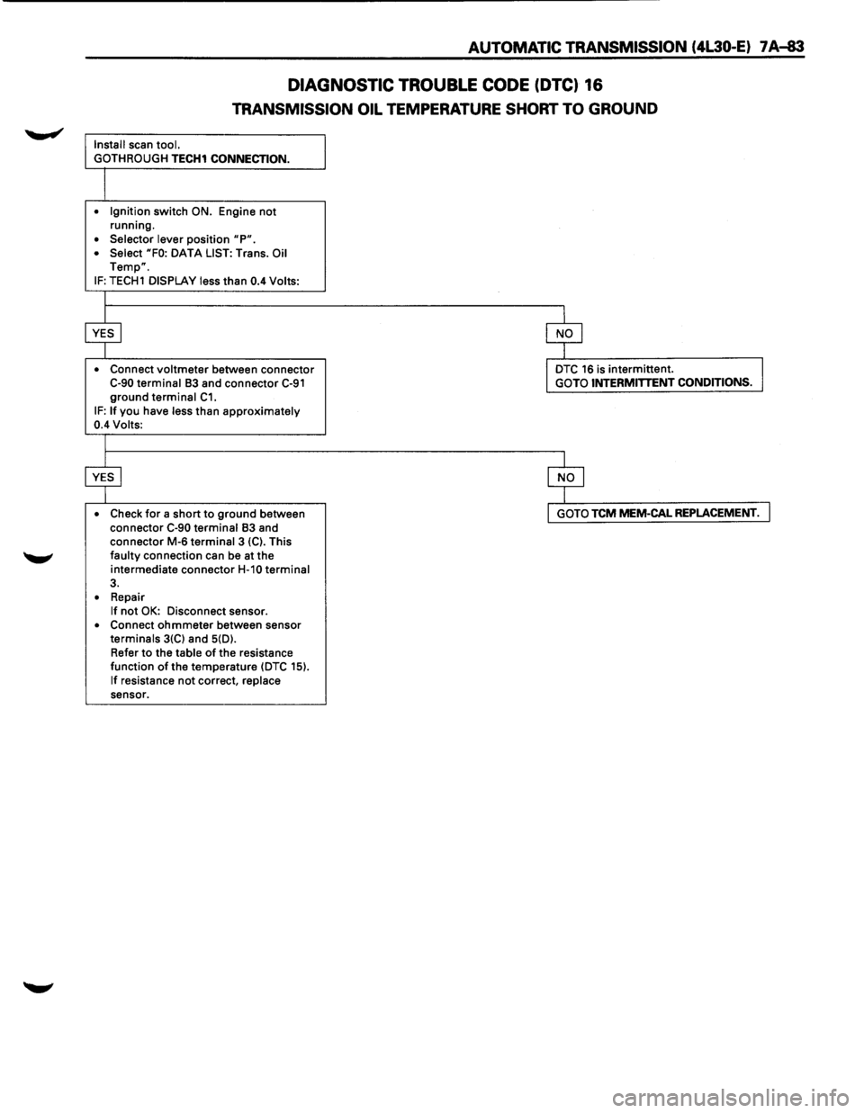
AUTOMATIC TRANSMISSION (4L30-E) 7 A-83
DIAGNOSTIC TROUBLE CODE (DTC) 16
TRANSMISSION OIL TEMPERATURE SHORT TO GROUND
Install scan tool.
GOTH ROUGH
TECH1 CONNECTION.
• Ignition switch ON. Engine not running.
• Selector lever position "P". • Select "FO: DATA LIST: Trans. Oil Temp".
IF: TECH1 DISPLAY less than 0.4 Volts:
• Connect
voltmeter between connector C-90 terminal 83 and connector C-91 ground terminal C1. IF: If you have less than approximately 0.4 Volts:
• Check
for a short to ground between
connector C-90 terminal 83 and
connector M-6 terminal 3 {C). This faulty connection can be at the
intermediate connector
H-10 terminal 3.
• Repair If not OK: Disconnect sensor. • Connect ohmmeter between sensor terminals 3{C) and 5{D).
Refer
to the table of the resistance
function of the temperature {DTC 15).
If resistance not correct, replace sensor.
DTC 16 is intermittent. GOTO INTERMITTENT CONDITIONS.
GOTO TCM MEM-CAL REPLACEMENT.
Page 962 of 1928
7 A-90 AUTOMATIC TRANSMISSION (4L30-E)
DIAGNOSTIC TROUBLE CODE (DTC) 25
SUPPLY VOLTAGE TOO LOW
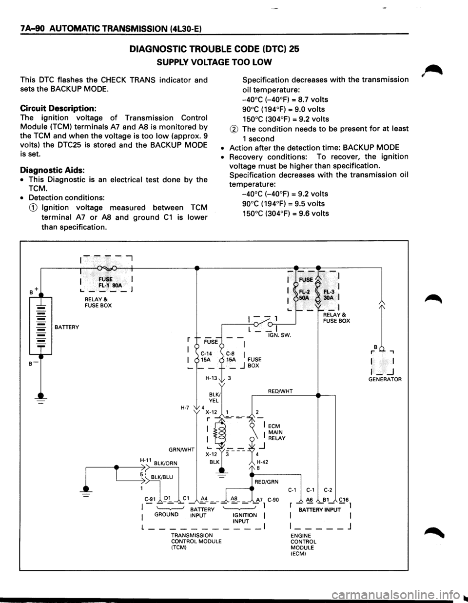
This DTC flashes the CHECK TRANS indicator and
sets the BACKUP
MODE.
Specification decreases with the transmission
oil temperature:
Circuit Description:
-40°C (-40°F) = S.7 volts
90°C (194°F) = 9.0 volts
150°C (304°F) = 9.2 volts The ignition voltage of Transmission Control
Module (TCM) terminals A7 and AS is monitored by
the TCM and when the voltage is too low (approx. 9
volts) the DTC25 is stored and the BACKUP MODE
is set.
@ The condition needs to be present for at least
1 second
• Action after the detection time: BACKUP MODE
Diagnostic Aids:
• This Diagnostic is an electrical test done by the
TCM.
• Recovery conditions: To recover, the ignition
voltage must be higher than specification.
Specification decreases
with the transmission oil
temperature:
-40°C (-40°F) = 9.2 volts
90°C (194°F) = 9.5 volts
150°C (304°F) = 9.6 volts
• Detection conditions:
CD Ignition voltage measured between TCM
terminal A7 or AS and ground C1 is lower
than specification .
. · fU I
I '
f:L;~soA L., ____ J
RELAY & FUSE BOX
1--, {)-:,.--____..J BATTERY
l
T
L __ I
r
I C-14 C-8 I I 15A 15A FUSE -__ + _ j BOX
H-13t 3
H-7 'x~.~~'---7 r ]_-
GRN/WHT
BATTERY I GROUND INPUT IGNITION I INPUT I
L-----------TRANSMISSION
CONTROL MODULE
(TCM) IGN.SW.
RED/WHT
C-1 C-1 C-2
A6 B1 C16
r -;ATTERV INPUT-l
I
I l _____ j
ENGINE
CONTROL MODULE
(ECM)
I I
I-_j GENERATOR
Page 992 of 1928
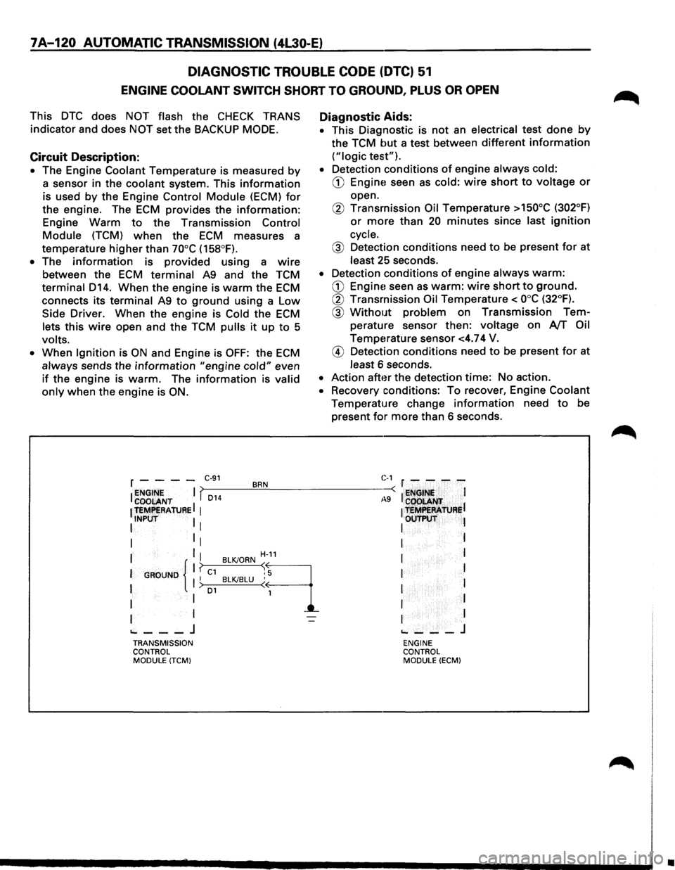
7A-120 AUTOMATIC TRANSMISSION (4L30-E)
DIAGNOSTIC
TROUBLE CODE (DTC) 51
ENGINE COOLANT SWITCH SHORT TO GROUND, PLUS OR OPEN
This DTC does NOT flash the CHECK TRANS
indicator and does NOT set the BACKUP MODE.
Circuit Description:
• The Engine Coolant Temperature is measured by
a sensor in the coolant system. This information
is used by the Engine Control Module (ECM) for
the engine. The ECM provides the information:
Engine Warm to the Transmission Control
Module (TCM) when the ECM measures a
temperature
higher than 70°C (158°F).
• The information is provided using a wire
between the ECM terminal A9 and the TCM
terminal D14. When the engine is warm the ECM
connects its terminal A9 to ground using a Low
Side Driver. When the engine is Cold the ECM
lets this wire open and the TCM pulls it up to 5
volts.
•
When Ignition is ON and Engine is OFF: the ECM
always sends the information "engine cold" even
if the engine is warm. The information is valid
only when the engine is ON.
Diagnostic Aids:
• This Diagnostic is not an electrical test done by
the TCM but a test between different information
("logic test").
• Detection conditions of engine always cold:
CD Engine! seen as cold: wire short to voltage or
open.
@ Transmission Oil Temperature >150°C (302°F)
or more than 20 minutes since last ignition
cycle.
@ Detection conditions need to be present for at
least 25 seconds.
• Detection conditions of engine always warm:
CD Engine! seen as warm: wire short to ground.
@ Transmission Oil Temperature< ooc (32°F).
@ Without problem on Transmission Tem
perature sensor then:
voltage on AfT Oil
Temperature sensor <4.74 V.
@ Detection conditions need to be present for at
least 6 seconds.
• Action after the detection time: No action.
• Recovery conditions: To recover, Engine Coolant
Temperature change information need to be
present
for more than 6 seconds.
r - - - -C·91 BRN C-1 r - - - -
I ~~~ENT I f,_D_1_4 __ ~.!__--------~-: I ~NGt~~ I
1 teMPERAtuRE I 1
1 t=R'ATJJRel
I INPUT I I I OUTP\:IT l
I 1
1 I I
I I I H-11 I l
I
GROUND 11 ? C1 BLKJORN ~9 I I I I BLKJBLU ( 1 I > o1 I
I I 1 I I
I I I I
~---J ~---J TRANSMISSION ENGINE
CONTROL CONTROL
MODULE
(TCM) MODULE (ECM)
•
Page 1012 of 1928
7A-140 AUTOMATIC TRANSMISSION (4L30-E)
WITHOUT DTC SET
1. If you have already checked the Diagnostic
Trouble Code (DTC) and the scan tool TECH1
does not provide any DTC, and you have
reproduced the
problem and no DTC was
stored:
This means that you have
to check the problem
by comparing the way it should work to the
way it works now that the problem exits.
2. To find the problem, perform the following
tests:
• A/TOil Temperature Indicator Test
• Transmission Operating Mode Test
•