check engine light ISUZU TROOPER 1995 Manual Online
[x] Cancel search | Manufacturer: ISUZU, Model Year: 1995, Model line: TROOPER, Model: ISUZU TROOPER 1995Pages: 1928
Page 1466 of 1928
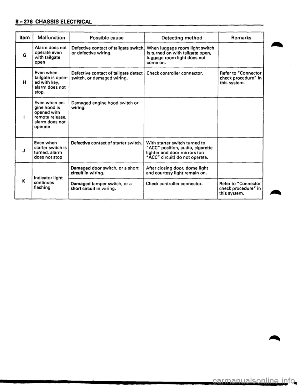
8-276 CHASSIS ELECTRICAL
Item Malfunction
Possible cause
Detecting method Remarks
Alarm
does not
Defective contact of tailgate switch When luggage room light switch
G operate even or defective wiring. is turned on with tailgate open, with tailgate
luggage room light does not open
come on.
Even when
Defective contact
of tailgate detect Check controller connector. Refer to "Connector tailgate is open-
switch, or damaged wiring.
check procedure" in H ed with key, this system.
alarm does not
stop.
Even when en-
Damaged engine hood switch or gine hood is wiring.
opened with
I remote release,
alarm does not
operate
Even when
Defective contact
of starter switch. With starter switch turned to
J starter switch is II ACC" position, audio, cigarette
turned, alarm
lighter and door mirrors (on
does not stop
II ACC" circuit) do not operate.
Damaged
door switch, or a short After closing door, dome light
circuit in wiring. and courtesy light remain on.
K Indicator light
continues Damaged tamper switch, or a
Check controller connector. Refer to "Connector flashing
short circuit in wiring. check
procedure" in
this system.
..
Page 1467 of 1928
------------- -
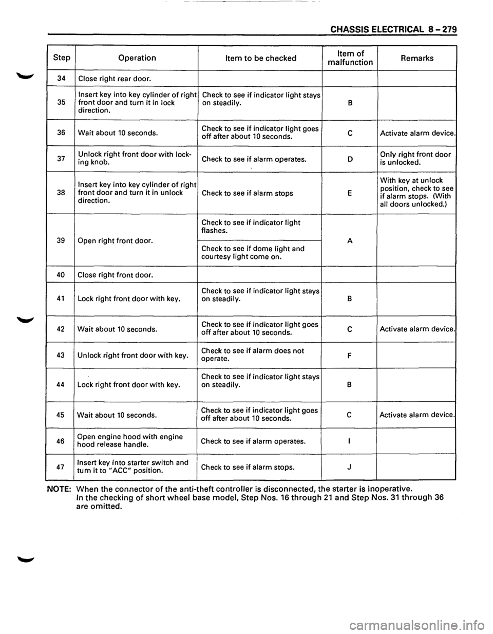
CHASSIS ELECTRICAL 8-279
Step Operation Item to be checked Item of Remarks
malfunction
34 Close right rear door.
Insert key into key cylinder of right
Check to see if indicator light stays 35 front door and turn it in lock on steadily. B direction.
36 Wait about 10 seconds. Check
to see if indicator light goes c Activate alarm device. off after about 10 seconds.
37 Unlock right front door with lock-Check to see if alarm operates. D Only right front door ing knob.
is unlocked.
Insert
key into key cylinder of right With
key at unlock
position, check to see 38 front door and turn it in unlock Check to see if alarm stops E if alarm stops. (With
direction.
all doors unlocked.)
Check to see if indicator light flashes.
39 Open right front door.
A
Check to
see if dome light and
courtesy light come on.
40 Close right front door.
Check to
see if indicator light stays 41 Lock right front door with key.
on steadily. B
42 Wait about 10 seconds. Check
to see if indicator light goes c Activate alarm device. off after about 10 seconds.
43 Unlock right front door with key. Check
to see if alarm does not F operate.
Check to
see if indicator light stays 44 Lock right front door with key.
on steadily. B
45 Wait about 10 seconds. Check
to see if indicator light goes c Activate alarm device. off after about 10 seconds.
46 Open engine hood with engine
Check to see if alarm operates. I hood release handle.
47 Insert key into starter switch and
Check to see if alarm stops. J turn it to "ACC" position.
NOTE: When the connector of the anti-theft controller is disconnected, the starter is inoperative.
In the checking of short wheel base model, Step Nos. 16 through 21 and Step Nos. 31 through 36
are omitted.
Page 1469 of 1928
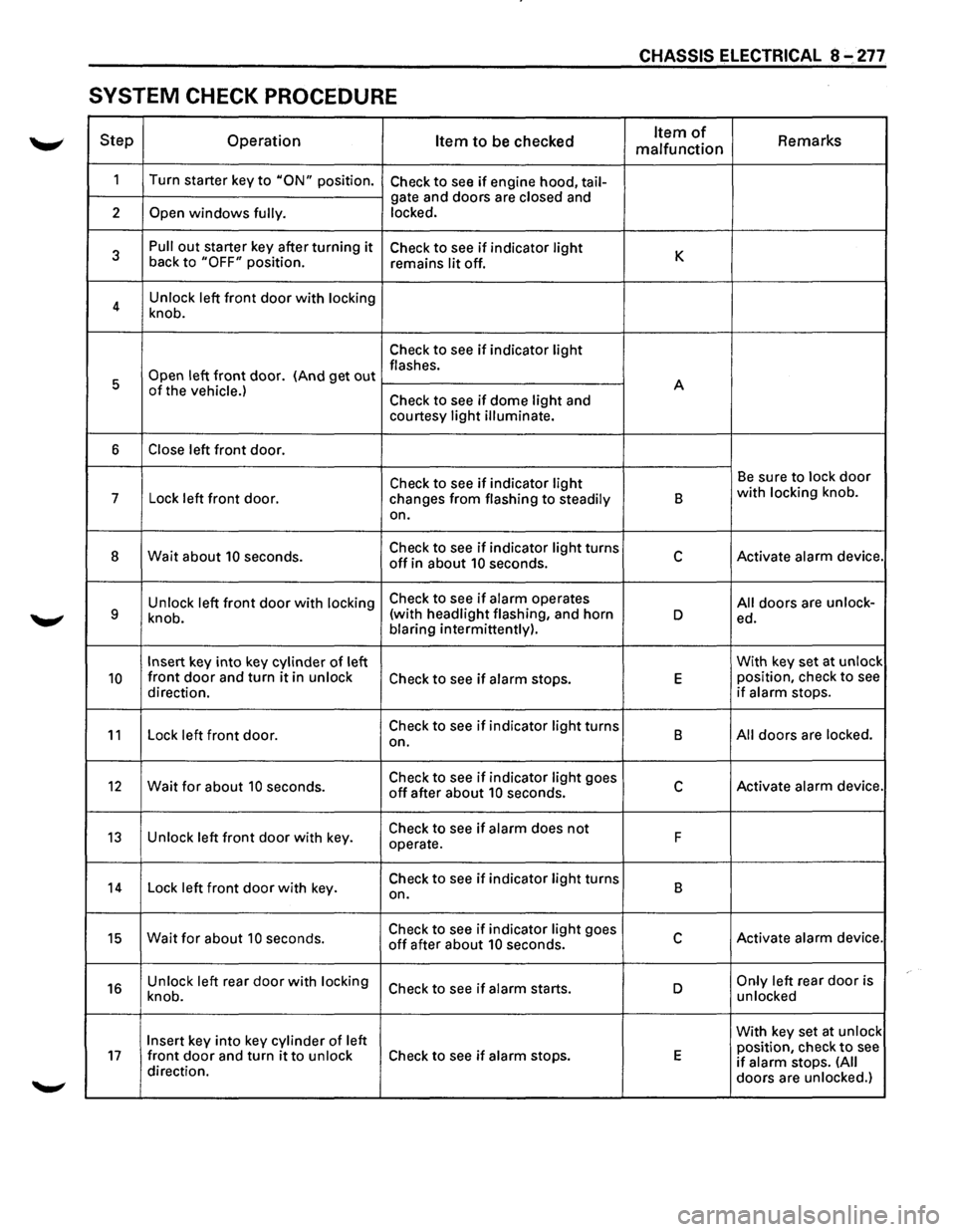
CHASSIS ELECTRICAL 8 ~ 277
SYSTEM CHECK PROCEDURE
Step Operation Item to be checked Item of Remarks malfunction
1
Turn starter key to "ON" position. Check to see if engine hood, tail-
gate and doors are closed and
2
Open windows fully. locked.
3
Pull out starter key after turning it Check to see if indicator light K back to "OFF" position.
remains lit off.
4 Unlock
left
front door with locking
knob.
Check to see if indicator light
Open left front door. (And get out flashes.
5 A
of the vehicle.) Check to see if dome light and
courtesy light illuminate.
6 Close left front door.
Check to see if indicator light Be sure to lock door
7
Lock left front door.
changes from flashing to steadily B with locking knob.
on.
8 Wait about 10 seconds. Check to see if indicator light turns c Activate alarm device. off in about 10 seconds.
Unlock left
front door with locking Check to see if alarm operates All doors are unlock-9 knob. (with
headlight flashing, and horn D ed.
blaring intermittently).
Insert key into key cylinder of left With
key set at unlock
10 front door and turn it in unlock Check to see if alarm stops. E position, check to see
direction. if alarm stops.
11 Lock left front door. Check to see if indicator light turns
B All doors are locked.
on.
12 Wait for about 10 seconds. Check to see if indicator light goes c Activate alarm device. off after about 10 seconds.
13 Unlock left front door with key. Check to see if alarm does not F
operate.
14 Lock left front door with key. Check to see if indicator light turns
B
on.
15 Wait for about 10 seconds. Check to see if indicator light goes c Activate alarm device. off after about 10 seconds.
16 Unlock left rear door with locking Check to see if alarm starts. D Only left rear door is
knob. unlocked
Insert key
into key cylinder of left With
key set at unlock
position, check to see 17 front door and turn it to unlock Check to see if alarm stops. E if alarm stops. (All direction.
doors are unlocked.)
Page 1485 of 1928
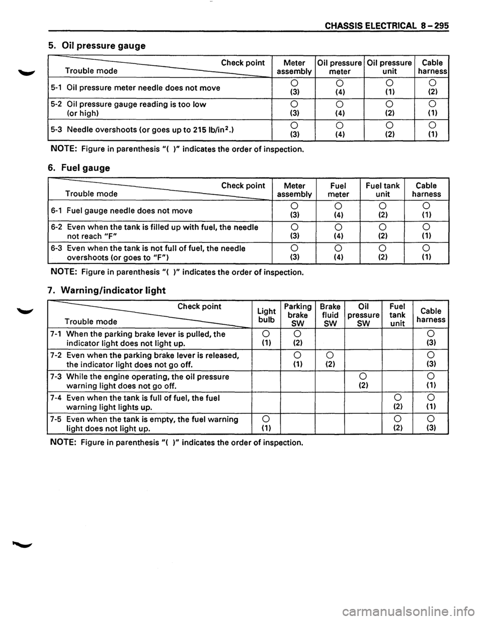
CHASSIS ELECTRICAL 8-295
5. Oil pressure gauge
Check point Meter Oil pressure Oil pressure Cable
Trouble mode
assembly meter unit harness
5-1 Oil pressure meter needle does not move 0
0 0
0 (3) (4) (1) (2)
5-2 Oil pressure
gauge reading is too low 0
0 0
0
(or
high) (3) (4) (2) (1)
5-3 Needle overshoots
(or goes up to 2151b/in2.) 0
0 0 0 (3) (4) (2)
(1)
NOTE: Figure
in parenthesis "( )" indicates the order of inspection.
6. Fuel gauge
Check point Meter Fuel Fuel tank Cable
Trouble mode assembly
meter unit harness
6-1 Fuel gauge needle does not move 0
0 0 0 (3) (4) (2) (1)
6-2 Even when the tank is filled up with fuel, the needle 0
0 0
0
not reach "F" (3) (4) (2)
(1)
6-3
Even when the tank is not full of fuel, the needle 0
0 0
0
overshoots (or goes to "F") (3) (4) (2) (1)
NOTE: Figure
in parenthesis "( )" indicates the order of inspection.
7. Warning/indicator light
~
Light Parking
Brake Oil Fuel Cable brake fluid pressure tank bulb sw sw sw unit harness
e
7-1 When the parking brake lever is pulled, the 0 0 0
indicator light does not light up. (1) (2) (3)
7-2 Even
when the parking brake lever is released, 0 0 0
the indicator light does not go off. (1) (2) (3)
7-3 While the engine operating,
the oil pressure 0 0
warning light does not go
off. (2)
(1)
7-4 Even
when the tank is full of fuel, the fuel 0 0
warning light lights
up. (2) (1)
7-5 Even
when the tank is empty, the fuel warning 0 0
0
light does not light up. (1) (2)
(3)
NOTE: Figure in parenthesis "( )" indicates the order of inspection.
Page 1507 of 1928
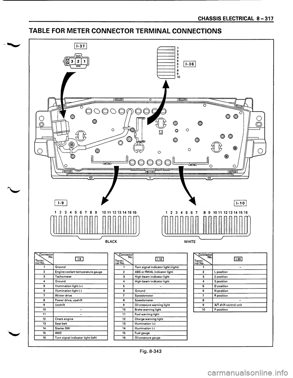
CHASSIS ELECTRICAL 8-317
TABLE FOR METER CONNECTOR TERMINAL CONNECTIONS
~-""""""', 1----""'12 1----""'1! 6 1----l 6 [Iill
1----""'1 ~ 9 1---""'l,o
®
0 0
0
® @
0 0 ~
~m© © © © ©'--m ~~0
0 !III
1 2 3 4 5 6 7 8 9 1011 1213141516 1 2 3 4 56 7 8 9 10111213141516
w~~~~~~~~ ~~~~~~m rn~~~~~~ ~~nn~~m
~ I J BLACK WHITE
~r o. DTI -na No. ~
. IJJ:Q] -
. ~ [ill] . -. 1 Ground 1 Turn
signal indicator light (right)
1 -2 Engine coolant temperature gauge 2 ABS or RWAL indicator light 2 L
position
3 Tachometer 3 High-beam indicator light 3 2 position 4
Ground
4 High-beam
indicator light 4 3 position 6 Illumination light (+I 5 -5 D position
6 Illumination light(-) 6 Ground 6 N position 7 Winter drive 7 Speedometer 7 R position 8 Power drive, upshift 8 Speedometer 8 -9 Upshift 9 Oil pressure warning light 9 AfT shift control unit 10 -10 Brake warning light 10 P position 11 -11 Fuel warning light 12 Check engine 12 Charge warning light 13 Seat belt 13 Illumination (+) 14 StarterSW 14 Illumination (-) 15 4WD 15 Fuel gauge 16 Turn signal indicator light (left) 16 Oil pressure gauge
Fig. 8-343
Page 1521 of 1928
![ISUZU TROOPER 1995 Manual Online OIL PRESSURE UNIT
(1!] INSPECTION
Measure the resistance value ofthe oil pressure unit
with the circuit tester. (Fig. 8-377)
Replace the
unit when the result of inspection is found
abnorm](/img/61/57183/w960_57183-1520.png "ISUZU TROOPER 1995 Manual Online OIL PRESSURE UNIT
(1!] INSPECTION
Measure the resistance value ofthe oil pressure unit
with the circuit tester. (Fig. 8-377)
Replace the
unit when the result of inspection is found
abnorm")
OIL PRESSURE UNIT
(1!] INSPECTION
Measure the resistance value ofthe oil pressure unit
with the circuit tester. (Fig. 8-377)
Replace the
unit when the result of inspection is found
abnormal.
Pressure
(kPa)
Resistance value (Q)
Fig. 8-377
OIL PRESSURE SWITCH
(1!] INSPECTION
98 981
81 30
I~~ Check the continuity between the switch termi
nal and the body ground with the engine at idle.
(Fig. 8-378)
Replace the switch when the result
of inspection
is
found abnormal.
Fig. 8-378
CHASSIS ELECTRICAL 8-331
(1!] CIRCUIT INSPECTION (FIG. 8-379)
Fig. 8-379
1. Start the engine.
2. When disconnecting the oil pressure switch con
nector then connecting the harness side connec
tor to the ground, check to see if the oil pressure
warning light lights up.
When the
light will not light up, check the circuit
between the meter and the oil pressure switch,
and repair
an open circuit if necessary.
FUEL TANK UNIT
The tank unit varies the internal resistance according
to the float position (fluid level) to operate the fuel
meter needle.
It is also designed
to warn the driver of low fuel level
by illuminating the fuel warning light. (Fig. 8-380)
Fig. 8-380
Page 1523 of 1928
1. Fuel tank
• Refer to fuel tank removal steps in Section 6C
"ENGINE FUEL."
2. Fuel tank unit
• Disconnect the connectors.
• Remove the five screws.
B INSTALLATION
To install, follow the removal steps in the reverse
order.
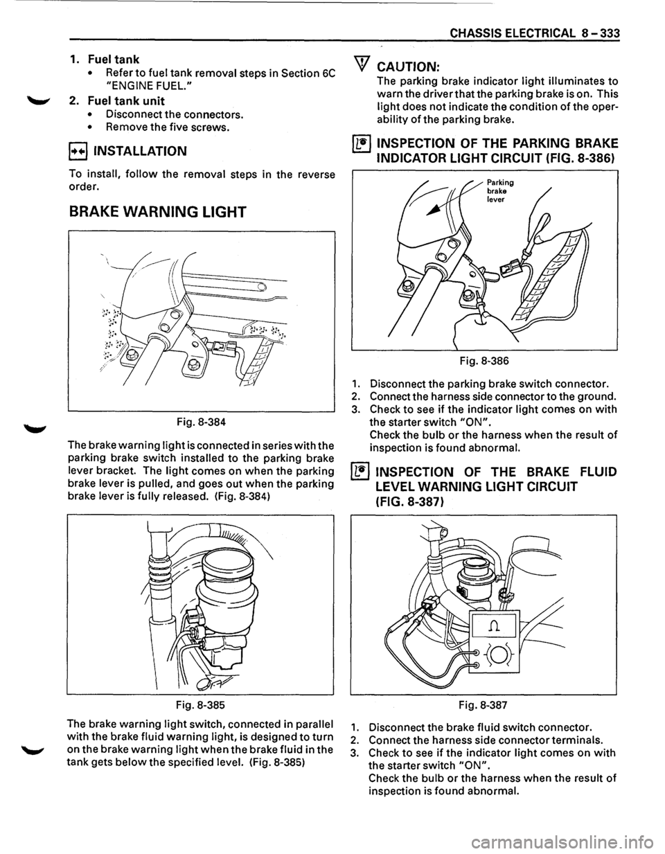
BRAKE WARNING LIGHT
Fig. 8-384
The brake
warning light is connected in series with the
parking brake switch
installed to the parking brake
lever bracket. The
light comes on when the parking
brake lever is
pulled, and goes out when the parking
brake lever is
fully released. (Fig. 8-384)
Fig. 8-385
The brake warning
light switch, connected in parallel
with the brake fluid warning light, is designed to turn
on the brake warning light when the brake fluid in the
tank gets
below the specified level. (Fig. 8-385)
CHASSIS ELECTRICAL 8-333
"f CAUTION:
The parking brake indicator light illuminates to
warn the driver that the parking brake is on. This
light does not indicate the condition of the oper
ability of the parking brake.
~ INSPECTION OF THE PARKING BRAKE
INDICATOR LIGHT CIRCUIT (FIG. 8-386)
Fig. 8-386
1. Disconnect the parking brake switch connector.
2. Connect the harness side connector to the ground.
3. Check to see if the indicator light comes on with
the starter switch "ON".
Check the bulb or the harness when the result of
inspection is found abnormal.
~ INSPECTION OF THE BRAKE FLUID
LEVEL WARNING LIGHT CIRCUIT
(FIG.
8-387)
Fig. 8-387
1. Disconnect the brake fluid switch connector.
2. Connect the harness side connector terminals.
3. Check to see if the indicator light comes on with
the starter switch "ON".
Check the bulb or the harness when the result of
inspection is found abnormal.
Page 1614 of 1928
9B-30 CRUISE CONTROL
1. Front console assembly
• Remove four screws.
• Remove the transmission shift lever knob.
• Remove the transfer shift lever knob.
• Disconnect the seat heater switch connectors
(If so equipped).
• Disconnect the "POWER & WINTER" switch
connectors (A/T only).
2. Lower cluster assembly
• Remove three screws.
• Disconnect the cigar lighter connectors.
• Remove the cigar lighter illumination bulb
socket.
• Disconnect the ashtray illumination bulb
connector.
3. Instrument panel driver lower cover
• Remove the engine hood opener.
• Remove three screws and clip.
•
Disconnect four fasteners.
4. Steering cowl
• Remove seven screws.
5. Starter switch
• Disconnect the connector.
• Remove the screw.
8 INSTALLATION
To install, follow the removal steps in the reverse
order noting the following point.
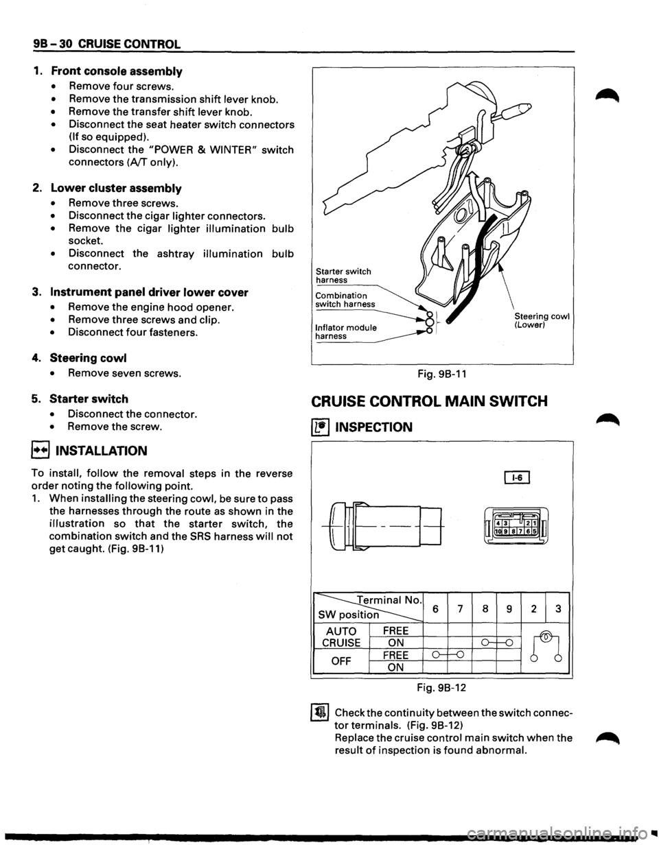
1. When installing the steering cowl, be sure to pass
the harnesses
through the route as shown in the
illustration so that the starter switch, the
combination switch and the SRS harness will not
get caught. (Fig. 98-11)
Starter switch
harness
Combination
switch harness
l._n!~~~o!_ module __..o .~ ~
Fig. 98-11
Steering cowl (Lower)
CRUISE CONTROL MAIN SWITCH
(1!1 INSPECTION
OI1
r-="'
-L
r= t-------uii4J~l "ltl1 u
l
1111ilr9Tsl7lels .,
:::o.,..o-
~ s 6 7 8 9 2 3
AUTO FREE
n
CRUISE ON ()-1---n
OFF FREE o-f--0
ON
Fig. 98-12
ltjl Check the continuity between the switch connec
tor terminals. (Fig. 98-12)
Replace the cruise control main switch when the ~
result of inspection is found abnormal.