check engine light ISUZU TROOPER 1995 Repair Manual
[x] Cancel search | Manufacturer: ISUZU, Model Year: 1995, Model line: TROOPER, Model: ISUZU TROOPER 1995Pages: 1928
Page 844 of 1928
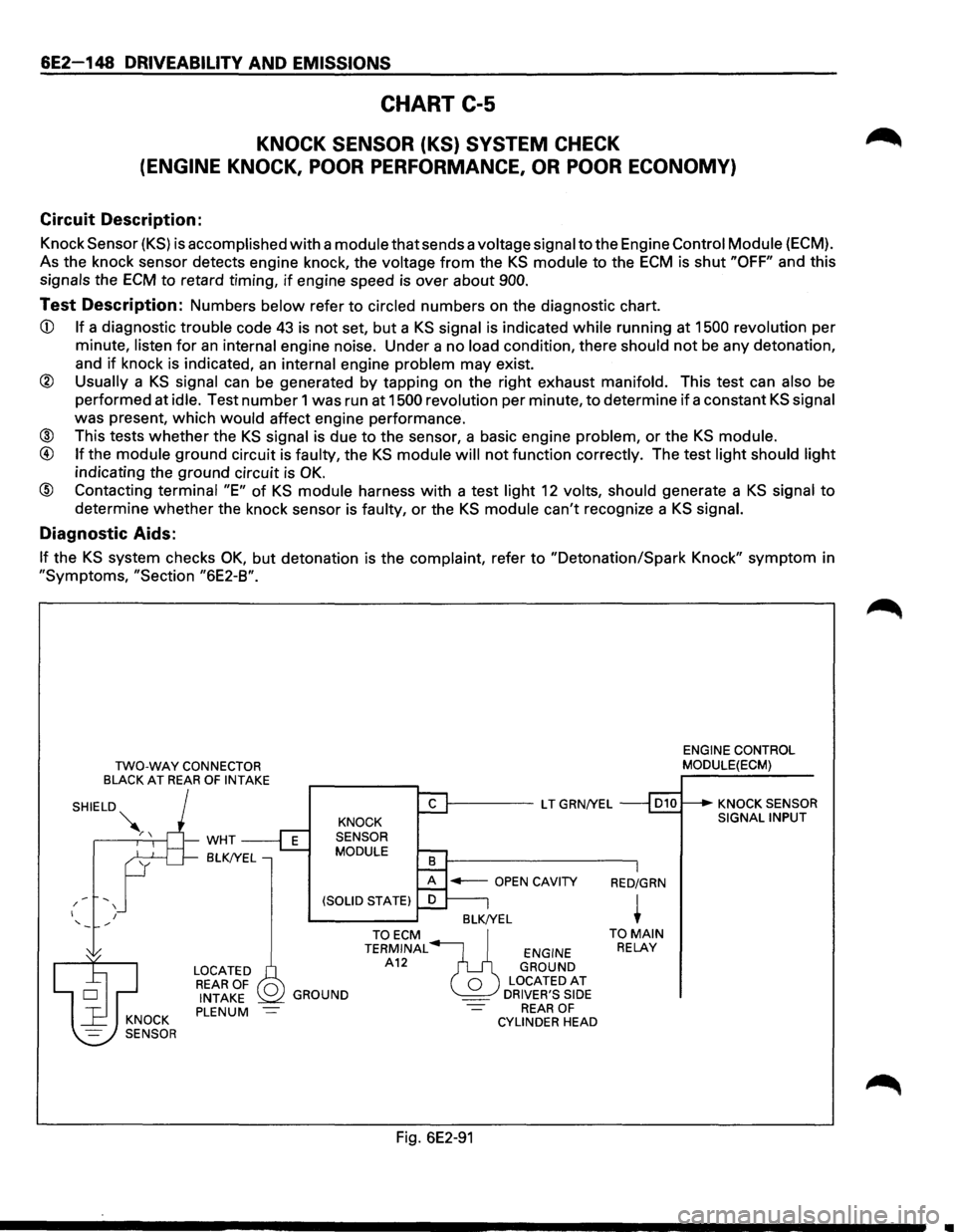
6E2-148 DRIVEABILITY AND EMISSIONS
CHART C-5
KNOCK SENSOR (KS) SYSTEM CHECK
(ENGINE KNOCK, POOR PERFORMANCE, OR POOR ECONOMY)
Circuit Description:
Knock Sensor (KS) is accomplished with a module that sends a voltage signal to the Engine Control Module {ECM).
As the knock sensor detects engine knock, the
voltage from the KS module to the ECM is shut "OFF" and this
signals the ECM to retard timing, if engine speed is over about 900.
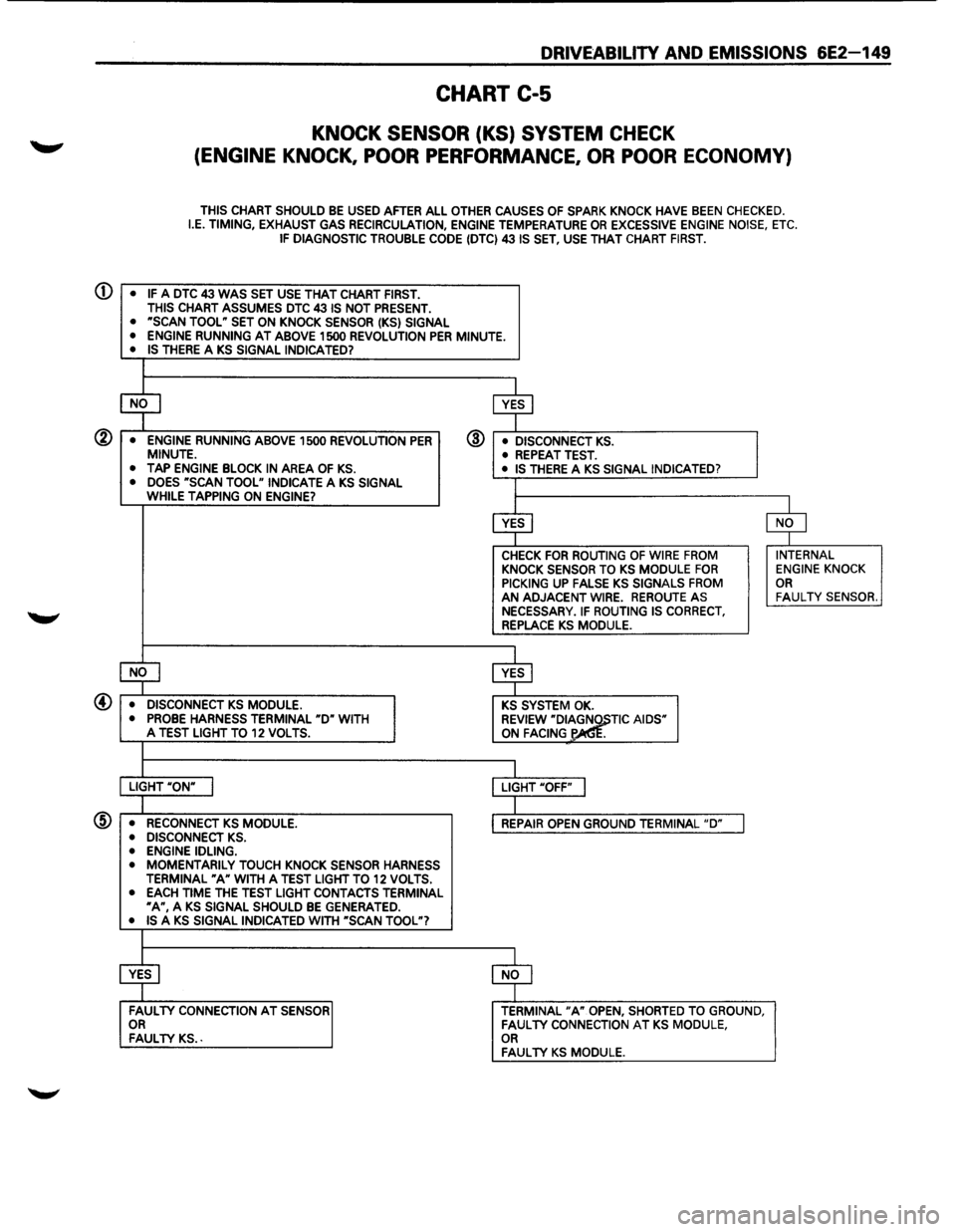
Test Description: Numbers below refer to circled numbers on the diagnostic chart.
CD If a diagnostic trouble code 43 is not set, but a KS signal is indicated while running at 1500 revolution per
minute,
listen for an internal engine noise. Under a no load condition, there should not be any detonation,
and
if knock is indicated, an internal engine problem may exist.
@ Usually a KS signal can be generated by tapping on the right exhaust manifold. This test can also be
performed at idle. Test number 1 was run at 1500 revolution per minute, to determine if a constant KS signal
was present, which would affect engine performance.
® This tests whether the KS signal is due to the sensor, a basic engine problem, or the KS module.
@ If the module ground circuit is faulty, the KS module will not function correctly. The test light should light
indicating the ground circuit is OK.
@ Contacting terminal "E" of KS module harness with a test light 12 volts, should generate a KS signal to
determine whether the knock sensor is faulty, or the KS module can't recognize a KS signal.
Diagnostic Aids:
If the KS system checks OK, but detonation is the complaint, refer to "Detonation/Spark Knock" symptom in
"Symptoms, "Section "6E2-8".
/ I
'
TWO-WAY CONNECTOR BLACK AT REAR OF INTAKE
I
-WHT
BLK!YEL
LOCATED REAR OF 0 INTAKE PLENUM
1------LT GRN/YEL
KNOCK
SENSOR
MODULE
BLK!YEL
GROUND
TOECM~ TERMINAL ENGINE A12 GROUND
0 LOCATEDAT _ DRIVER'S SIDE REAR OF CYLINDER HEAD
Fig. 6E2-91
RED/GRN
+ TO MAIN RELAY
ENGINE CONTROL
MODULE(ECM)
KNOCK SENSOR
SIGNAL INPUT
..
Page 845 of 1928
DRIVEABILITV AND EMISSIONS 6E2-149
CHART C-5
KNOCK SENSOR (KS) SYSTEM CHECK
(ENGINE KNOCK, POOR PERFORMANCE, OR POOR ECONOMY)
THIS CHART SHOULD BE USED AFTER ALL OTHER CAUSES OF SPARK KNOCK HAVE BEEN CHECKED. I.E. TIMING, EXHAUST GAS RECIRCULATION, ENGINE TEMPERATURE OR EXCESSIVE ENGINE NOISE, ETC. IF DIAGNOSTIC TROUBLE CODE (DTC) 431S SET, USE THAT CHART FIRST.
$ $
• ENGINE RUNNING ABOVE 1500 REVOLUTION PER @ • DISCONNECT KS. MINUTE. • REPEAT TEST. • TAP ENGINE BLOCK IN AREA OF KS. • IS THERE A KS SIGNAL INDICATED? • DOES ~scAN TOOL" INDICATE A KS SIGNAL I WHILE TAPPING ON ENGINE?
$ $
CHECK FOR ROUTING OF WIRE FROM INTERNAL KNOCK SENSOR TO KS MODULE FOR ENGINE KNOCK PICKING UP FALSE KS SIGNALS FROM OR AN ADJACENT WIRE. REROUTE AS FAUL TV SENSOR. NECESSARY. IF ROUTING IS CORRECT, REPLACE KS MODULE.
l4J $
• DISCONNECT KS MODULE. KS SYSTEM OK. • PROBE HARNESS TERMINAL "D" WITH REVIEW "DI~TIC AIDS" A TEST LIGHT TO 12 VOLTS. ON FACING .
I LIGHT "ON" I LIGHT "OFF" I
I • RECONNECT KS MODULE. REPAIR OPEN GROUND TERMINAL "D" J • DISCONNECT KS.
@
• ENGINE IDLING. • MOMENTARILY TOUCH KNOCK SENSOR HARNESS TERMINAL "A" WITH A TEST LIGHT TO 12 VOLTS. • EACH TIME THE TEST LIGHT CONTACTS TERMINAL ~A", A KS SIGNAL SHOULD BE GENERATED. • IS A KS SIGNAL INDICATED WITH "SCAN TOOL"?
$ $
FAULTY CONNECTION AT SENSOR TERMINAL "A" OPEN, SHORTED TO GROUND, OR FAULTY CONNECTION AT KS MODULE, FAULTY KS .. OR FAUL TV KS MODULE.
Page 853 of 1928
DRIVEABILITY AND EMISSIONS 6E2-157
SECTION C-8
SHIFT INDICATOR LIGHT (MIT ONLY)
CONTENTS
General Description . . . . . . . . . . . . . . . . . . . . . 6E2-157 Diagnosis ............................. 6E2-157
Purpose ............................ 6E2-157 Transmission Switch Functional Check ..... 6E2-157
Operation . . . . . . . . . . . . . . . . . . . . . . . . . . . 6E2-157 Clutch Switch Functional Check ........... 6E2-157
Chart C-8 Manual Transmission (M/T)
Shift Light ........................... 6E2-158
GENERAL DESCRIPTION
PURPOSE
The shift indicator light is a device which is installed in
the instrument
panel to urge the driver to up shiftatthe
proper moment. This insures operations for best fuel
economy.
OPERATION
It turns on as soon as vehicle conditions become
suitable for operation in the next higher gear, and turns
off as the clutch is released for up shift.
The engine parameters used
to activate the shift
indicator
light are engine speed, engine load and
engine
coolant temperature. The engine load is sensed
as a function of Throttle Body (TB) position by a sensor
built into the TB. The
shift indicator
light turns on when the following
conditions exist simultaneously:
1. Engine coolant temperature is hotter than -s·c.
2. TB is not in idle position.
3. The engine load, is not greater than the
predetermined
values.
4. The transmission gear is in any forward position
other then 5th, that is, either
of the two
transmission switches (1st-2nd switch and 3rd-
4th switch) is on. 1st-2nd switch turns on
when the
transmission is in 1st-2nd, and 3rd-4th switch
turns on when the transmission 3rd
or 4th.
5. The clutch is engaged (clutch switch is "ON").
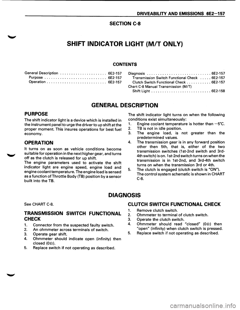
The control system schematic is shown in CHART
C-8.
DIAGNOSIS
See CHART C-8.
TRANSMISSION SWITCH FUNCTIONAL
CHECK
1. Connector from the suspected faulty switch.
2. An ohmmeter across terminals of switch.
3. Operate gear shift.
4. Ohmmeter should indicate open (infinity) then
closed (00).
5. Replace switch if not operating as described.
CLUTCH SWITCH FUNCTIONAL CHECK
1. Remove clutch switch.
2. Ohmmeter to terminal of clutch switch.
3. Operate the clutch switch.
4. Ohmmeter should read "closed" (00) then
"open" (infinity) when clutch switch is pressed.
5. Replace switch if not operating as described.
Page 854 of 1928
6E2-158 DRIVEABILITV AND EMISSIONS
CHART C-8
MANUAL TRANSMISSION (M/T) SHIFT LIGHT CHECK
Circuit Description:
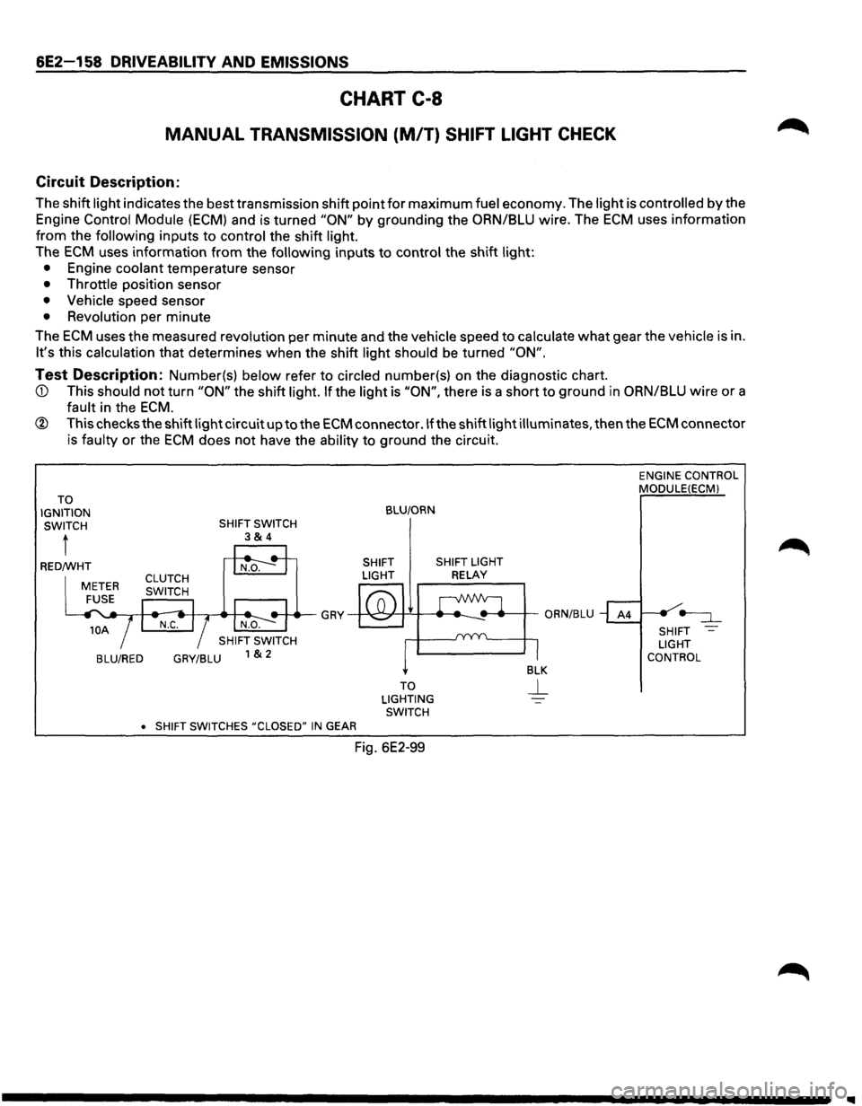
The shift light indicates the best transmission shift point for maximum fuel economy. The light is controlled by the
Engine Control Module
(ECM) and is turned "ON" by grounding the ORN/BLU wire. The ECM uses information
from the following inputs to control the shift light.
The
ECM uses information from the following inputs to control the shift light:
• Engine coolant temperature sensor
• Throttle position sensor
• Vehicle speed sensor
• Revolution per minute
The
ECM uses the measured revolution per minute and the vehicle speed to calculate what gear the vehicle is in.
It's this calculation that determines when the shift light should be turned "ON".
Test Description: Number(s) below refer to circled number(s) on the diagnostic chart.
ECM.
® This checks the shift light circuit up to the ECM connector .If the shift light illuminates, then the ECM connector
is faulty
or the ECM does not have the ability to ground the circuit.
TO
IGNITION SWITCH
t
BLU/RED GRY/BLU
•
SHIFT SWITCHES #CLOSED" IN GEAR
BLU/ORN
SHIFT SHIFT LIGHT
LIGHT
RELAY
TO
LIGHTING SWITCH
Fig. 6E2-99
ENGINE CONTROL
MODULE(ECMl
SHIFT
LIGHT
CONTROL
Page 855 of 1928
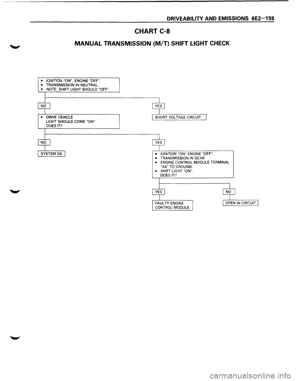
DRIVEABILITY AND EMISSIONS 6E2-159
CHART C-8
MANUAL TRANSMISSION (,MfT) SHIFT LIGHT CHECK
• IGNITION "ON", ENGINE "OFF".
• TRANSMISSION IN NEUTRAL. • NOTE: SHIFT LIGHT SHOULD "OFF".
•
DRIVE VEHICLE
LIGHT SHOULD COME "ON" DOES IT?
• IGNITION
"ON" ENGINE "OFF".
• TRANSMISSION IN GEAR • ENGINE CONTROL MODULE TERMINAL "A4" TO GROUND.
• SHIFT LIGHT "ON".
DOES
IT?
Page 857 of 1928
DRIVEABILITV AND EMISSIONS 6E2-161
SECTION C-1 0
AIR CONDITIONING (A/C) COMPRESSOR CLUTCH CONTROL
SYSTEM
CONTENTS
General Description ..................... 6E2-161 On-Vehicle Service ...................... 6E2-161
Operation ........................... 6E2-161 Chart C-10 Air Conditioning (A/C) System
Diagnosis ............................. 6E2-161 Functional Check ...................... 6E2-162
GENERAL DESCRIPTION
OPERATION
This system consists of a high pressure cut-out switch,
Air Conditioning (A/C) compressor
relay, A/C thermo
switch relay, A/C controller and the compressor.
The high pressure cut-out switch
(normally closed),
opens when the head pressure gets too high. This will
disable
the A/C clutch, before damage can occur to the
compressor or other
A/C components.
When
A/C control switch is "ON" and the high pressure
switch and thermo switch are
closed, a request signal
is sent to the Engine Control Module (ECM). The ECM
will then energize the A/C clutch through the A/C
clutch relay. The A/C controller which is separate from
the ECM will then turn the A/C cooling fan "ON".
The A/C controller controls the A/C cooling fan, as well
as sending a signal to the ECM on model equipped with
automatic transmission.
The
ECM will disable the A/C clutch during Wide Open
Throttle,
or high power steering loads. The ECM has a
slight delay for clutch engagement to allow for the idle
to slightly increase. Refer to CHART C-1 0 for wiring and
circuit description.
DIAGNOSIS
Chart C-10 should be used for the electrical portion of
the A/C circuit. Section 1 B should be used for
diagnosing the refrigerant portion of the system. The
"Scan tool" will be used in diagnosing the system, as it
has the ability to read the A/C request inputto the ECM,
as well as displaying when the ECM has commanded
the
A/C clutch "ON".
ON-VEHICLE SERVICE
For removal and replacement of A/C components,
refer to
A/C (SECTION 1 B) in this Manual.
Page 859 of 1928
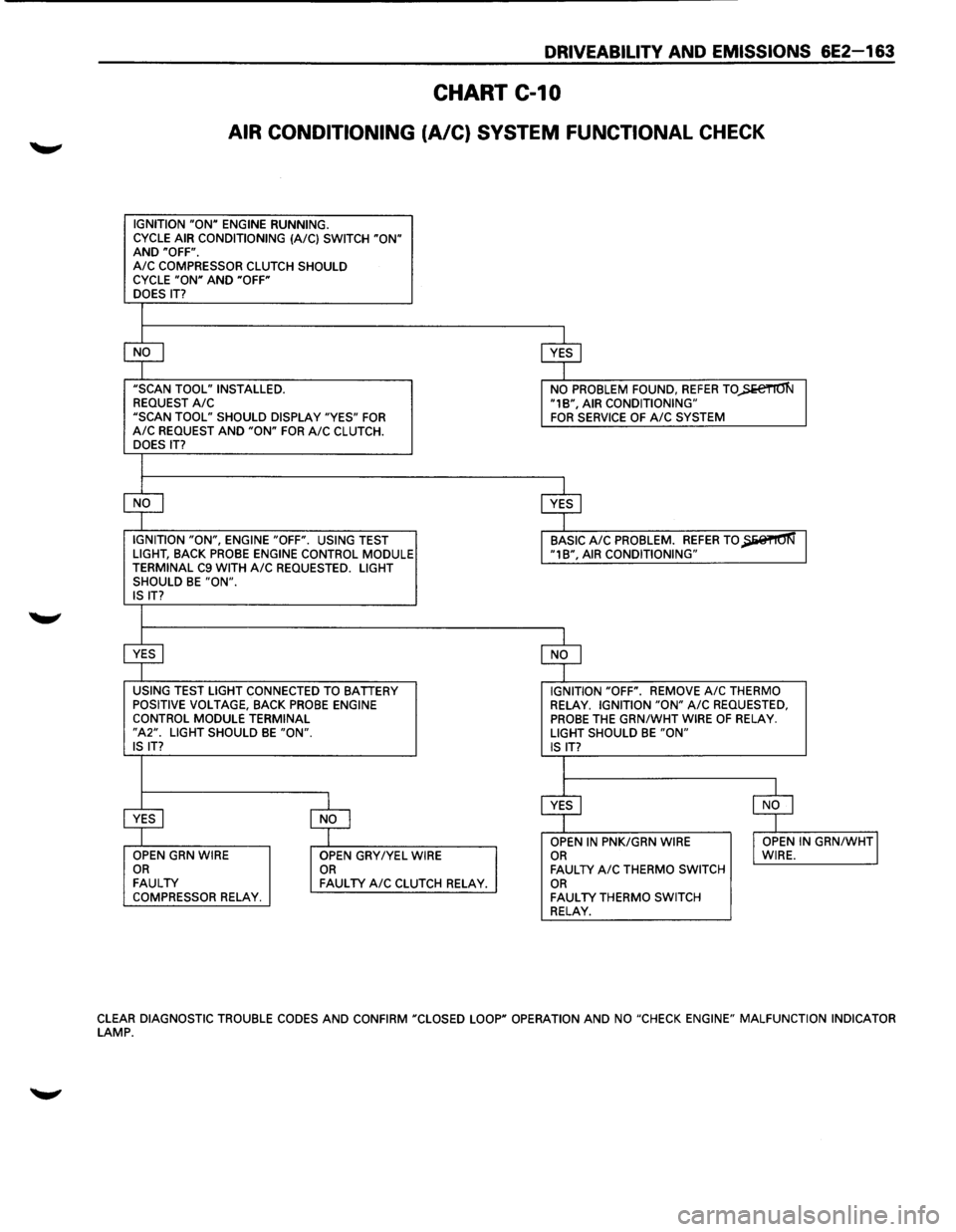
DRIVEABILITV AND EMISSIONS 6E2-163
CHART C-10
AIR CONDITIONING (A/C) SYSTEM FUNCTIONAL CHECK
IGNITION "ON" ENGINE RUNNING.
CYCLE AIR CONDITIONING (A/C) SWITCH "ON" AND "OFF". A/C COMPRESSOR CLUTCH SHOULD
CYCLE "ON" AND "OFF"
DOES IT?
$
$
"SCAN TOOL" INSTALLED.
NO PROBLEM FOUND, REFER TO)>e€TIO'N REQUEST A/C "1B", AIR CONDITIONING"
"SCAN TOOL" SHOULD DISPLAY "YES" FOR FOR SERVICE OF A/C SYSTEM A/C REQUEST AND "ON" FOR A/C CLUTCH.
DOES IT?
$
$
IGNITION "ON", ENGINE "OFF". USING TEST BASIC A/C PROBLEM. REFER TO~ LIGHT, BACK PROBE ENGINE CONTROL MODULE "1B", AIR CONDITIONING"
TERMINAL C9 WITH A/C REQUESTED. LIGHT
SHOULD BE "ON". IS IT?
$ $
USING TEST LIGHT CONNECTED TO BATTERY IGNITION "OFF". REMOVE A/C THERMO
POSITIVE VOLTAGE, BACK PROBE ENGINE RELAY. IGNITION "ON" A/C REQUESTED, CONTROL MODULE TERMINAL PROBE THE GRN/WHT WIRE OF RELAY. "A2". LIGHT SHOULD BE "ON". LIGHT SHOULD BE "ON" IS IT?
IS IT?
I
$ $
~ $ OPEN IN PNK/GRN WIRE I OPEN IN GRN/WHTJ OPEN GRN WIRE
OPEN GRY/YEL WIRE OR WIRE. OR OR FAULTY A/C THERMO SWITCH FAULTY FAULTY A/C CLUTCH RELAY. OR COMPRESSOR RELAY. FAULTY THERMO SWITCH RELAY.
CLEAR DIAGNOSTIC TROUBLE CODES AND CONFIRM "CLOSED LOOP" OPERATION AND NO "CHECK ENGINE" MALFUNCTION INDICATOR LAMP.
Page 883 of 1928

AUTOMATIC TRANSMISSION (4L30-E) 7 A-11
FUNCTIONS OF INPUT /OUTPUT COMPONENTS
Components Function
Speed sensor
Senses rotation
of output shaft and feeds the data to Transmission
(fixed
to transmission (T/M)) Control Module (TCM)
Throttle Senses the extent of throttle valve opening and the speed of the throttle
position sensor (TPS) valve lever motion to open the valve and feeds the data to TCM (fed to
(fixed to engine)
Engine Control Module (ECM) also)
I
Brake Switch (SW) Senses whether the driver has pressed the brake pedal or not and feeds
N (fixed
to brake pedal) the
information to TCM
p Kick-down SW (fixed to Senses whether the driver has pushed the accelerator pedal fully or not
u accelerator pedal) and feeds the information to TCM
T Mode
SW (fixed to T/M) Senses the select lever position and feeds the information to TCM
s Power drive SW Senses whether the driver has selected the power mode and feeds the
I (fixed to front console) information to TCM
G T/M
oil temp. sensor
Senses the T/M oil temperature and feeds the data to TCM
N Engine
coolant Senses the engine cooling water temperature and feeds the data to TCM
A temperature
SW (feeds the signal from ECM)
L
Engine speed
signal Feeds the signals monitoring engine speed to TCM from Ignition Control
Module
(fed to ECM also)
Air conditioning Senses whether the air conditioner has been switched on or not and
information feeds the information
to TCM
On-board diagnostic
input By monitoring the Ground (GND), the location of failure is shown on the
T/M
monitor lamp ("CHECK TRANS") by flashing the diagnostic trouble
code
Winter switch
Senses whether the driver has selected the winter mode, and feeds the
(fixed
to front console) information to TCM
Cruise
controller Downshift takes place when Overdrive OFF signal is received from auto
(Overdrive
OFF signal) cruise control unit
Shift
solenoid Selects shift point and gear position suited to the vehicle running con-s 1-2/3-4, 2-3
dition on the basis of TCM output 0 Band apply solenoid
Controls oil flow suited to the vehicle running condition on the basis of L
E TCM output
0 N
Torque
Converter Controls clutch engagement/disengagement suited to the vehicle
u 0 Clutch solenoid running condition on the basis of TCM output
T I Force motor Adjusts the oil pump delivery pressure to line pressure suited to the p D
(Pressure regulator vehicle running condition on the basis of TCM output u valve) T
Power drive mode lamp
Informs the driver whether the vehicle is in power mode or not
s Winter drive mode lamp Informs the driver whether the vehicle is in winter mode or not
I T/M monitor lamp Informs the driver of failure in the system. It also displays the self diagnosis
G
("CHECK TRANS") code.
N Data Link Connector
(DLC) When connected with TECH 1 or tester, can communicate the data for A
L function
check, etc. (fed to ECM also). When TECH 1 is not connected, can
communicate the
signal for torque management with ECM.
Self-diagnosis connector
When short-circuited with the bipolar connector, the T/M monitor lamp
displays
a failure by code.
ATF warning
lamp Lights when ATF oil temperature rises.
ABS signal When the select lever is at "Reverse" or "L" range, sends a signal to the
ABS controller as one of the ABS control conditions.
Page 892 of 1928
7 A-20 AUTOMATIC TRANSMISSION (4L30-E)
CHECKING TRANSMISSION FLUID
LEVEL AND CONDITION
Checking fluid level and condition (color and odor)
at
regular intervals will provide early diagnosis
information about the transmission. This inform
ation may be used to correct a condition that, if not
detected early, could result in major transmission
repairs.
IMPORTANT: When new, automatic transmission
fluid is red in color. As the vehicle is driven, the
transmission
fluid will begin to look darker in color.
The
color may eventually appear light brown.
A DARK
brown color with burnt odor may indicate
excessive
fluid deterioration and signal a need for
fluid change.
FLUID LEVEL
When adding
or changing fluid, use only DEXRON
®-Ill.
Refer to the Maintenance and Lubrication (Section 0
of this manual) for maintenance information and
servicing
interval.
\f CAUTION: DO NOT OVERFILL
Overfilling will cause foaming, loss ~f fluid,
abnormal shifting and possible damage to
the transmission.
1. Start engine and drive vehicle until normal AfT
oil operating temperature is reached:
NOTE: The automatic transmission fluid level
must be checked with the vehicle at normal
A/T oil operating temperature: 75 TO 85°C
(167 TO 185°F) MEASURED WITH TECH1 SCAN
TOOL.
Temperature will greatly affect transmission
fluid level.
If the vehicle is not at normal AfT oil operating
temperature and the proper checking
procedures are
not followed, the result could
be a false reading of the fluid level indicator
and
an incorrect adjustment of the fluid level.
2. Park vehicle on level ground.
3. Move gear selector to "Park".
4. Apply parking brake and block wheels.
5. Allow vehicle to idle for 3 minutes with all
accessories turned off.
6. Check fluid level with engine running at idle:
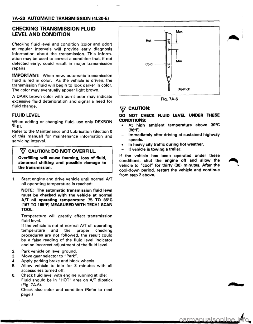
Fluid should
be in "HOT" area on AfT dipstick
(Fig. 7A-6).
Check also color and condition (Refer to next
page.)
Hot
Cold ---IIU 0
0
Min
Dipstick
Fig. 7A-6
\f CAUTION:
DO NOT CHECK FLUID LEVEL UNDER THESE
CONDITIONS: •
At high ambient temperature above 30°C
(86°F).
Immediately after driving at sustained highway
speeds.
• In heavy city traffic during hot weather.
If vehicle is towing a trailer.
If the vehicle has been operated under these
conditions,
shut the engine off and allow the
vehicle to "cool" for thirty (30) minutes. After the
cool-down period, restart the vehicle and continue
from step 2 above.
'~I
......
Page 1024 of 1928
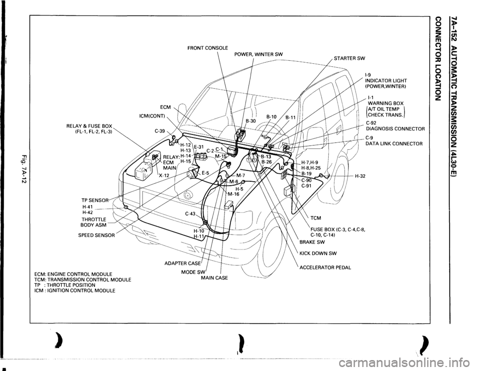
•
, cCi" -.J )> I .... N
RELAY
& FUSE BOX
(FL-1, FL-2, FL-3)
THROTTLE BODYASM SPEED SENSOR
ECM:
ENGINE CONTROL
MODULE
TCM:
TRANSMISSION CONTROL
MODULE
TP :THROTTLE
POSITION
ICM
: IGNITION CONTROL
MODULE
)
ECM
ICM(CONT) FRONT
CONSOLE
MODESW
MAIN
CASE
,}
~H-32
FUSE BOX
(C-3,
C-4,C-8,
C-10,
C-14)
BRAKE
SW
KICK DOWN
SW
ACCELERATOR PEDAL
1-9 INDICATOR LIGHT
(POWER, WINTER) 1-1 WARNING BOX (AfT
OIL
TEMP )
CHECK TRANS.
C-92 DIAGNOSIS CONNECTOR C-9 DATA
LINK CONNECTOR
}
(') 0 2
2 m a ::IJ r-0 (') !4 0 2
" t .... C1l N l> c: a s: !4 n -4 ::IJ l> 2 rA s: c;; rA 0 2 ~ ~ 0 I m