dimensions ISUZU TROOPER 1995 Workshop Manual
[x] Cancel search | Manufacturer: ISUZU, Model Year: 1995, Model line: TROOPER, Model: ISUZU TROOPER 1995Pages: 1928
Page 99 of 1928
FRAME 2A-1
FRAME, BUMPERS AND SHEET METAL
CONTENTS
Frame . . . . . . . . . . . . . . . . . . . . . . . . . . . . . . . . . . . . . . . . . . . . . . . . . . . . . . . . . . . . . . . . . . . . . . . . Section 2A
Bumpers . . . . . . . . . . . . . . . . . . . . . . . . . . . . . . . . . . . . . . . . . . . . . . . . . . . . . . . . . . . . . . . . . . . . . Section
28
Sheet Metal . . . . . . . . . . . . . . . . . . . . . . . . . . . . . . . . . . . . . . . . . . . . . . . . . . . . . . . . . . . . . . . . . . Section 2C
SECTION 2A
FRAME
NOTE:
Fasteners are important attaching parts in that they could affect the performance of vital components and
systems,
and/or could result in major repair expense. They must be replaced with one of the same part number or
with an equivalent part if replacement becomes necessary. Do not use a replacement part of lesser or substitute
design. Torque
values must be used as specified during reassembly to assure proper retention of these parts.
Refer to Torque
Value Chart in the general information of Section "OA".
CONTENTS
General Description ................................................................... 2A-1
Frame Dimensions .................................................................... 2A-2
GENERAL DESCRIPTION
Proper frame alignment is important to assure normal
vehicle life
and performance of many other parts of the
vehicle. If
the vehicle has
been involved in a fire, collision or has
been
overloaded, it is necessary to check the frame
alignment.
•
Page 100 of 1928
2A-2 FRAME
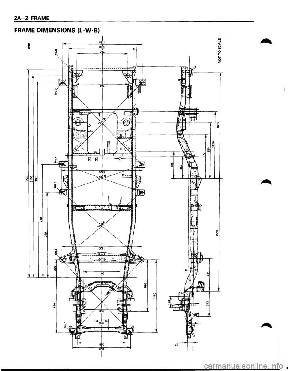
FRAME DIMENSIONS (L · W ·B)
E E
I 86~1
0 0~ 0 L
99L 068 £8
w ...J < &!
~ 1-0 z
.............................. _______________________________________ , .
Page 101 of 1928
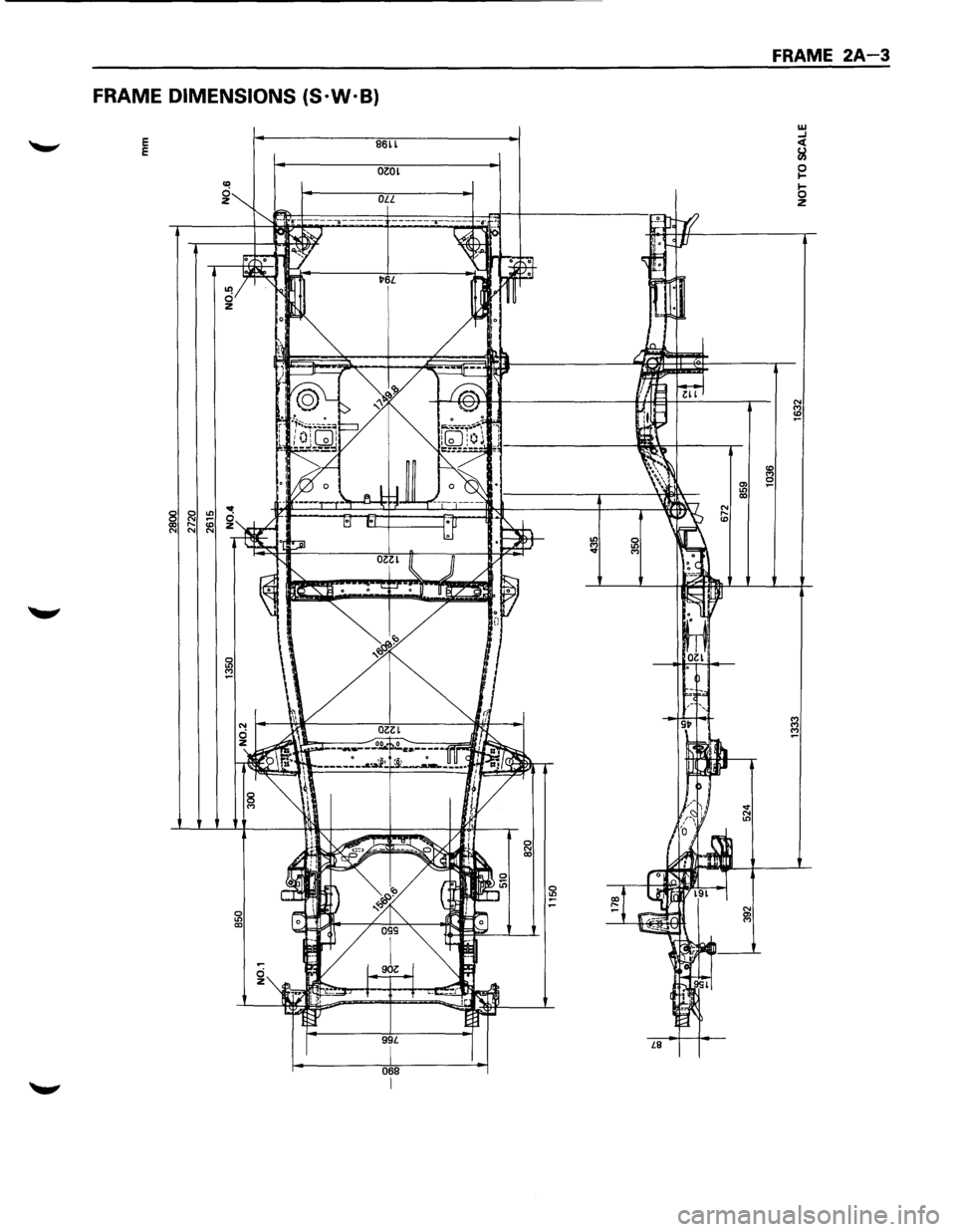
FRAME DIMENSIONS (S·W·B)
E E B6ll
OZOL
068
FRAME 2A-3
w ....1 <( &l
~
b z
Page 272 of 1928
48-30 REAR AXLE
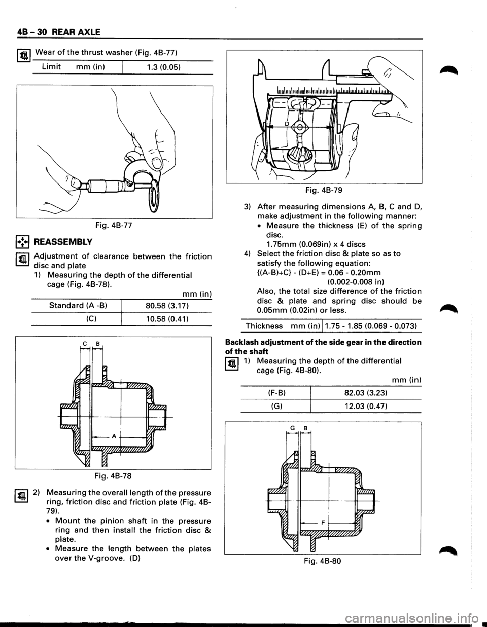
lfil!.l Wear of the thrust washer (Fig. 48-77)
Limit mm (in) I 1.3 (0.05)
Fig. 48-77
l•!•l REASSEMBLY
l"fll Adjustment of clearance between the friction
~ disc and plate
1) Measuring the depth of the differential
cage (Fig. 48-78).
~ 2)
mm(in)
Standard (A -8) 80.58 (3.17)
(C) 10.58 (0.41)
c 8
Fig. 48-78
Measuring the overall length ofthe pressure
ring,
friction disc and friction plate (Fig. 48-
79).
• Mount the pinion shaft in the pressure
ring and then install the friction disc &
plate.
•
Measure the length between the plates
over the V-groove. (D) Fig.
48-79
3) After measuring dimensions A, 8, C and D,
make adjustment in the following manner:
• Measure the thickness (E) of the spring
disc.
1.75mm (0.069in) x 4 discs
4) Select the friction disc & plate so as to
satisfy the following equation:
{(A-8)+C}-(D+E) = 0.06-0.20mm
(0.002-0.008 in)
Also, the total size difference of the friction
disc & plate and spring disc should be
0.05mm (0.02in) or less.
Thickness mm (in) 11.75-1.85 (0.069-0.073)
Backlash
adjustment of the side gear in the direction
of the shaft
lfil!.l1) Measuring the depth of the differential
cage (Fig. 48-80).
mm(in)
(F-8) 82.03 (3.23)
(G) 12.03 (0.47)
G 8
Fig. 48-80
Page 273 of 1928
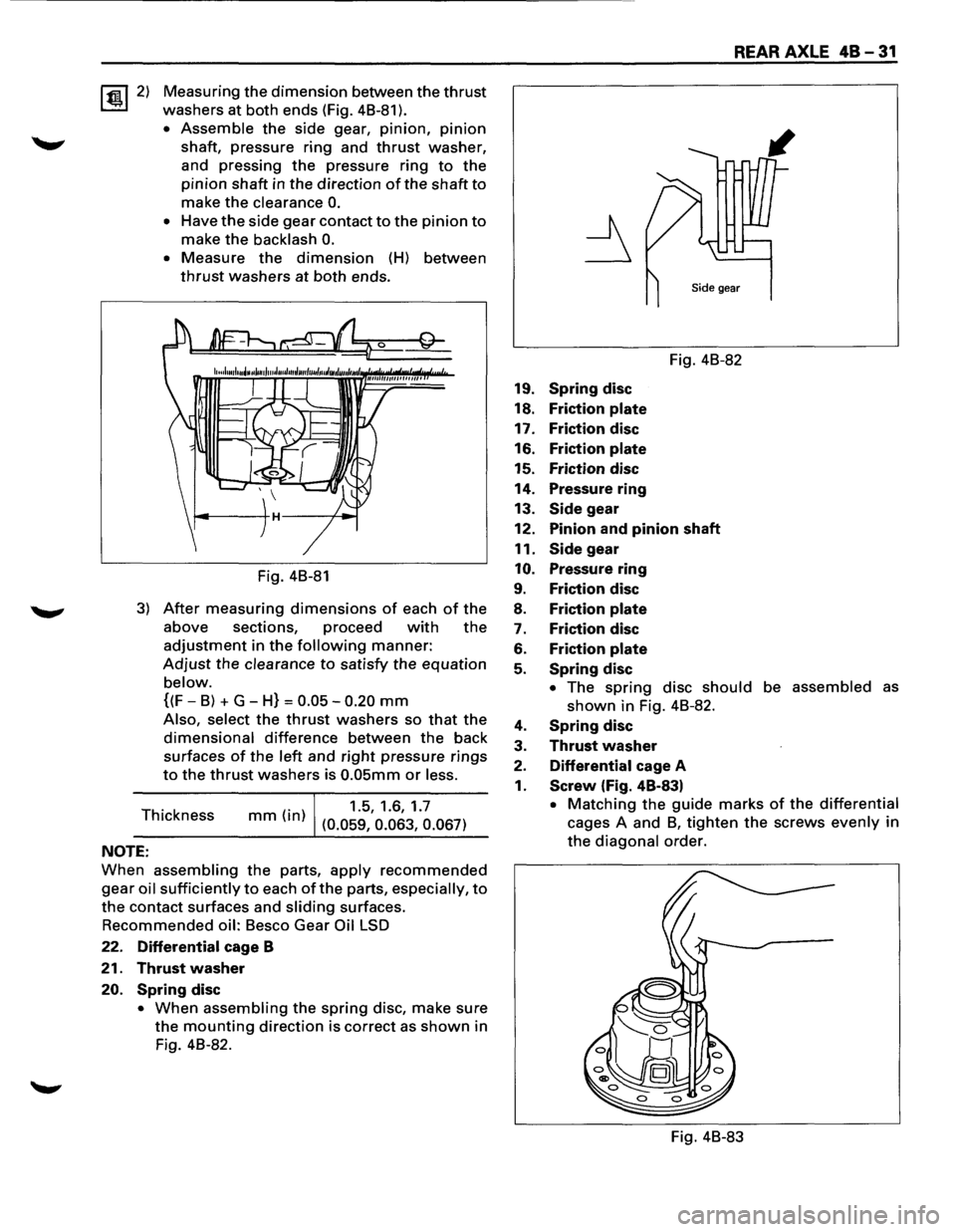
~2) Measuring the dimension between the thrust
washers at both ends (Fig. 48-81 ).
• Assemble the side gear, pinion, pinion
shaft, pressure ring and thrust washer,
and pressing
the pressure ring to the
pinion shaft in the direction of the shaft to
make the clearance 0.
• Have the side gear contact to the pinion to
make the backlash 0.
• Measure the dimension (H) between
thrust washers at both ends.
Fig. 48-81
3) After measuring dimensions of each of the
above sections, proceed with the
adjustment in the following manner:
Adjust the clearance to satisfy the equation
below.
{(F-8) + G-H} = 0.05-0.20 mm
Also, select the thrust washers so that the
dimensional difference between the back
surfaces
of the left and right pressure rings
to the thrust washers is 0.05mm or less.
Thickness (. )
1.5, 1.6, 1.7 mm In (0.059, 0.063, 0.067)
NOTE:
When assembling the parts, apply recommended
gear oil sufficiently to each of the parts, especially, to
the contact surfaces and sliding surfaces.
Recommended oil: 8esco Gear Oil LSD
22. Differential cage B
21. Thrust washer
20. Spring disc
• When assembling the spring disc, make sure
the mounting direction is correct as shown in
Fig. 48-82.
REAR AXLE 48-31
Fig. 48-82
19.
Spring disc
18. Friction plate
17. Friction disc
16. Friction plate
15. Friction disc
14. Pressure ring
13.
Side gear
12. Pinion and pinion shaft
11.
Side gear
10. Pressure ring
9. Friction disc
8. Friction plate
7. Friction disc
6. Friction plate
5. Spring disc
• The spring disc should be assembled as
shown in Fig. 48-82.
4. Spring disc
3. Thrust washer
2. Differential cage A
1. Screw (Fig. 48-83)
• Matching the guide marks of the differential
cages A and 8, tighten the screws evenly in
the diagonal order.
Fig. 48-83
Page 308 of 1928
4C -30 FRONT DRIVING AXLE
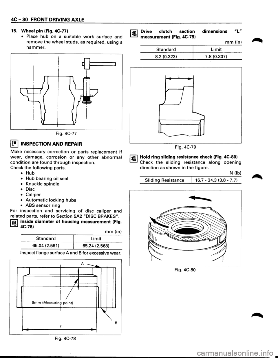
15. Wheel pin (Fig. 4C-77)
• Place
hub on a suitable work surface and
remove the
wheel studs, as required, using a
hammer.
Fig. 4C-77
I L•IINSPECTION AND REPAIR
Make necessary correction or parts replacement if
wear, damage, corrosion or any other abnormal
condition are found through inspection.
Check
the following parts.
• Hub
• Hub bearing oil seal
• Knuckle spindle
•
Disc
• Caliper
•
Automatic locking hubs
• ABS sensor ring
For inspection and servicing
of disc caliper and
related parts, refer to Section 5A2 "DISC BRAKES".
rfil Inside diameter of housing measurement (Fig.
~ 4C-78)
mm(in)
Standard Limit
65.04 (2.561)
65.24 (2.568)
Inspect flange surface A and 8 for excessive wear.
A ---....
1 I
'-/ I
i/ 8mm (Measuring point) I I
~.
e
Fig. 4C-78
rfil Drive clutch section
~ measurement (Fig. 4C-79)
Standard
8.2 (0.323)
L
Fig. 4C-79 dimensions
ulu
mm(in)
Limit
7.8
(0.307)
1@ 1 Hold ring sliding resistance check (Fig. 4C-80)
Check the sliding resistance along opening
direction as shown in the figure.
N (lb)
Sliding Resistance 16.7-34.3 (3.8-7.7)
......
Fig. 4C-80
Page 1790 of 1928
10-32 BODY
DOORS
FRONT DOOR ASSEMBLY
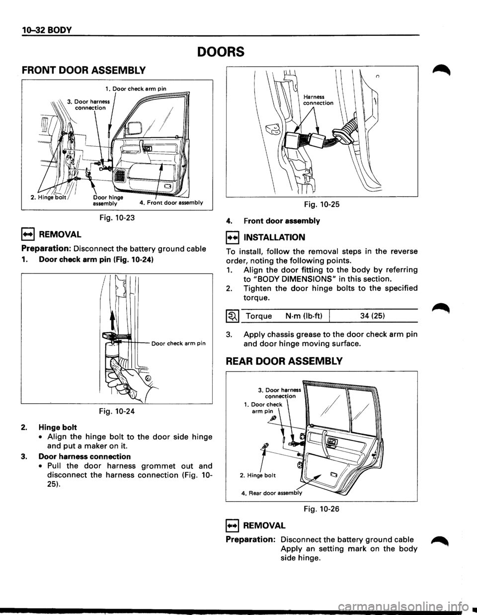
4. Front door assembly
Fig. 10-23
1++1 REMOVAL
Preparation: Disconnect the battery ground cable
1. Door check arm pin (Fig. 10-24)
Fig.
10-24
2. Hinge bolt
• Align the hinge bolt to the door side hinge
and
put a maker on it.
3. Door harness connection
• Pull the door harness grommet out and
disconnect the harness connection (Fig.
10-
25). Fig.
10-25
4. Front
door assembly
I++IINSTALLATION
To install, follow the removal steps in the reverse
order,
noting the following points.
1. Align the door fitting to the body by referring
to "BODY DIMENSIONS" in this section.
2. Tighten the door hinge bolts to the specified
torque.
~~~ Torque N·m (lb·ftl I 34 (25)
3. Apply chassis grease to the door check arm pin
and
door hinge moving surface.
REAR DOOR ASSEMBLY
Fig. 10-26
1++1 REMOVAL
Preparation: Disconnect the battery ground cable ~
Apply an setting mark on the body
side hinge.
•
Page 1791 of 1928
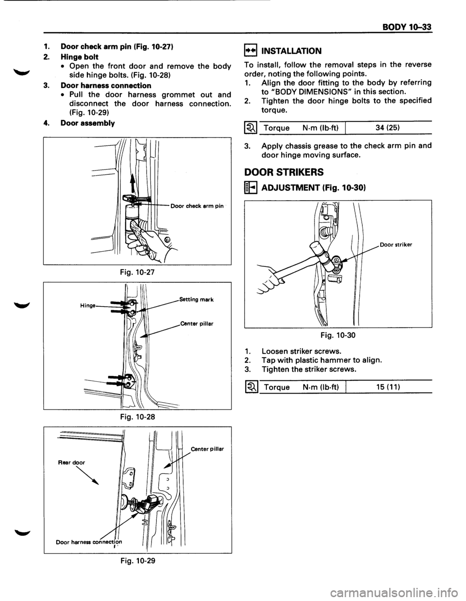
1. Door check arm pin (Fig. 10-27)
2. Hinge bolt
• Open the front door and remove the body
side hinge bolts. (Fig. 10-28)
3. Door harness connection
• Pull the door harness grommet out and
disconnect
the door harness connection.
(Fig. 1
0-29)
4. Door assembly
Door check arm pin
Fig. 10-27
Setting mark
Center pillar
Fig. 10-28
LJ
Center pillar
Rear door
~
Fig. 10-29
BODY 1o:-33
I++IINSTALLATION
To install, follow the removal steps in the reverse
order,
noting the following points.
1. Align the door fitting to the body by referring
to "BODY DIMENSIONS" in this section.
2. Tighten the door hinge bolts to the specified
torque.
1~1 Torque N·m (lb.ft) 34 (25)
3. Apply chassis grease to the check arm pin and
door hinge moving surface.
DOOR STRIKERS
I~EI ADJUSTMENT (fig. 10-30)
Door striker
Fig. 10-30
1. Loosen striker screws.
2. Tap with plastic hammer to align.
3. Tighten the striker screws.
~~~ Torque N·m {lb·ft) 15 (11)