fold seats ISUZU TROOPER 1995 Workshop Manual
[x] Cancel search | Manufacturer: ISUZU, Model Year: 1995, Model line: TROOPER, Model: ISUZU TROOPER 1995Pages: 1928
Page 518 of 1928
6A-2 GENERAL ENGINE MECHANICAL
NOTE:
•
During disassembly, be sure that the valve train
components are kept
together and identified so
that they can be re-installed in their original
locations.
• Before removing the cylinder head from the
engine and before disassembling the valve
mechanism, perform a compression test and note
the results.
1•! .. 1 DISASSEMBLY
(SOHC)
1. Camshaft timing pulley
2. Front plate
3. Camshaft bracket fixing bolts
4. Camshaft, oil seal and camshaft end plug
• Remove them with camshaft bracket.
5. Rockershaft assembly (Exhaust side)
6. Rockershaft assembly (Intake side)
7. Spark plug
\fl CAUTION:
VI • Do not remove the spark plugs when the head
and plugs are hot.
• Clean dirt and debris from spark plug recess
areas.
(DOHC)
1. Camshaft timing pulley
2. Front plate
3. Camshaft bracket fixing bolts
4. Chain tensioner fixing bolts
5. Camshaft, oil seal and camshaft end plug
• Remove them with chain and chain tensioner
6. Swing arm.
7. Hydraulic lash adjusters (HLA)
NOTE:
Immerse HLA in engine oil, taking care nottoturn it
upside down or sideways in order to prevent any
air
from entering into HLA.
8. Spark plug
\flCAUTION:
VI • Do not remove the spark plugs when the head
and plugs are hot.
• Clean dirt and debris from spark plug recess
areas.
f}l CLEAN
• Cylinder head
Carefully remove
all varnish, soot and carbon
to the bare metal. Do not use a motorized wire
brush on any gasket sealing surface.
IL'~'IINSPECTION AND REPAIR
• Cylinder head gasket and mating surfaces for
leaks, corrosion and blow-by. If the gasket has
failed, determine the cause. Insufficient
torque on head bolts
Improper installation
Loose
or warped cylinder head
Missing
dowel pins
- Warped case surface
1. Cylinder head bolts for damaged threads or
stretching and damaged heads caused by
improper use of tools.
\fl CAUTION:
VI Replace used cylinder head bolts.
2. Cylinder head for cracks, especially between valve
seats and in the exhaust ports.
3. Cylinder head deck for corrosion, sand particles in
head and porosity.
\fl CAUTION:
VI Do not attemptto weld the cylinder head. Replace
it.
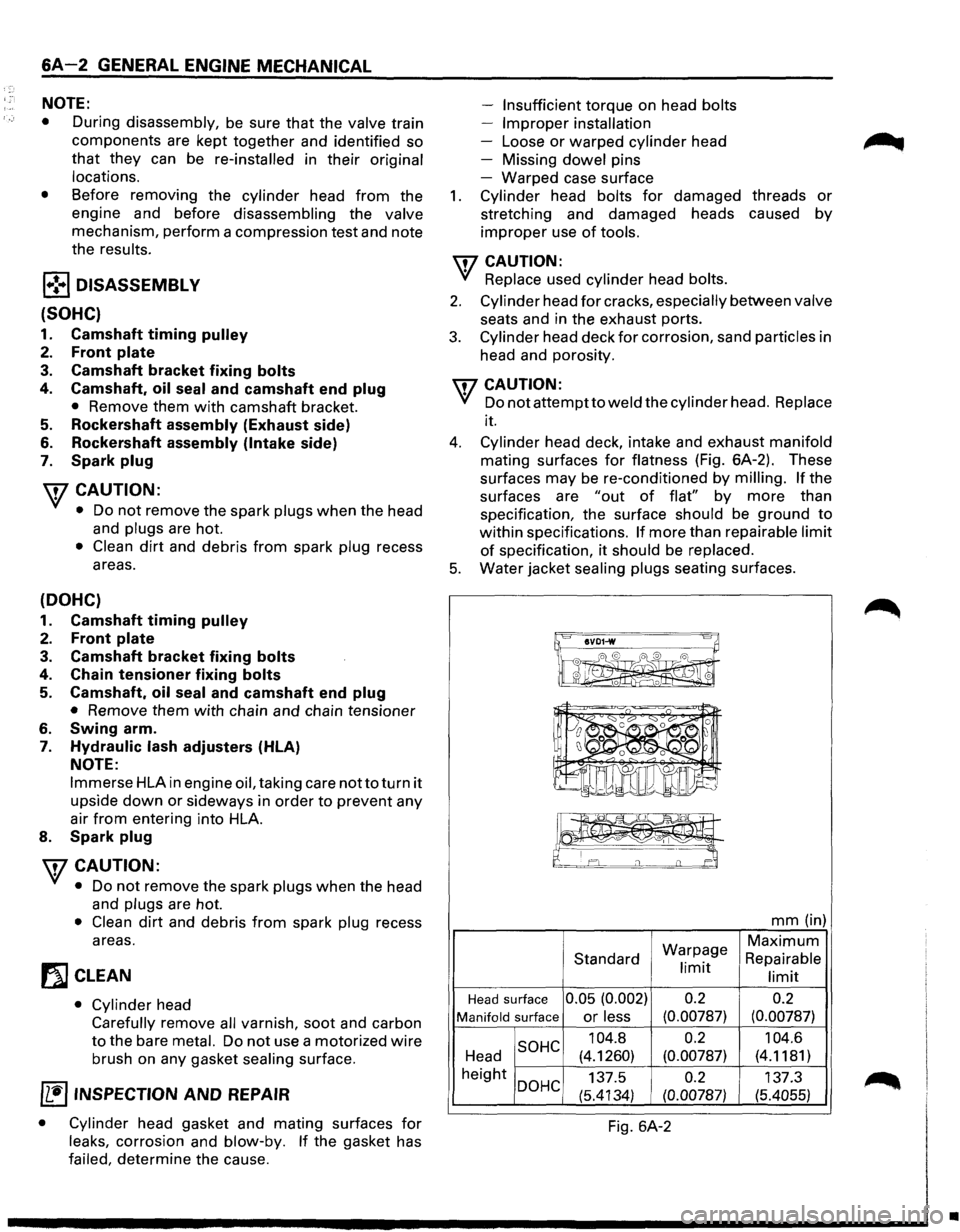
4. Cylinder head deck, intake and exhaust manifold
mating surfaces for flatness (Fig. 6A-2). These
surfaces
may be re-conditioned by milling. If the
surfaces are
"out of flat" by more than
specification, the surface should be ground
to
within specifications. If more than repairable limit
of specification, it should be replaced.
5. Water jacket sealing plugs seating surfaces.
IIVD1-w 8~
~ I 0 I ' 0 0 I 0
mm (in)
Warpage
Maximum
Standard Repairable limit limit
Head surface 0.05 (0.002) 0.2
0.2
Manifold surface or less (0.00787) (0.00787)
SOHC 104.8 0.2
104.6
Head (4.1260) (0.00787) (4.1181)
height
DOHC 137.5 0.2 137.3
(5.4134)
(0.00787) (5.4055)
Fig. 6A-2
•