fuse box ISUZU TROOPER 1995 Workshop Manual
[x] Cancel search | Manufacturer: ISUZU, Model Year: 1995, Model line: TROOPER, Model: ISUZU TROOPER 1995Pages: 1928
Page 325 of 1928
HYDRAULIC BRAKES 5A-5
ON-VEHICLE SERVICE
FILLING MASTER CYLINDER
RESERVOIR
'\fl CAUTION:
'VI • Use only specified brake fluid. Do not use any
fluid which contains a petroleum base. Do not
use a container which has been used for
petroleum based fluids or a container which is
wet with water. Petroleum based fluids will
cause swelling and distortion of rubber parts in
the
hydraulic brake system. Water mixed with
brake fluid lowers the fluid boiling point. Keep
all fluid containers capped to prevent contami
nation.
• Always fill the master cylinder reservoir when
the engine is
cold.
•
Never allow the brake fluid to come in contact
with the painted surfaces.
The master
cylinder reservoir must be kept properly
filled
to ensure adequate reserve and to prevent air
and moisture
from entering the hydraulic system.
However, because
of expansion due to heat absorbed
from the brakes and the engine, the reservoir must not
be overfilled. The brake fluid reservoir is on the master
cylinder, which is located under the hood on the
left
side of the cowl. Thoroughly clean reservoir cap
before
removal to avoid getting dirt into reservoir.
Remove cap and diaphragm.
Add fluid as required to
bring level to the "MAX" mark on the reservoir tank.
Use
"DOT 3" Hydraulic Brake Fluid. If the fluid cap
diaphragm is stretched, return
it to the original position
before
installing.
DETERIORATION OF BRAKE FLUID
Using any other brake fluid than specified or brake fluid
with mineral oil or water mixed in will drop the boiling
point of brake fluid. It may, in turn, result in vapor lock
or deteriorated rubber parts of the hydraulic system.
Be sure to change brake fluid at specified intervals.
If rubber parts are deteriorated, remove all the system
parts and
clean them with alcohol. Prior to reassembly,
dry the cleaned parts with air to remove the alcohol.
Replace all
hoses and rubber parts of the system.
LEAKAGE OF BRAKE FLUID
With engine idling, set shift lever in the neutral position
and continue to depress brake
pedal at a constant
pressure.
Should the pedal stroke become deeper gradually,
leak from the hydraulic pressure system is possible.
Make sure
by visual check that there is no leak.
BLEEDING BRAKE HYDRAULIC SYSTEM
A bleeding operation is necessary to remove air from
the hydraulic brake system whenever air is introduced
into the hydraulic system.
It may be necessary to bleed
the hydraulic system at all four brakes if air has been
introduced through a
low fluid level or by dis
connecting brake pipes at the master cylinder. If a
brake pipe is disconnected at one
wheel, only that
wheel cylinder/caliper needs to be bled. If pipes are
disconnected at any fitting
located between master
cylinder and brakes, then the brake system served by
the disconnected pipe must
be bled.
1. For 4-wheel Antilock Brake System (ABS)
equipped
vehicle, be sure to remove the ABS
main fuse
40A located at the relay and fuse box
before
bleeding air. If you attempt to bleed air
without removing the main fuse, air cannot be let
out thoroughly, and this may cause damage to the
hydraulic unit.
After bleeding air, be sure to
replace the ABS main fuse back to its original
position.
2. Set the parking brake completely, then start the
engine.
NOTE:
The vacuum booster will be damaged if the
bleeding operation is performed with the engine
off.
3. Remove the master cylinder reservoir cap.
4. Fill the master cylinder reservoir with brake fluid.
Keep the reservoir at least half full during the air
bleeding operation.
5. Always use new brake fluid for replenishment.
6. In replenishing brake fluid, take care that air
bubbles do not enter the brake fluid.
•
When the master cylinder is replaced or
overhauled, first bleed the air from the master
cylinder, then from each
wheel cylinder and
caliper following the procedures described
below.
Bleeding the master cylinder (Fig. 5A-1}
7. Disconnect the rear wheel brake pipe
cylinder (Fig. 5A-1 ). Check the fluid level
and replenish as necessary. If replenished, leave
the system for at least one minute.
8. Depress the brake pedal slowly once and hold it
depressed.
9. Completely seal the delivery port of the master
cylinder where the pipe was disconnected with
your finger, then release the brake pedal slowly.
10. Release your finger from the delivery port when
the brake
pedal returns completely.
11. Repeat steps 7 through 9 until the brake fluid
comes out of the delivery port during step 7.
Page 380 of 1928
5A3~12 REAR WHEEL ANTILOCK BRAKE SYSTEM
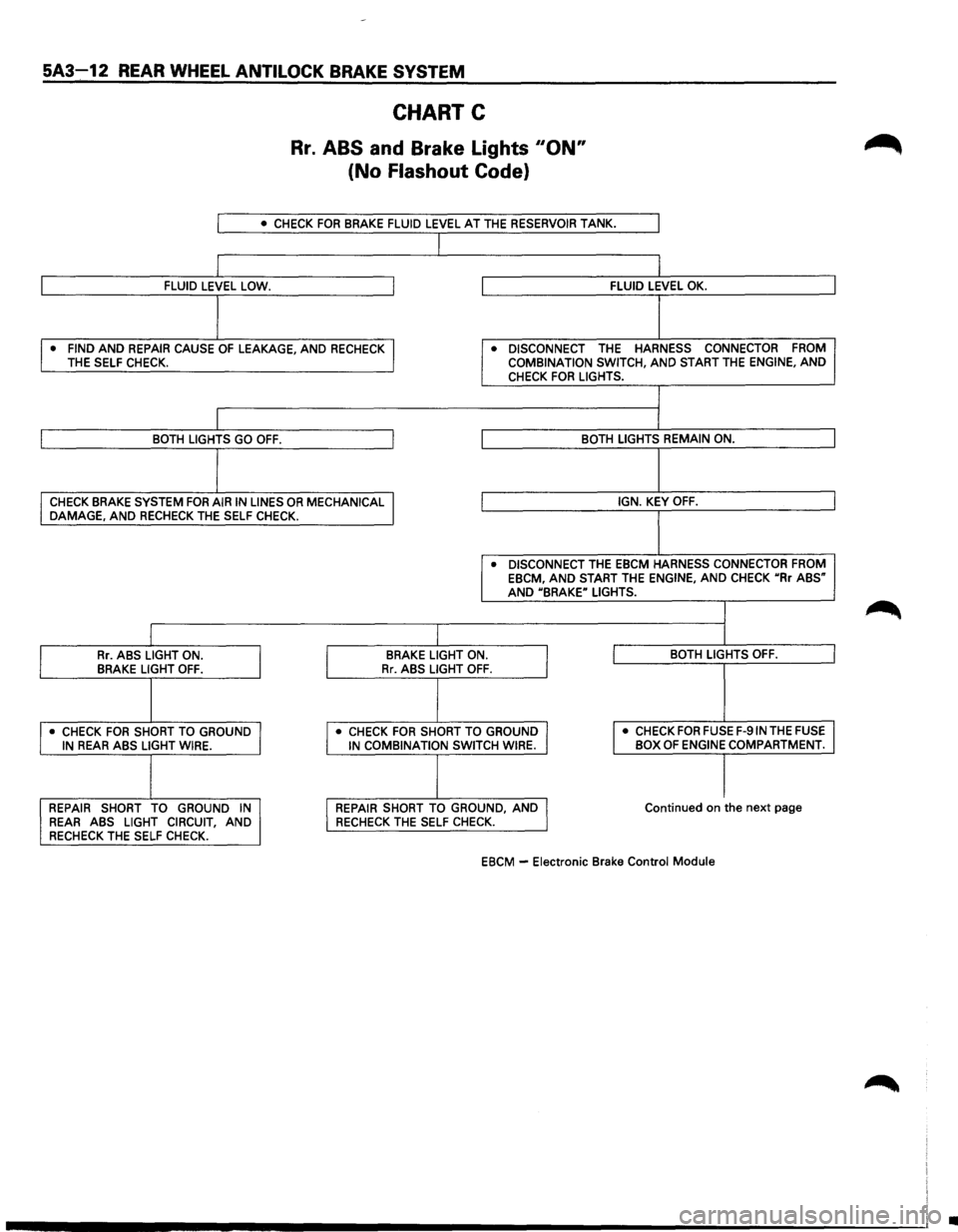
CHART C
Rr. ABS and Brake Lights 110N"
(No Flashout Code}
I • CHECK FOR BRAKE FLUID LEVEL AT THE RESERVOIR TANK.
I
I FLUID LEVEL LOW. I FLUID LEVEL OK.
I
• FIND AND REPAIR CAUSE OF LEAKAGE, AND RECHECK I • DISCONNECT THE HARNESS CONNECTOR FROM THE
SELF CHECK. COMBINATION SWITCH, AND START THE ENGINE, AND CHECK FOR LIGHTS.
I BOTH LIGHTS GO OFF. I BOTH LIGHTS REMAIN ON.
I
CHECK BRAKE SYSTEM FOR AIR IN LINES OR MECHANICAL I IGN. KEY OFF. DAMAGE, AND RECHECK THE SELF CHECK.
• DISCONNECT THE EBCM HARNESS CONNECTOR FROM EBCM, AND START THE ENGINE, AND CHECK uRr ABS" AND UBRAKE" LIGHTS.
I Rr. ABS LIGHT ON.
I
BRAKE LIGHT ON.
I I BOTH LIGHTS OFF. BRAKE LIGHT OFF. Rr. ABS LIGHT OFF.
I • CHECK FOR SHORT TO GROUND I • CHECK FOR SHORT TO GROUND I I
• CHECK FOR FUSE F-91N THE FUSE IN REAR ABS LIGHT WIRE. IN COMBINATION SWITCH WIRE. BOX OF ENGINE COMPARTMENT.
I I REPAIR
SHORT TO GROUND IN I REPAIR SHORT TO GROUND, AND J Continued on the next page REAR ABS LIGHT CIRCUIT, AND RECHECK THE SELF
CHECK.
RECHECK THE SELF CHECK.
EBCM -
Electronic Brake Control Module
•
Page 382 of 1928
5A3-14 REAR WHEEL ANTILOCK BRAKE SYSTEM
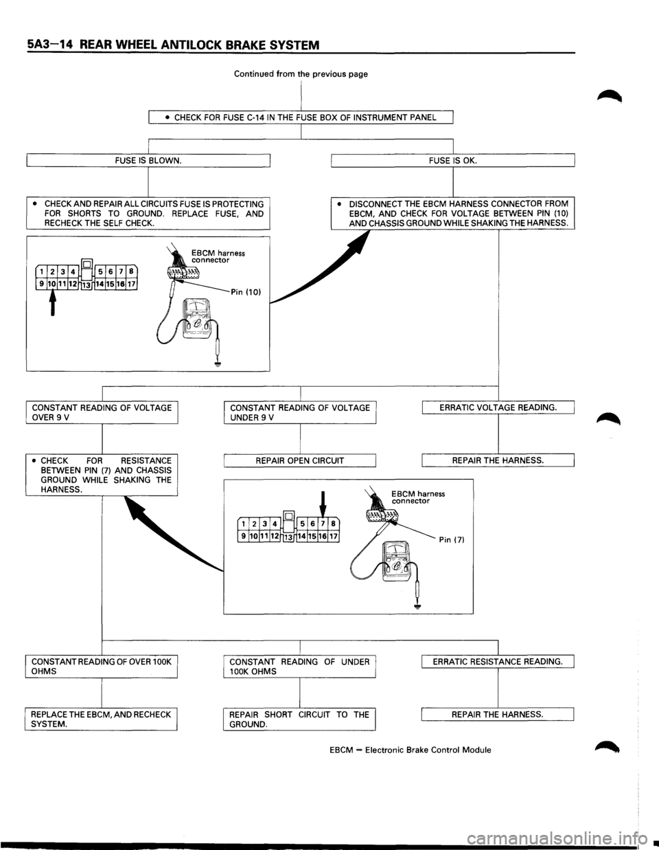
Continued from the previous page
• CHECK FOR FUSE C-14 IN THE FUSE BOX OF INSTRUMENT PANEL
FUSE IS BLOWN. FUSE IS OK.
•
CHECK AND REPAIR ALL CIRCUITS FUSE IS PROTECTING FOR SHORTS TO GROUND. REPLACE FUSE, AND RECHECK THE SELF CHECK.
• DISCONNECT THE EBCM HARNESS CONNECTOR FROM EBCM, AND CHECK FOR VOLT AGE BETWEEN PIN (1 0) AND CHASSIS GROUND WHILE SHAKING THE HARNESS.
CONSTANT READING
OF VOLTAGE OVER 9 V
• CHECK FOR RESISTANCE BETWEEN PIN (7) AND CHASSIS
GROUND WHILE SHAKING THE HARNESS.
CONSTANT READING
OF OVER 1 OOK OHMS
REPLACE THE EBCM, AND RECHECK SYSTEM. CONSTANT
READING
OF VOLTAGE UNDER 9 V
REPAIR OPEN CIRCUIT
CONSTANT
READING OF UNDER 100K OHMS
REPAIR SHORT CIRCUIT TO
THE GROUND. ERRATIC
VOLTAGE
READING.
REPAIR THE HARNESS.
ERRATIC RESISTANCE READING.
REPAIR
THE HARNESS.
EBCM = Electronic Brake Control Module
•
Page 415 of 1928
4-WHEEL ANTILOCK BRAKE SYSTEM (ABS) 5A4-5
DIAGNOSIS
GENERAL INFORMATION
ABS troubles can be classified to two types, those
which can be detected by the ABS warning light
and those which can be detected as a vehicle
abnormality by the driver.
In either case, locate the fault in accordance with
the "BASIC DIAGNOSTIC FLOWCHART" and repair.
Please refer to Section 5A, 5A1, 5A2, 5C for the
diagnosis
of mechanical troubles such as brake
noise, brake
judder (brake pedal or vehicle vibration
felt when braking), uneven braking, and parking
brake
trouble.
ABS SYSTEM SERVICE PRECAUTIONS
Required Tools and Items
Box Wrench
• Brake Fluid
Special Tool
Some diagnosis procedures in this section require
the installation of a special tool.
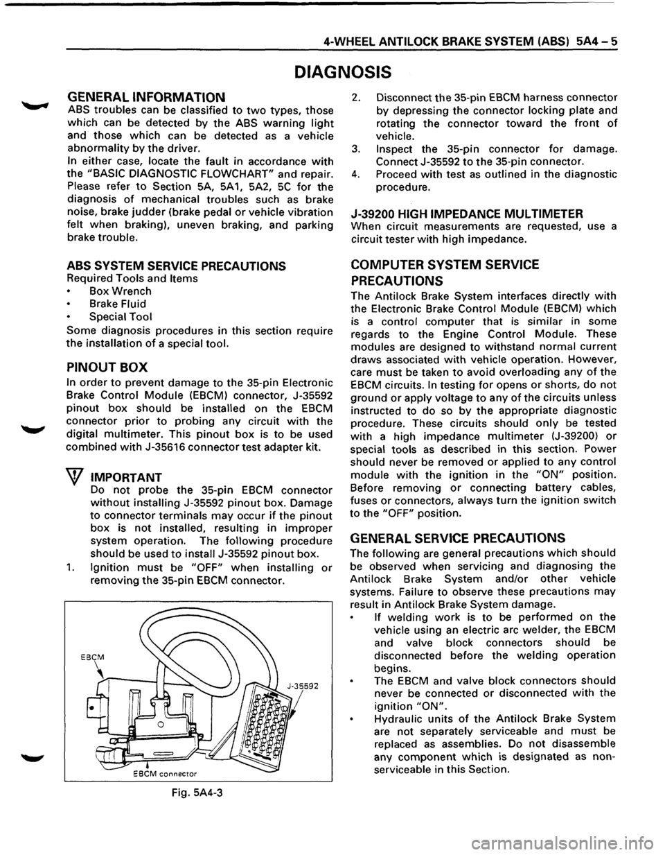
PINOUT BOX
In order to prevent damage to the 35-pin Electronic
Brake
Control Module (EBCM) connector, J-35592
pinout box should be installed on the EBCM
connector prior to probing any circuit with the
digital
multimeter. This pinout box is to be used
combined with J-35616 connector test adapter kit.
W IMPORTANT
Do not probe the 35-pin EBCM connector
without installing J-35592 pinout box. Damage
to connector terminals may occur if the pinout
box is not installed, resulting in improper
system operation. The following procedure
should be used to install J-35592 pinout box.
1. Ignition must be "OFF" when installing or
removing the 35-pin EBCM connector.
Fig. 5A4-3
2. Disconnect the 35-pin EBCM harness connector
by depressing the connector locking plate and
rotating
the connector toward the front of
vehicle.
3. Inspect the 35-pin connector for damage.
Connect J-35592 to the 35-pin connector.
4. Proceed with test as outlined in the diagnostic
procedure.
J-39200 HIGH IMPEDANCE MUL TIMETER
When circuit measurements are requested, use a
circuit tester
with high impedance.
COMPUTER SYSTEM SERVICE
PRECAUTIONS
The Antilock Brake System interfaces directly with
the Electronic Brake Control Module (EBCM) which
is a
control computer that is similar in some
regards
to the Engine Control Module. These
modules are designed to withstand normal current
draws associated with vehicle operation. However,
care
must be taken to avoid overloading any of the
EBCM circuits. In testing for opens or shorts, do not
ground or apply voltage to any of the circuits unless
instructed to
do so by the appropriate diagnostic
procedure. These circuits should only be tested
with a high impedance multimeter (J-39200) or
special tools as described in this section. Power
should never be removed or applied to any control
module with the ignition in the "ON" position.
Before removing
or connecting battery cables,
fuses
or connectors, always turn the ignition switch
to the "OFF" position.
GENERAL SERVICE PRECAUTIONS
The following are general precautions which should
be observed when servicing and diagnosing the
Antilock Brake System and/or
other vehicle
systems. Failure
to observe these precautions may
result in Antilock Brake System damage.
If welding work is to be performed on the
vehicle using an electric arc welder, the EBCM
and valve block connectors should be
disconnected before the
welding operation
begins.
The
EBCM and valve block connectors should
never be connected or disconnected with the
ignition "ON".
Hydraulic units of the Antilock Brake System
are not separately serviceable and must be
replaced
as assemblies. Do not disassemble
any
component which is designated as non
serviceable in
this Section.
Page 447 of 1928
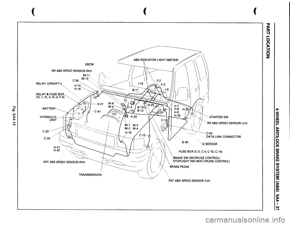
!! co U1 )> "" I .... w
(
EBCM
RR
ABS SPEED SENSOR
(RHl
.
RELAY:
UPSHIFT-2
""·,'-....."
M-11_
. ·r·---
..
C-39
M-12"-~.·
··..
> .. , ,·
~'
...
,
~~~~~
~.-·
& FUSE
BOX
· ••.
(FL-1,
FL-2, FL-6,
F-9~
'•
BATTERY HYDRAULIC
--+1--.-.
UNIT
C-33
--~----
C-34.
H-41
H-42
TRANSMISSION
(
~·~ rl r
( STARTER
SW
RR
ABS SPEED SENSOR
(LH)
\~· \'
-.
.
B-46
' G SENSOR
\
FUSE
BOX (C-3, C-4, C-10, C-14)
BRAKE
SW
(W/CRUISE CONTROL)
STOPLIGHT SW
(W/0
CRUISE CONTROL)
BRAKE PEDAL FRT
ABS
SPEED SENSOR
(LH)
(
"V )> ~ r-0 s 5 2
.... :e ::I: m
m r-l> 2 ~ r-0 0 ~ CCI ~ ~ m ~ Cl) -t m s: ~ ~ c.n t I w .....
Page 460 of 1928
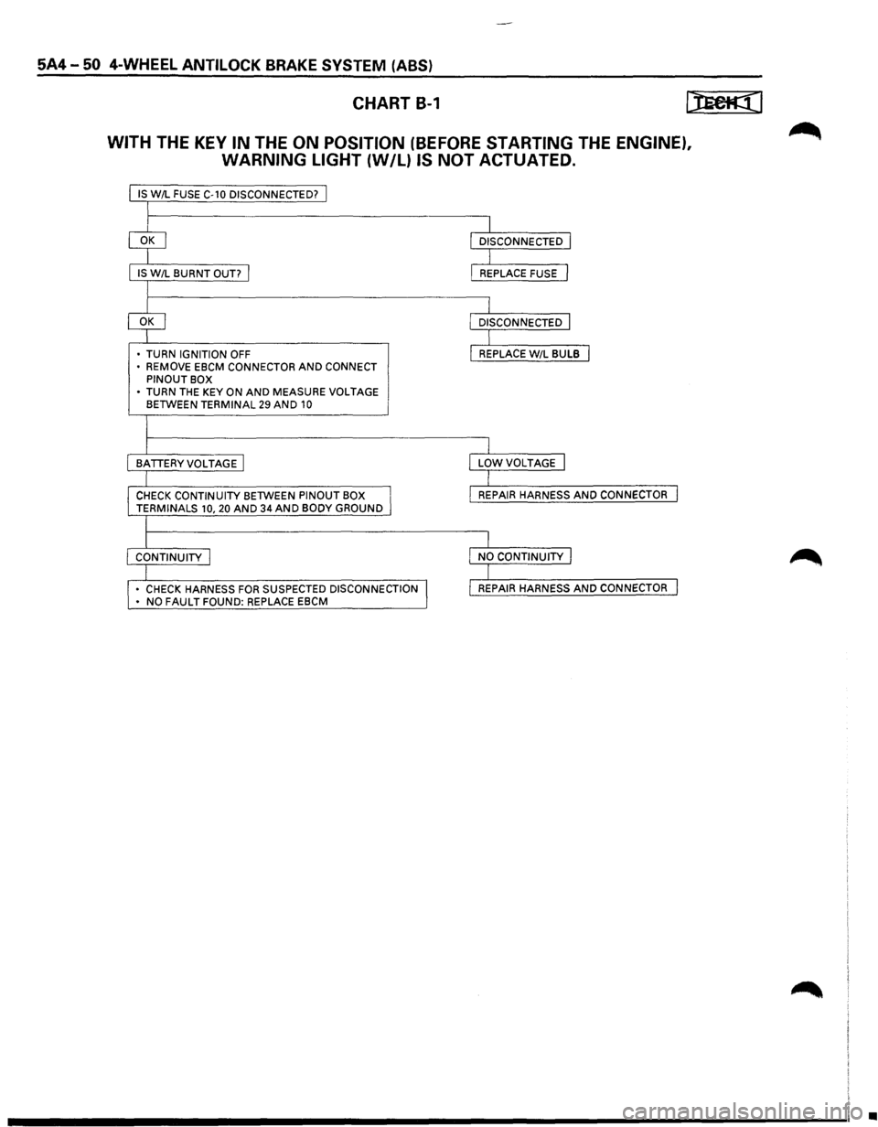
5A4-50 4-WHEEL ANTILOCK BRAKE SYSTEM (ABS)
CHART B-1
WITH THE KEY IN THE ON POSITION (BEFORE STARTING THE ENGINE),
WARNING LIGHT
{W/L) IS NOT ACTUATED.
IS W/L FUSE C-10 DISCONNECTED? j
I
IS W/L BURNT OUT? I
I
• TURN IGNITION OFF
• REMOVE EBCM CONNECTOR AND CONNECT PINOUT BOX
• TURN THE KEY ON AND MEASURE VOLTAGE BETWEEN TERMINAL 29 AND 10
I
I
BATTERYVOLTAGE I
I
CHECK CONTINUITY BETWEEN PINOUT BOX I TERMINALS 10, 20 AND 34 AND BODY GROUND
l
I CONTINUITY I
I • CHECK HARNESS FOR SUSPECTED DISCONNECTION I • NO FAULT FOUND: REPLACE EBCM
I
I
DISCONNECTED I
I L REPLACE FUSE J
I L DISCONNECTED J
I I REPLACE W/L BULB I
I
I
LOWVOLTAGE I
I
I
REPAIR HARNESS AND CONNECTOR I
I
I
NO CONTINUITY I
I I REPAIR HARNESS AND CONNECTOR I
•
Page 468 of 1928
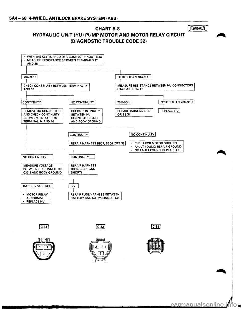
5A4-58 4-WHEEL ANTILOCK BRAKE SYSTEM (ABS)
CHART B-8 I):Eeti((l
HYDRAULIC UNIT (HU) PUMP MOTOR AND MOTOR RELAY CIRCUIT ~
(DIAGNOSTIC TROUBLE CODE 32)
• WITH THE KEY TURNED OFF, CONNECT PINOUT BOX
• MEASURE RESISTANCE BETWEEN TERMINALS 17 AND28
I 70n-9on I I OTHER THAN 70n-9on I
I
CHECK CONTINUITY BETWEEN TERMINAL 141 AND10 I MEASURE RESISTANCE BETWEEN HU CONNECTORS I C34-6 AND C34-11
I
I I I
CONTINUITY j NO CONTINUITY j 1 70(l-9ooJ I OTHER THAN 70n-9on I
I I I REMOVE HU CONNECTOR CHECK CONTINUITY I REPAIR HARNESS BB07 I I REPLACE HU I AND CHECK CONTINUITY BETWEEN HU OR BB08 BETWEEN PINOUT BOX
CONNECTOR C33-3 TERMINAL 14 AND 10 AND BODY GROUND
I
I
I CONTINUITY I NO CONTINUITY j
I I REPAIR HARNESS BB27, BB06 (OPEN) I • CHECK FOR MOTOR GROUND • FAULT FOUND: REPAIR GROUND
I • NO FAULT FOUND: REPLACE HU
NO CONTINUITY I CONTINUITY J
I MEASURE VOLTAGE REPAIR HARNESS
BETWEEN HU CONNECTOR BB06, BB27
(GND
C33-2 AND BODY GROUND SHORT)
BATTERYVOLTAGE I $
. MOTOR RELAY REPAIR FUSE/HARNESS BETWEEN I ABNORMAL BATTERY AND C33-2/CONNECTOR • REPLACE HU
•
Page 470 of 1928
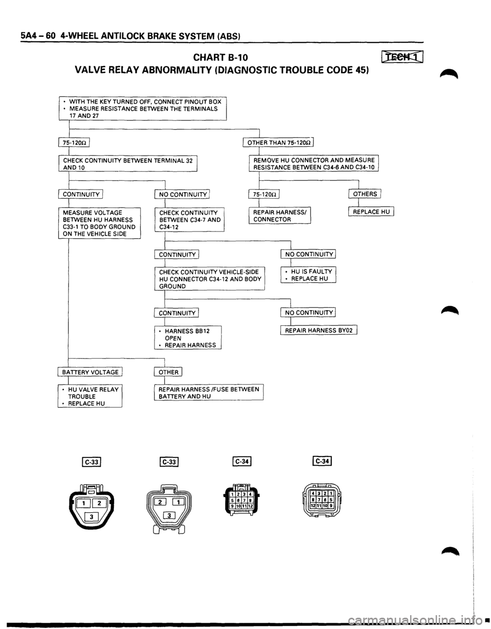
5A4-60 4-WHEEL ANTILOCK BRAKE SYSTEM (ABS)
CHART B-1 0 [):Ee@]
VALVE RELAY ABNORMALITY (DIAGNOSTIC TROUBLE CODE 45) ~
• WITH THE KEY TURNED OFF, CONNECT PINOUT BOX
• MEASURE RESISTANCE BETWEEN THE TERMINALS 17 AND 27
I 1s-12oo 1 I OTHER THAN 75-1200 J
I
CHECK CONTINUITY
BETWEEN TERMINAL 32 J AND10 I_ REMOVE HU CONNECTOR AND MEASURE I RESISTANCE BETWEEN C34-6 AND C34-10
I
I
I I
CONTINUITY I
NO CONTINUITY/ I75-120n/ I OTHERS I
I I
I
MEASURE
VOLTAGE CHECK CONTINUITY I REPAIR HARNESS/ J I REPLACE HU I
BETWEEN HU HARNESS BETWEEN C34-7 AND CONNECTOR
C33-1 TO BODY GROUND C34-12 ON THE VEHICLE SIDE I
I I CONTINUITY I l NO CONTINUITY I
I I
CHECK CONTINUITY VEHICLE-SIDE
,. HU IS FAULTY J HU CONNECTOR C34-12 AND BODY • REPLACE
HU GROUND
I
I I
CONTINUITY j I NO CONTINUITY I
I I • HARNESS BB12 l REPAIR HARNESS BY02 I OPEN
• REPAIR HARNESS
I BATTERY VOLTAGE j OTHER I
I
• HU VALVE RELAY I REPAIR HARNESS /FUSE BETWEEN I TROUBLE BATTERY AND HU • REPLACE HU
~1111 .. 1 2 3 4 5 617 8 9 101112 =
•
Page 502 of 1928
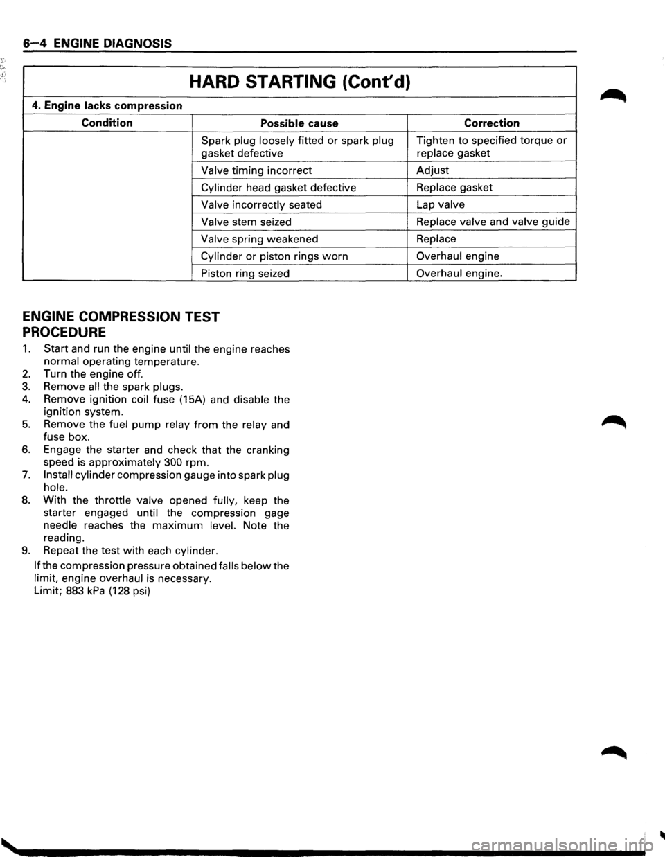
6-4 ENGINE DIAGNOSIS
HARD STARTING (Cont'd)
4. Engine lacks compression
Condition Possible cause
Spark plug loosely fitted or spark plug
gasket defective
Valve timing incorrect
Cylinder head gasket defective
Valve incorrectly seated
Valve stem seized
Valve spring weakened
Cylinder or piston rings worn
Piston ring seized
ENGINE COMPRESSION TEST
PROCEDURE
1. Start and run the engine until the engine reaches
normal operating temperature.
2. Turn the engine off.
3. Remove all the spark plugs.
4. Remove ignition coil fuse (15A) and disable the
ignition system.
5. Remove the fuel pump relay from the relay and
fuse box.
6. Engage the starter and check that the cranking
speed is approximately
300 rpm.
7. Install cylinder compression gauge into spark plug
hole.
8. With the throttle valve opened fully, keep the
starter engaged
until the compression gage
needle reaches the
maximum level. Note the
reading.
9. Repeat the test with each cylinder.
If
the compression pressure obtained falls below the
limit, engine overhaul is necessary.
Limit; 883
kPa (128 psi) Correction
Tighten
to specified torque or
replace gasket
Adjust
Replace gasket
Lap
valve
Replace valve
and valve guide
Replace
Overhaul engine
Overhaul engine.
Page 921 of 1928
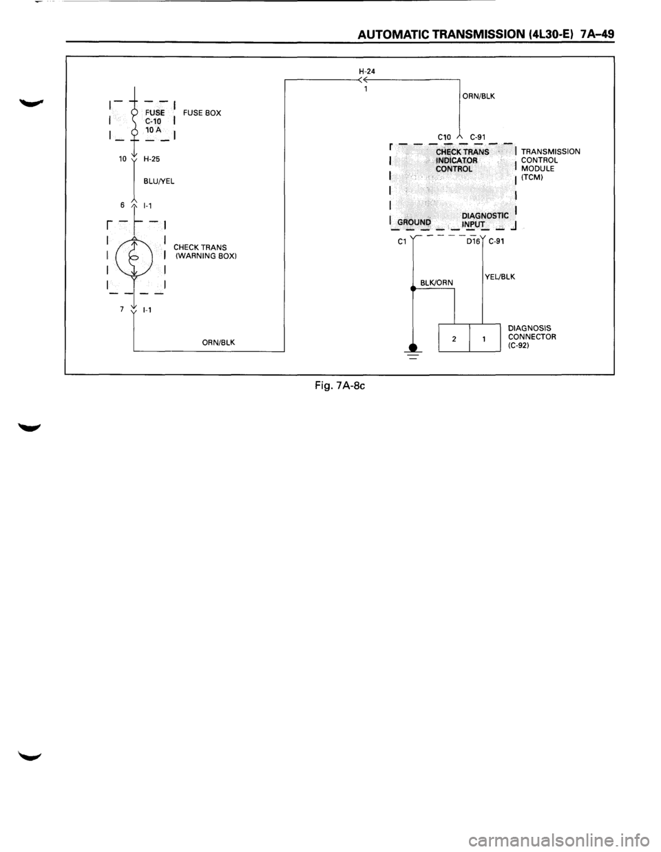
FUSE BOX
10 I H-25
BLU!YEL
6 t_l-1
r -~-~
I I CHECK TRANS I I (WARNING BOX)
I I
I
7 1-1
ORN/BLK
AUTOMATIC TRANSMISSION (4l30-E) 7 A-49
H-24
Fig. 7A-8c
ORN/BLK
C10 C-91
f - - -CHiCKTRANS--~ TRANSMISSION I tNOICAfiOR I CONTROL
I CONTROL MODULE I (TCM)
I I
I
I .. DIAGNOSTIC I _GROUNI',): _ _ t~U!_ ..:;;. .J
C1
BLK/ORN
D16 C-91
YEL!BLK
DIAGNOSIS
CONNECTOR
(C-92)