high beam ISUZU TROOPER 1995 Workshop Manual
[x] Cancel search | Manufacturer: ISUZU, Model Year: 1995, Model line: TROOPER, Model: ISUZU TROOPER 1995Pages: 1928
Page 1210 of 1928
8-20 CHASSIS ELECTRICAL
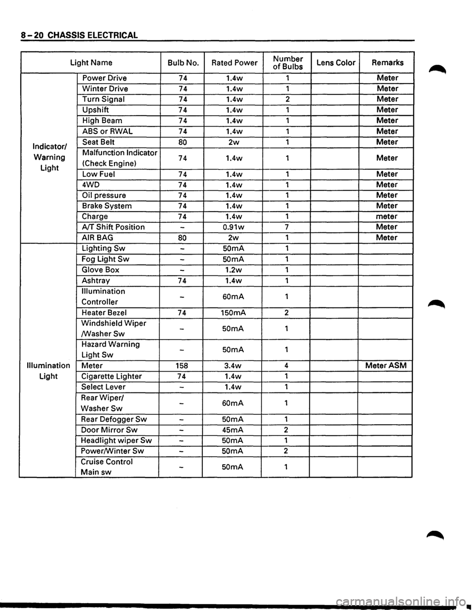
Light Name Bulb No. Rated Power Number Lens Color Remarks of Bulbs
Power Drive 74 1.4w 1
Meter
Winter Drive 74 1.4w
1 Meter
Turn Signal 74 1.4w 2 Meter
Upshift
74 1.4w 1 Meter
High Beam
74 1.4w 1 Meter
ABSorRWAL 74 1.4w 1 Meter
Indicator/ Seat Belt 80 2w 1 Meter
Warning Malfunction Indicator 74 1.4w
1 Meter
Light (Check
Engine)
Low Fuel 74 1.4w 1 Meter
4WD
74 1.4w 1 Meter
Oil pressure 74 1.4w 1 Meter
Brake System 74 1.4w 1 Meter
Charge 74 1.4w 1
meter
A/T Shift Position -0.91w 7 Meter
AIR BAG 80 2w 1 Meter
Lighting Sw -SOmA 1
Fog Light
Sw -SOmA 1
Glove Box -1.2w 1
Ashtray
74 1.4w 1
Illumination
60mA 1 -Controller
Heater Bezel 74 1SOmA 2
Windshield
Wiper SOmA 1 -/WasherSw
Hazard Warning SOmA 1 -Light Sw
Illumination Meter 158 3.4w 4 MeterASM
Light
Cigarette Lighter
74 1.4w
1
Select Lever -1.4w 1
Rear
Wiper/ 60mA 1 -WasherSw
Rear Defogger Sw -SOmA 1
Door
Mirror Sw -45mA 2
Headlight
wiper Sw -SOmA 1
Power/Winter
Sw -SOmA 2
Cruise Control
SOmA 1 -Main sw
II
Page 1213 of 1928
CHASSIS ELECTRICAL 8-23
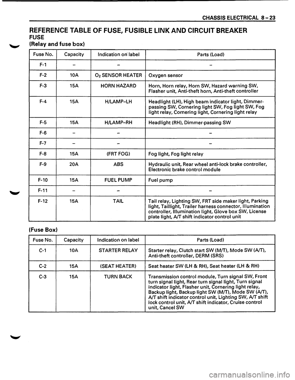
REFERENCE TABLE OF FUSE, FUSIBLE LINK AND CIRCUIT BREAKER
FUSE
'--"' (Relay and fuse box)
Fuse No. Capacity
Indication on· label Parts (Load)
F-1 --
-
F-2 10A 02 SENSOR HEATER Oxygen sensor
F-3 15A HORN HAZARD Horn, Horn relay, Horn SW, Hazard warning SW,
Flasher
unit, Anti-theft horn, Anti-theft controller
F-4 15A
H/LAMP-LH Headlight (LH), High beam indicator light, Dimmer·
passing SW, Cornering light SW, Fog light SW, Fog
light relay, Cornering light, Cornering light relay
F-5 15A
H/LAMP-RH Headlight (RH), Dimmer·passing SW
F-6 ---
F-7 --
-
F-8 15A (FRT FOG) Fog light, Fog light relay
F-9 20A ABS Hydraulic unit, Rear wheel anti-lock brake controller,
Electronic brake control module
F-10 15A FUEL PUMP
Fuel pump
F-11 ---
F-12 15A TAIL Tail
relay, Lighting SW, FRT side maker light, Parking
light, Taillight, Trailer harness connector, Illumination
controller, Illumination light, Glove
box SW, License
plate light, A/T shift indicator control unit
(Fuse Box)
Fuse No. Capacity
Indication on label Parts (Load)
C-1 10A STARTER RELAY Starter relay, Clutch start SW (M/T), Mode SW (A/T),
Anti-theft controller, DERM (SRS)
C-2 15A (SEAT
HEATER) Seat heater SW (LH & RH), Seat heater (LH & RH)
C-3 15A TURN BACK Transmission control module, Turn signal SW, Front
turn signal light, Rear turn signal light, Turn signal
indicator light, Flasher unit, Cornering light relay,
Backup light, Backup light SW (M/T), Mode SW (A/T),
A/T shift indicator control unit, Lighting SW, A/T shift
lock control unit, A/T shift indicator, Cruise control
unit, Cancel SW
Page 1248 of 1928
8-58 CHASSIS ELECTRICAL
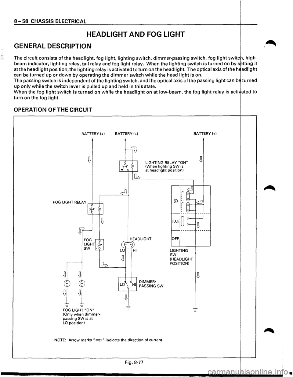
HEADLIGHT AND FOG LIGHT
GENERAL DESCRIPTION
The circuit consists of the headlight, fog light, lighting switch, dimmer·passing switch, fog light switc~, high
beam indicator,
lighting relay, tail relay and fog light relay. When the lighting switch is turned on by s~tting it
at the headlight position, the lighting relay is activated to turn on the headlight. The optical axis oft he hE ad light
can be turned up or down by operating the dimmer switch while the head light is on.
The passing switch is independent
of the lighting switch, and the optical axis ofthe passing light can bE turned
up only while the switch lever is pulled up and held in this state.
When the fog
light switch is turned on while the headlight on at low-beam, the fog light relay is acti ated to
turn on the fog light.
OPERATION OF THE CIRCUIT
BATTERY(+)
FOG LIGHT RELAY .--*-----1--,
1.~---g I
~
Wr
FOG rG LIGHT! '!r_., SW ,
FOG LIGHT "ON" (Only when dimmer• passing SW is at LO position) BATTERY(+)
BATTERY(+)
h~
I.A ~I
LIGHTING RELAY "ON" (When lighting SW is
ICb
at
headlight position)
HEADLIGHT
~· LO-HI
I
DIMMER• LO HI PASSING SW
I
.-~ ~J I I
I I
§D ~_. o ¢:!]
~-~ bt I I I I
I I 0 r--~: _____ ------
o;[X]E 0 o----~
r----------------
OFF
LIGHTING sw (HEADLIGHT
POSITION)
NOTE:
Arrow marks "c::::::>" indicate the direction of current
Fig. 8-77
J •
Page 1249 of 1928
::!! CQ 00 I ....... 00
(
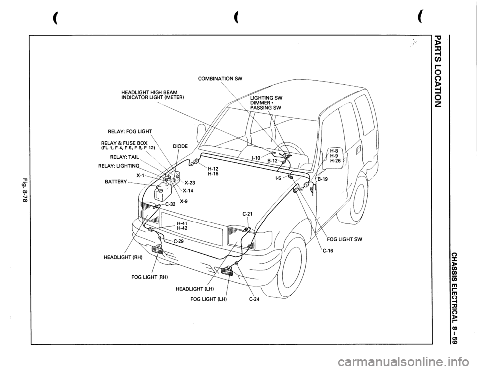
HEADLIGHT
HIGH
BEAM
INDICATOR
LIGHT
(METER)
RELAY:
FOG
LIGHT
RELAY
& FUSE
BOX
(FL-1,
F-4,
F-5, F-8,
F-12)
RELAY:
TAIL
"' "
.
RELAY:
LIGHTING
'"~
'
HEADLIGHT
(RH) FOG
LIGHT
(RH)
(
COMBINATION
SW
"',,,
HEADLIGHT
(LH)
!,--
FOG
LIGHTSW
C-16
(
;g ~ r-0 0 ~ 0 2
(') :I: )II (I)
(I) c;; m rm ~ ::a 0 )> r-eo I m
Page 1250 of 1928
![ISUZU TROOPER 1995 Workshop Manual (")
co
ill
~ (!]
11t
-
I
z
88
::0
iii
en
,
(")
0
5:
~ [I].,.
30B
~~
m
+
c
n
~ciJ~I~~
=i
:I:
FRT
FOG
LIGHT -
LH
)>
r;:;-n
11:::-1
0.85
v
f-1
..
c
(J)
0.56
.r--](/img/61/57183/w960_57183-1249.png "ISUZU TROOPER 1995 Workshop Manual (\")
co
ill
~ (!]
11t
-
I
z
88
::0
iii
en
,
(\")
0
5:
~ [I].,.
30B
~~
m
+
c
n
~ciJ~I~~
=i
:I:
FRT
FOG
LIGHT -
LH
)>
r;:;-n
11:::-1
0.85
v
f-1
..
c
(J)
0.56
.r--")
('")
co
ill
~ (!]
11t
-
I
z
88
::0
iii
en
,
('")
0
5:
~ [I].,.
30B
~~
m
+
c
n
~ciJ~I~~
=i
:I:
FRT
FOG
LIGHT -
LH
)>
r;:;-n
11:::-1
0.85
v
f'-1
..
c
(J)
0.56
.r---
!!!
(J)
,
-)>
Cii
0.56
,..,..,
~
,.....,
I
lo
.,,
G)
m
~
g~
.....
::0
r-
or-
"'
!:-<
.. _
m
., ..
;:
)>
FRT
FOG
LIGHT
SW
J:
:e
n
....
z
s
-1
ILLUMINA TlON
0.5
RIG
J~~~ll~
0.85
G/R
CONTROLLER(3)
o
• RELAY;TAIL(4)
5W
~
::0
(TO PAGE
8-791
(TO PAGE
8-78)
:;;
n
.,
0.5Y/G
0.5Y/G
do
)>
~ ;;;
r-
-
0.85R,IL
:;:
2
~
..
w
!>
OJ
-;::
ill
8~
HIGH
BEAM
INDICATOR
j1!
~~
(METER
I
z:: ~m ~~ "'"' ~:;;
~~
~I
I
~~w
l.
RELAY ;
LIGHTING
0.85Y
.. ;::
fG1
~
...
3R,IB
3W
!W
-
~-
00 I
~o-J...I
u:::J
u;
Lll;;;
I
11-1
1-11
~I
I
'!> -u::.J-
---
1.25W
..
-
-
IJ -<
HEAD
LIGHT
-RH
~
e
1.25
R1Y
~
~
w
-
I~
ANTI
THEfT
0.3V/R
!
O.!V/R
RELAY;
CORNERING(11
CONTROI.LER(181
(TO PAGE 8-1081
(TO PAGE 8-2721
.. w
Of;
I
., .. I
ill
O.SR,IB
I
s;: ~
0.56
~I
; I
I ! I
I
I
I~
~
;=
~
0.3G
ILLUMINATION
LIGHTS
(TO PAGE
8-781
)
)
)
•
Page 1252 of 1928
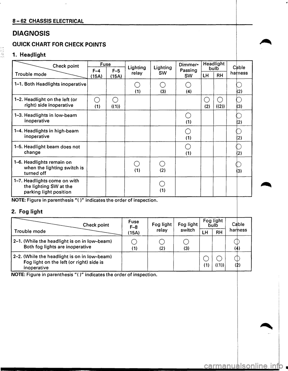
8-62 CHASSIS ELECTRICAL
DIAGNOSIS
QUICK CHART FOR CHECK POINTS ~ )-; '. ·'·• 1. Heaplight 1:·
~
Fuse Lighting Lighting Dimmer• Headlight c ~ble Passing bulb F-4
F-5 relay sw ha ness
T
(15A) (15A) sw LH RH
1-1. Both Headlights inoperative 0 0 0 b (1) (3) (4) 2)
1-2. Headlight on
the left (or 0 0 0
0 b right) side inoperative (1) ((1)) (2) ((2)) 3)
1-3. Headlights in low-beam 0 b inoperative (1) 2)
1-4. Headlights in high-beam 0 b inoperative
(1) 2)
1-5. Headlight beam does not 0 p
change (1) 2)
1-6. Headlights remain on 0 0 b when the lighting switch is
( 1) (2) 3) turned off
1-7. Headlights come on with 0 ~ the lighting SW at the
parking light position (1)
NOTE: Figure in parenthesis"( )" indicates the order of inspection.
2. Fog light
~
Fuse
Fog light Fog light Fog light Cc ble F-8 bulb
(15A) relay switch LH RH har ness Tr
2-1. (While the headlight is on in low-beam) 0 0 0 c ~ Both
fog lights are inoperative (1) (2) (3) ( )
2-2. (While the headlight is
on in low-beam) 0 0 CD Fog light on the left (or right) side is
( 1) ( ( 1)) ( ) inoperative
NOTE: Figure
in parenthesis"()" indicates the order of inspection.
~ -'
..
Page 1255 of 1928
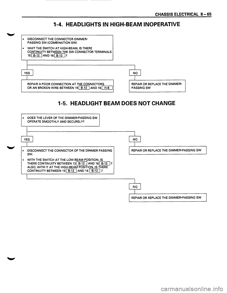
CHASSIS ELECTRICAL 8 .... 65
1-4. HEADLIGHTS IN HIGH-BEAM INOPERATIVE
• DISCONNECT THE CONNECTOR DIMMER•
PASSING SW (COMBINATION SWl
• WHIT THE SWITCH AT HIGH-BEAM, IS THERE
CONTINUITY BETWEEN THE SW CONNECTOR TERMINALS
15~AND16~7
I
I I
YES I NO I
I I
REPAIR A POOR CONNECTION AT THE CONNECTORS REPAIR OR REPLACE THE DIMMER•
OR AN BROKEN WIRE BETWEEN 15[[]IJAND 16[Jf[J PASSING SW
1-5. HEADLIGHT BEAM DOES NOT CHANGE
• DOES THE LEVER OF THE DIMMER•PASSING SW
OPERATE SMOOTHLY AND SECURELY?
I
I I
YES I
I NO I
I I
• DISCONNECT THE CONNECTOR OF THE DIMMER PASSING I REPAIR OR REPLACE THE DIMMER•PASSING sw J sw.
• WITH THE SWITCH AT THE LOW-BEAM POSITION, IS THERE CONTINUITY BETWEEN 13[[g] AND 16(]]U 1 ALSO, WITH IT AT THE HIGH-BEAM POSITION, IS THERE CONTINUITY BETWEEN 15(]]UAND 16 []}[) 1
I
l
I NO I
I
l REPAIR OR REPLACE THE DIMMER•PASSING SW J
Page 1261 of 1928
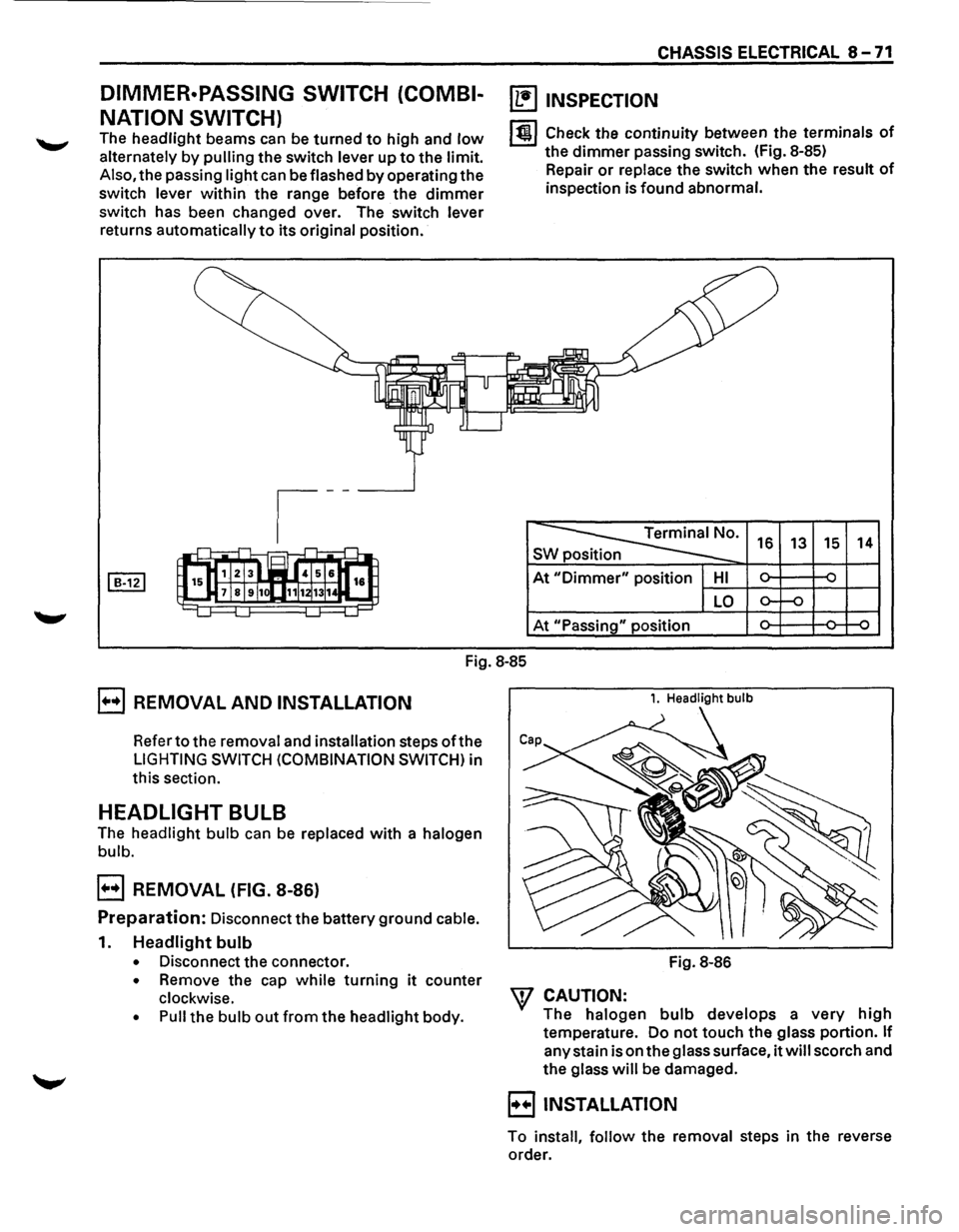
DIMMER·PASSING SWITCH (COMBI
NATION SWITCH)
The headlight beams can be turned to high and low
alternately by pulling the switch lever up to the limit.
Also, the passing light can be flashed by operating the
switch lever within the range before the dimmer
switch has been changed over. The switch lever
returns automatically to its original position.
CHASSIS ELECTRICAL 8 -71
~ INSPECTION
lt!l Check the continuity between the terminals of
the dimmer passing switch. (Fig. 8-85)
Repair
or replace the switch when the result of
inspection is found abnormal.
~· s 16 13 15 14
At "Dimmer" position HI ~ ~ -
LO o-f-o
At "Passing" position ~ ~ ~
Fig.
8-85
E] REMOVAL AND INSTALLATION
Refer to the removal and installation steps oft he
LIGHTING SWITCH (COMBINATION SWITCH) in
this section.
HEADLIGHT BULB
The headlight bulb can be replaced with a halogen
bulb.
E] REMOVAL (FIG. 8-86)
Preparation: Disconnect the battery ground cable.
1. Headlight bulb
• Disconnect the connector.
• Remove the cap while turning it counter
clockwise.
• Pull the bulb out from the headlight body.
1. Headlight bulb
Fig. 8-86
W CAUTION:
The halogen bulb develops a very high
temperature. Do not touch the glass portion. If
any stain is on the glass surface, it will scorch and
the glass will be damaged.
B INSTALLATION
To install, follow the removal steps in the reverse
order.
Page 1507 of 1928
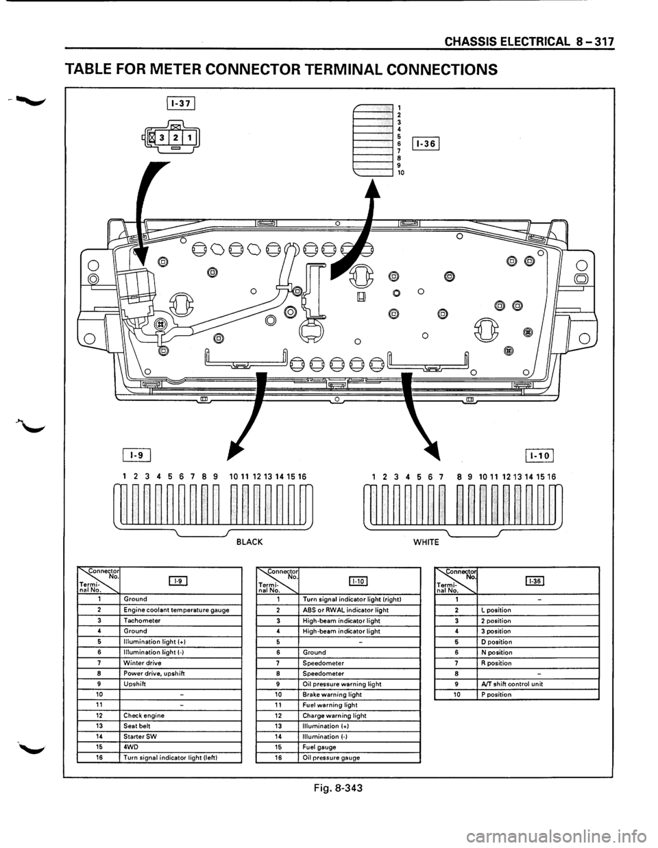
CHASSIS ELECTRICAL 8-317
TABLE FOR METER CONNECTOR TERMINAL CONNECTIONS
~-""""""', 1----""'12 1----""'1! 6 1----l 6 [Iill
1----""'1 ~ 9 1---""'l,o
®
0 0
0
® @
0 0 ~
~m© © © © ©'--m ~~0
0 !III
1 2 3 4 5 6 7 8 9 1011 1213141516 1 2 3 4 56 7 8 9 10111213141516
w~~~~~~~~ ~~~~~~m rn~~~~~~ ~~nn~~m
~ I J BLACK WHITE
~r o. DTI -na No. ~
. IJJ:Q] -
. ~ [ill] . -. 1 Ground 1 Turn
signal indicator light (right)
1 -2 Engine coolant temperature gauge 2 ABS or RWAL indicator light 2 L
position
3 Tachometer 3 High-beam indicator light 3 2 position 4
Ground
4 High-beam
indicator light 4 3 position 6 Illumination light (+I 5 -5 D position
6 Illumination light(-) 6 Ground 6 N position 7 Winter drive 7 Speedometer 7 R position 8 Power drive, upshift 8 Speedometer 8 -9 Upshift 9 Oil pressure warning light 9 AfT shift control unit 10 -10 Brake warning light 10 P position 11 -11 Fuel warning light 12 Check engine 12 Charge warning light 13 Seat belt 13 Illumination (+) 14 StarterSW 14 Illumination (-) 15 4WD 15 Fuel gauge 16 Turn signal indicator light (left) 16 Oil pressure gauge
Fig. 8-343