lock ISUZU TROOPER 1995 Workshop Manual
[x] Cancel search | Manufacturer: ISUZU, Model Year: 1995, Model line: TROOPER, Model: ISUZU TROOPER 1995Pages: 1928
Page 3 of 1928
•:1
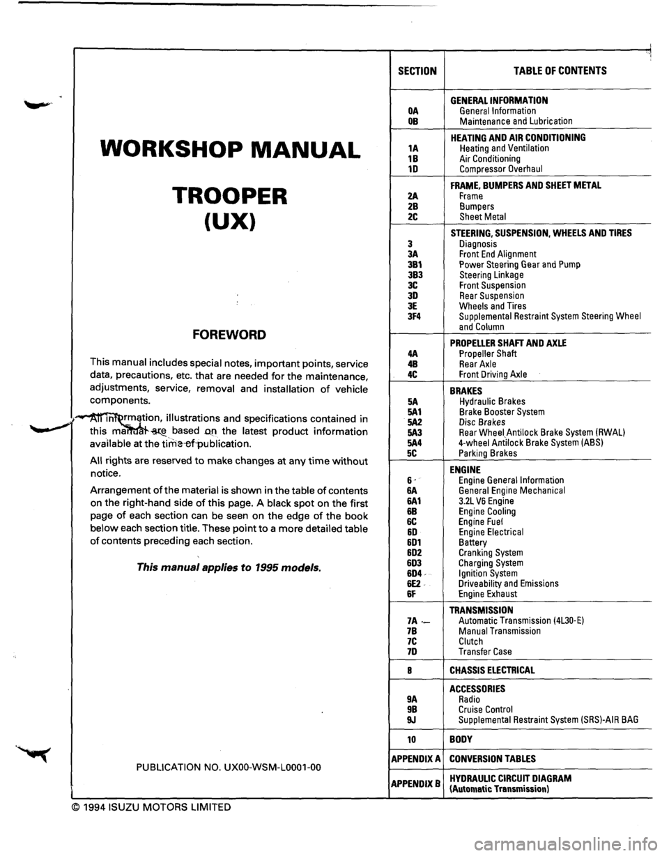
SECTION TABLE OF CONTENTS
. GENERAL INFORMATION OA General Information OB Maintenance and Lubrication
WORKSHOP MANUAL
HEATING AND AIR CONDITIONING 1A Heating and Ventilation
1B Air Conditioning 1D Compressor Overhaul
TROOPER
FRAME, BUMPERS AND SHEET METAL
2A Frame 2B Bumpers
(UX) 2C Sheet Metal
STEERING, SUSPENSION, WHEELS AND TIRES
3 Diagnosis 3A Front End Alignment 3B1 Power Steering Gear and Pump 3B3 Steering Linkage 3C Front Suspension 3D Rear Suspension 3E Wheels and Tires 3F4 Supplemental Restraint System Steering Wheel
FOREWORD and Column
PROPELLER SHAFT AND AXLE 4A Propeller Shaft This manual includes special notes, important points, service 4B Rear Axle
data, precautions, etc. that are needed for the maintenance, 4C Front Driving Axle
adjustments, service, removal and installation of vehicle BRAKES components. 5A Hydraulic Brakes
·~ m rmation, illustrations and specifications contained in 5A1 Brake Booster System
.. _,. 5A2 Disc Brakes ~ this ma. ~-based D.fl the latest product information 5A3 Rear Wheei_Antilock Brake System (RWAL)
available at the tirrHHrl·publication. 5A4 4-wheel Antilock Brake System (ABS)
5C Parking Brakes All rights are reserved to make changes at any time without ENGINE notice. 6· Engine General Information Arrangement of the material is shown in the table of contents &A General Engine Mechanical
on the right-hand side of this page. A black spot on the first 6A1 3.2L VB Engine
page of each section can be seen on the edge of the book &B Engine Cooling
6C Engine Fuel below each section title. These point to a more detailed table &D Engine Electrical of contents preceding each section. 6D1 Battery 6D2 Cranking System
This manual applies to 1995 models. 6D3 Charging System 6D4-Ignition System 6E2. Driveability and Emissions 6F Engine Exhaust
TRANSMISSION 7A-Automatic Transmission (4L30·E) 7B Manual Transmission 7C Clutch 7D Transfer Case
8 CHASSIS ELECTRICAL
ACCESSORIES 9A Radio 9B Cruise Control 9J Supplemental Restraint System (SRS)-AIR BAG
10 BODY
APPENDIX A CONVERSION TABLES PUBLICATION NO. UXOO-WSM-L0001-00
APPENDIXB HYDRAULIC CIRCUIT DIAGRAM (Automatic Transmission)
© 1994 ISUZU MOTORS LIMITED
Page 5 of 1928
GENERAL INFORMATION OA-1
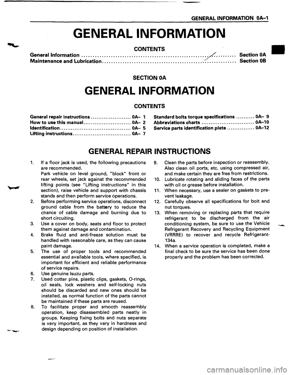
GENERAL INFORMATION
CONTENTS
General Information ........................................................ /.. . . . . . . . . Section OA / Maintenance and Lubrication ............................................. ~·. . . . . . . . . . . . . Section 08
SECTION OA
GENERAL INFORMATION
CONTENTS
General repair instructions ...................... OA-1 Standard bolts torque
specifications .......... OA-9
How to use this manual. ......................... OA-2 Abbreviations
charts ............................. OA-10
Identification
....................................... OA-5 Service
parts identification plate ............... OA-12
Lifting instructions ................................ OA-7
GENERAL REPAIR INSTRUCTIONS
1. If a floor jack is used, the following precautions
are recommended.
Park
vehicle on level ground, "block" front or
rear wheels, set jack against the recommended
lifting points (see "Lifting instructions" in this
section), raise
vehicle and support with chassis
stands and then perform service operations.
2. Before performing service operations, disconnect
ground
cable from the battery to reduce the
chance
of cable damage and burning due to
short circuiting.
3. Use a cover on body, seats and floor to protect
them against damage and contamination.
4. Brake fluid and anti-freeze solution must be
handled with reasonable care, as they can cause
paint damage.
5. The use of proper tools and recommended
essential and available tools, where specified, is
important for efficient and reliable performance
of service repairs.
6. Use genuine lsuzu parts.
7. Used cotter pins, plastic clips, gaskets, 0-rings,
oil seals, lock washers and self-locking nuts
should be discarded and new ones should be
installed, as normal function of the parts cannot
be maintained
if these parts are reused.
8. To facilitate proper and smooth reassembly
operation, keep disassembled parts neatly in
groups. Keeping fixing
bolts and nuts separate
is
very important, as they vary in hardness and
design depending on position
of installation.
9. Clean the parts before inspection or reassembly.
Also clean oil
ports, etc. using compressed air,
and make certain
they are free from restrictions.
10. Lubricate rotating and sliding faces of the parts
with oil or grease before installation.
11. When necessary, use a sealer on gaskets to pre
vent leakage.
12. Carefully observe all specifications for bolt and
nut torques.
13. When removing or replacing parts that require
refrigerant
to be discharged from the air
conditioning system, be sure
to use the Vehicle
Refrigerant Recovery and Recycling Equipment
(VRRRE) to recover and recycle Refrigerant-
134a.
14. When a service operation is completed, make a
final check to be sure the service has been done
properly and the problem has been corrected.
Page 6 of 1928
OA-2 GENERAL INFORMATION
1.
2.
3.
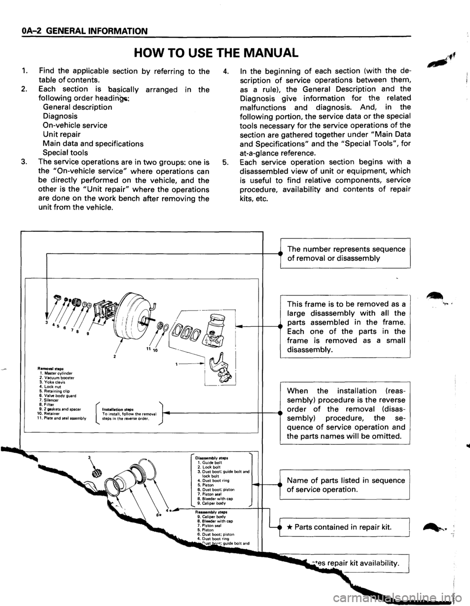
HOW TO USE THE MANUAL
Find the applicable section by referring to the
table
of contents.
4. In the beginning of each section (with the de
scription
of service operations between them,
as a rule), the General Description and the
Diagnosis give
information for the related
malfunctions and diagnosis. And, in the
following portion, the service data or the special
tools necessary
for the service operations of the
section are gathered together under
"Main Data
and
Specifications" and the "Special Tools", for
at-a-glance reference.
Each
section is basically arranged in the
following order headin~:
General description
Diagnosis
On-vehicle service
Unit repair
Main data and specifications
Special tools
The service operations are in
two groups: one is
the
"On-vehicle service" where operations can
be directly performed on the vehicle, and the
other is
the "Unit repair" where the operations
are done on the
work bench after removing the
unit
from the vehicle.
5. Each service operation section begins with a
disassembled
view of unit or equipment, which
is useful
to find relative components, service
procedure, availability and contents
of repair
kits, etc.
,..---------------------------+--e The number represents sequence of removal or disassembly
Removal steps 1. Master cylinder 2. Vacuum booster 3. Yoke clevis 4. Lock nut 5. Retaining clip 6. Valve body guard 7. Silencer 8. Filter 9. 2 gaskets and spacer 10. Retainer 11. Plate and seal assembly (
Installation steps To install, follow the remo ... al steps in the reverse order.
Disassembly steps 1. Guide bolt 2. Lock bolt 3. Dust boot; guide bolt and lock bolt 4. Dust boot ring
5. Piston 6. Dust boot; piston
7. Piston seal B. Bleeder with cap 9. Caliper body
Reassembly steps 9. Caliper body 8. Bleeder with cap 7. Piston seal 5. Piston 6. Dust boot; piston 4. Dust boot ring nust •"·•t; guide bolt and
This frame is to be removed as a
large disassembly
with all the
parts assembled in the frame.
Each one
of the parts in the
frame is removed as a small
disassembly.
When the installation (reas
sembly) procedure is the reverse
order of the removal (disas
sembly) procedure, the se
quence
of service operation and
the parts names
will be omitted.
Name
of parts listed in sequence
of service operation.
* Parts contained in repair kit.
•
-
.,... .
Page 7 of 1928
6.
.. .......,
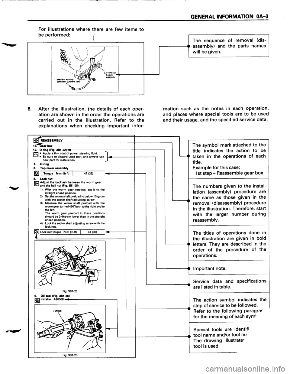
For illustrations where there are few items to
be performed: (
2. :~~~f.' .. ':.. ._----4-----l IINmbly
After the illustration, the details of each oper
ation are
shown in the order the operations are
carried
out in the illustration. Refer to the
explanations
when checking important infor-
r box
GENERAL INFORMATION OA-3
The sequence of removal (dis
assembly) and the parts names
will be given.
mation such as the notes in each operation,
and places
where special tools are to be used
and
their usage, and the specified service data.
12. o-rtng (Fig. 381-22:}-ooolt----------------1---------. hi • Apply a thin coat of power steering fluid. ~ • Be sure to discard used part, and always use
The symbol mark attached to the
title indicates the action
to be
taken in the operations
of each
title. new part for installation. 7. 0-rlng 8. Top cover assembly
~ Torque N·m Ub·ftl I 47 (351
5. Lock nut Eel Adjust the backlash between the worm gear 11:1 and the ball nut (Fig. 381-251. 11 With the worm gear rotating, set it to the
straight ahead position.
21 Setthe worm shaft preload to below 10kg-cm with the sector shaft adjusting screw. 31 Measure the worm shaft preload with the
worm gear turned 450' both to the right and to
the left. The worm gear preload in these positions should be 2-4kg-cm lower than in the straight
ahead position.
41 lock the sector shaft adjusting screw with the lock nut.
lock nut torque N·m Ub·ftl
Fig. 381-25 4. Ollae•l (Fig. 381-281
41 (301
~Installer: J-26508 -'------------,
Example for this case;
1st
step-Reassemble gear box
The numbers given to the instal
lation (assembly) procedure are
the same
as those given in the
removal (disassembly) procedure
in the illustration. Therefore, start
with the larger number during
reassembly.
The titles
of operations done in
the
illustration are given in bold
letters. They are described in the
order
of the procedure of the
operations.
Important note.
Service data and specifications
are listed in table.
The action symbol indicates the
step
of service to be followed.
Refer
to the following paragrar·
for the meaning of each sym'
Special tools are identifi
tool name and/or tool nu
The
drawing illustrate'
tool is used.
Page 9 of 1928
IDENTIFICATION
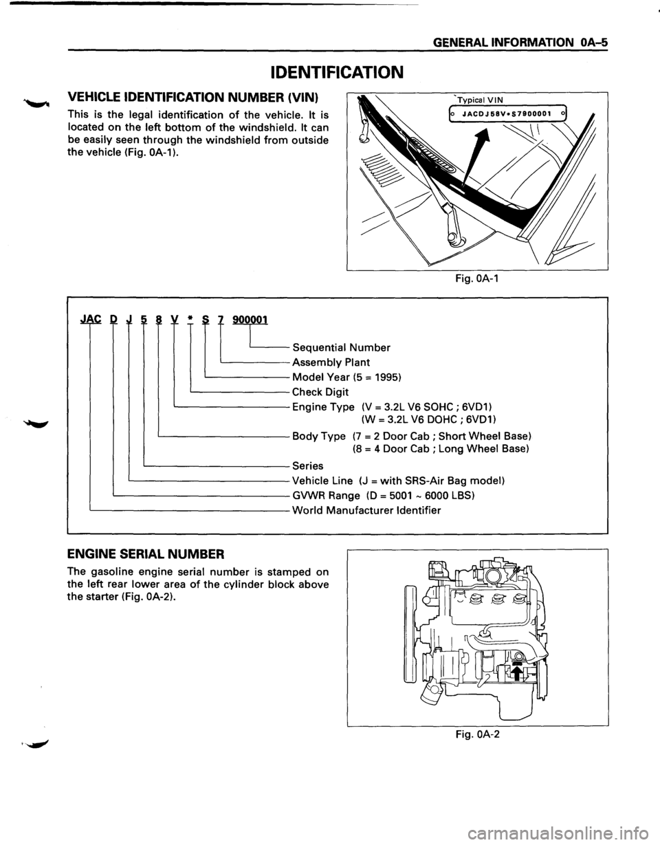
VEHICLE IDENTIFICATION NUMBER (VIN)
This is the legal identification of the vehicle. It is
located
on the left bottom of the windshield. It can
be easily seen
through the windshield from outside
the vehicle (Fig.
OA-1).
~ !~ :i ~ v * ~7L_
~Sequential Number
Assembly Plant
Model Year (5 = 1995)
Check Digit
GENERAL INFORMATION OA-5
Fig. OA-1
Engine Type (V = 3.2L V6 SOHC ; 6VD1)
(W = 3.2L V6
DOHC ; 6VD1)
Body Type
(7 = 2 Door Cab ; Short Wheel Base)
(8 = 4 Door Cab ; Long Wheel Base)
Series
Vehicle Line
(J =with SRS-Air Bag model)
GVWR Range
(0 = 5001 -6000 LBS)
World Manufacturer Identifier
ENGINE SERIAL NUMBER
The gasoline engine serial number is stamped on
the
left rear lower area of the cylinder block above
the starter (Fig. OA-2).
Fig. OA-2
Page 14 of 1928
OA-10 GENERAL INFORMATION
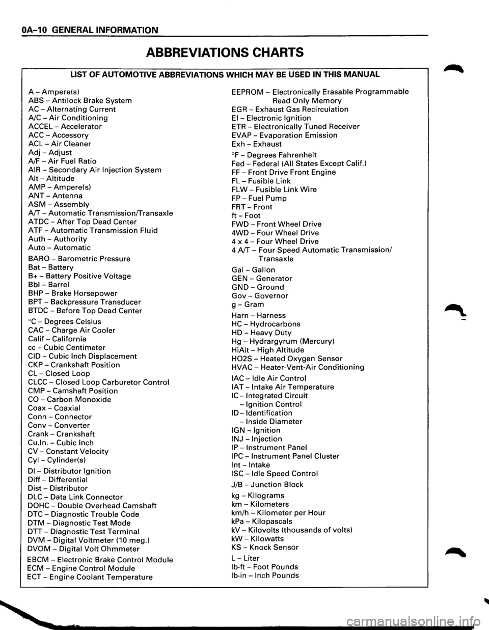
ABBREVIATIONS CHARTS
LIST OF AUTOMOTIVE ABBREVIATIONS WHICH MAY BE USED IN THIS MANUAL
A-Ampere(s)
ABS-Anti lock Brake System
AC-Alternating Current
A/C-Air Conditioning
ACCEL-Accelerator
ACC-Accessory
ACL-Air Cleaner
Adj-Adjust
A/F-Air Fuel Ratio
AIR-Secondary Air Injection System
Alt-Altitude
AMP-Ampere(s)
ANT-Antenna
ASM-Assembly
A/T-Automatic Transmission/Transaxle
ATDC-After Top Dead Center
ATF-Automatic Transmission Fluid
Auth -Authority
Auto -Automatic
BARO-Barometric Pressure
Bat -Battery
B+-Battery Positive Voltage
Bbl-Barrel
BHP-Brake Horsepower
BPT-Backpressure Transducer
BTDC-Before Top Dead Center
oc-Degrees Celsius
CAC-Charge Air Cooler
Calif-California
cc-Cubic Centimeter
CID-Cubic Inch Displacement
CKP-Crankshaft Position
CL-Closed Loop
CLCC-Closed Loop Carburetor Control
CMP-Camshaft Position
CO-Carbon Monoxide
Coax-Coaxial
Conn-Connector
Conv -Converter
Crank-Crankshaft
Cu.ln.-Cubic Inch
CV-Constant Velocity
Cyl-Cylinder(s)
Dl -Distributor Ignition
Diff-Differential
Dist-Distributor
DLC-Data Link Connector
DOHC-Double Overhead Camshaft
DTC-Diagnostic Trouble Code
DTM-Diagnostic Test Mode
DTT-Diagnostic Test Terminal
DVM-Digital Voltmeter (10 meg.)
DVOM-Digital Volt Ohmmeter
EBCM-Electronic Brake Control Module
ECM-Engine Control Module
ECT-Engine Coolant Temperature
EEPROM -Electronically Erasable Programmable
Read Only Memory
EGR-Exhaust Gas Recirculation
El-Electronic Ignition
ETR-Electronically Tuned Receiver
EVAP-Evaporation Emission
Exh-Exhaust
°F-Degrees Fahrenheit
Fed -
Federal (All States Except Calif.)
FF-Front Drive Front Engine
FL-Fusible Link
FLW-Fusible Link Wire
FP-Fuel Pump
FRT-Front
ft-Foot
FWD-Front Wheel Drive
4WD-Four Wheel Drive
4 x
4-Four Wheel Drive
4 A/T-Four Speed Automatic Transmission/
Transaxle
Gal-Gallon
GEN-Generator
GND-Ground
Gov-Governor
g-Gram
Harn -Harness
HC-Hydrocarbons
HD-Heavy Duty
Hg-Hydrargyrum (Mercury)
HiAit-High Altitude
H02S - Heated Oxygen Sensor
HVAC-Heater-Vent-Air Conditioning
lAC-Idle Air Control
IAT -Intake Air Temperature
IC-Integrated Circuit
-
Ignition Control
ID-Identification
-Inside Diameter
IGN-Ignition
INJ-Injection
IP-Instrument Panel
IPC-Instrument Panel Cluster
lnt-Intake
ISC-Idle Speed Control
J/B-Junction Block
kg -Kilograms
km-Kilometers
km/h -Kilometer per Hour
kPa-Kilopascals
kV-Kilovolts (thousands of volts)
kW-Kilowatts
KS -Knock Sensor
L-Liter
lb·ft-Foot Pounds
lb·in-Inch Pounds
Page 15 of 1928
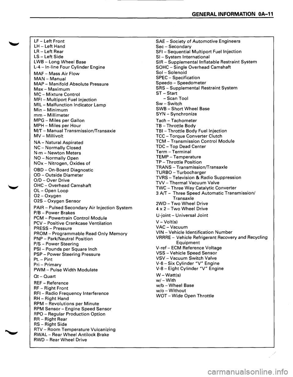
LF -Left Front
LH -Left Hand
LR-Left Rear
LS-Left Side
LWB-Long Wheel Base
L-4-In-line Four Cylinder Engine
MAF-Mass Air Flow
MAN-Manual
MAP-Manifold Absolute Pressure
Max-Maximum
MC-Mixture Control
MFI-Multipart Fuel Injection
MIL-Malfunction Indicator Lamp
Min-Minimum
mm-Millimeter
MPG-Miles per Gallon
MPH-Miles per Hour
M!f-Manual Transmission!fransaxle
MV-Millivolt
NA-Natural Aspirated
NC-Normally Closed
N·m-Newton Meters
NO-Normally Open
NOx-Nitrogen, Oxides of
OBD-On-Board Diagnostic
OD-Outside Diameter
0/D-Over Drive
OHC-Overhead Camshaft
OL-Open Loop
02-Oxygen
02S -Oxygen Sensor
PAIR-Pulsed Secondary Air Injection System
P/B-Power Brakes
PCM-Powertrain Control Module
PCV-Positive Crankcase Ventilation
PRESS-Pressure
PROM-Programmable Read Only Memory
PNP-Park/Neutral Position
P/S-Power Steering
PSI-Pounds per Square Inch
PSP-Power Steering Pressure
Pt.-Pint
Pri -Primary
PWM-Pulse Width Modulate
Ot-Quart
REF-Reference
RF -Right Front
RFI-Radio Frequency Interference
RH-Right Hand
RPM-Revolutions per Minute
RPM Sensor-Engine Speed Sensor
RPO-Regular Production Option
RR-Right Rear
RS-Right Side
RTV-Room Temperature Vulcanizing
RWAL-Rear Wheel Anti lock Brake
RWD-Rear Wheel Drive
GENERAL INFORMATION OA-11
SAE -Society of Automotive Engineers
Sec-Secondary
SFI-Sequential Multipart Fuel Injection
Sl-System International
SIR-Supplemental Inflatable Restraint System
SOHC-Single Overhead Camshaft
Sol -Solenoid
SPEC -Specification
Speedo -Speedometer
SRS-Supplemental Restraint System
ST-Start
-Scan Tool
Sw-Switch
SWB-Short Wheel Base
SYN-Synchronize
Tach-Tachometer
TB
-Throttle Body
TBI-Throttle Body Fuel Injection
TCC-Torque Converter Clutch
TCM-Transmission Control Module
TDC-Top Dead Center
Term-Terminal
TEMP-Temperature
TP-Throttle Position
TRANS-Transmission!fransaxle
TURBO-Turbocharger
TVRS-Television & Radio Suppression
TVV-Thermal Vacuum Valve
TWC-Three Way Catalytic Converter
3
AfT-Three Speed Automatic Transmission/
Transaxle
2WD-Two Wheel Drive
4 x
2-Two Wheel Drive
U-joint-Universal Joint
V-Volt(s)
VAC-Vacuum
VIN-Vehicle Identification Number
VRRRE -Vehicle Refrigerant Recovery and Recycling
Equipment
V-ref-ECM Reference Voltage
VSS-Vehicle Speed Sensor
VSV-Vacuum Switch Valve
V-6-Six Cylinder "V" Engine
V-8-Eight Cylinder "V" Engine
W-Watt(s)
w/-With
w/b -Wheel Base
w/o -Without
WOT-Wide Open Throttle
Page 17 of 1928
MAINTENANCE AND LUBRICATION OB-1
SECTION 08
MAINTENANCE AND LUBRICATION
CONTENTS
Maintenance Schedule List . . . . . . . . . . . . 08-1
Explanation of Complete Vehicle
Mai-ntenance Schedule . . . . . . . . . . . . . . 08-4
Recommended
Fluids and Lubricants . . . . 08-8
Lubricant Viscosity Chart ............... 08-9
Recommended Liquid Gasket
........... 08-11
Recommended Thread Locking Agents ... 08-11
Maintenance Service Data .............. 08-12
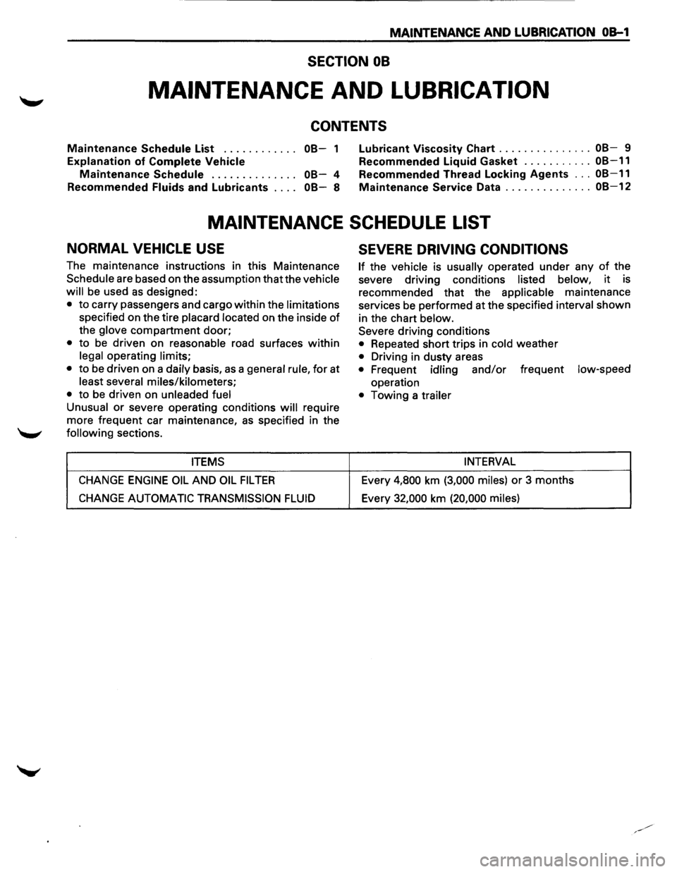
MAINTENANCE SCHEDULE LIST
NORMAL VEHICLE USE
The maintenance instructions in this Maintenance
Schedule are based on the assumption that the vehicle
will
be used as designed:
• to carry passengers and cargo within the limitations
specified on the tire placard located on the inside of
the glove compartment door;
• to be driven on reasonable road surfaces within
legal operating limits;
•
to be driven on a daily basis, as a general rule, for at
least several miles/kilometers;
•
to be driven on unleaded fuel
Unusual
or severe operating conditions will require
more frequent car maintenance,
as specified in the
following sections.
ITEMS
CHANGE ENGINE OIL AND OIL FIL TEA
CHANGE AUTOMATIC TRANSMISSION FLUID
SEVERE DRIVING CONDITIONS
If the vehicle is usually operated under any of the
severe driving conditions
listed below, it is
recommended that the
applicable maintenance
services be performed at the specified
interval shown
in the chart
below.
Severe driving conditions
• Repeated short trips in cold weather
• Driving in dusty areas
• Frequent idling and/or frequent low-speed
operation
• Towing a trailer
INTERVAL
Every 4,800 km (3,000 miles) or 3 months
Every
32,000 km (20,000 miles)
Page 21 of 1928
FLUID LEVEL CHECK
A fluid loss in any system (except windshield
washer) may indicate a problem. Repair the system
at once.
Engine
oil level -Check level and add if
necessary. The best time to check the engine oil
level is
when the oil is warm. After stopping the
engine with the vehicle on a level surface, wait a
few minutes for the oil to drain back to the oil pan.
Pull
out the oil level indicator (dipstick). Wipe it
clean and push the oil level indicator back down all
the
way. Pull out the oil level indicator, keeping the
tip down, and look at the oil level on it.
Add oil, if needed, to keep the oil level above
the
"ADD" mark and between the "ADD" and
"FULL" marks in the operating range area. Avoid
overfilling the engine since this may cause engine
damage. Push
the oil level indicator back down all
the
way after taking the reading.
If you check the oil level when the oil is cold, do
not run the engine first. The cold oil will not drain
back
to the pan fast enough to give a true oil level.
Engine coolant level and condition -Check
engine coolant level in the coolant reservoir and
add engine
coolant if necessary. Inspect the engine
coolant and replace it if dirty or rusty.
Windshield washer fluid level -Check washer
fluid level in reservoir and add if necessary.
Power steering system reservoir level-Check
and keep at
proper level.
Brake master cylinder reservoir level -Check
fluid. Keep fluid at proper level. A low fluid level
can indicate
worn disc brake pads which may need
to be serviced.
Hydraulic clutch system -Check fluid l~vel in
the reservoir.
Add fluid as required.
Battery fluid level -Check fluid level in the
battery.
FLUID LEAK CHECK
Check for fuel, water, oil or other fluid leaks by
looking at the surface beneath the vehicle after it
has been parked for a while. Water dripping from
the air conditioning system after use is normal. If
you notice gasoline fumes or fluid at any time,
locate the source and correct it at once.
ENGINE OIL AND OIL FILTER
REPLACEMENT
Always use API SE, SF, SG, SH or ILSAC GF-1
quality oils of the proper viscosity.
When choosing an oil, consider the range of
temperatures the car will be operated in before the
next oil change. Then, select the recommended oil
viscosity
from the chart (Fig. OB-1).
Always change the oil and the oil filter as soon as
possible after driving in a dust storm.
MAINTENANCE AND LUBRICATION OB-5
ENGINE COOLING SYSTEM INSPECTION
Inspect coolant/anti-freeze. If coolant is dirty or
rusty, drain, flush and refill with new coolant. Keep
coolant at the proper mixture for proper freeze
protection,
corrosion inhibitor level and best engine
operating temperature.
Inspect hoses and replace if
cracked, swollen or deteriorated. Tighten hose
clamps if equipped with screw-type clamps. Clean
outside of radiator and air conditioning condenser.
Wash
filler cap and neck. To help ensure proper
operation, a pressure test of both the cooling
system and cap is also recommended.
EXHAUST SYSTEM INSPECTION
Visually inspect the exhaust pipes, muffler, heat
shields and hangers
for cracks, deterioration, or
damage.
Be alert to any changes in the sound of the exhaust
system
or any smell of fumes. These are signs the
system may be leaking or overheating. Repair the
system at once,
if these conditions exist. (See also
"Engine Exhaust Gas Safety" and "Three Way
Catalytic Converter" in Owner's manual.)
FUEL CAP, FUEL LINES, AND FUEL TANK
INSPECTION
Inspect the fuel tank, the fuel cap and the fuel lines
every
60,000 miles (96,000 km) for damage which
could cause leakage.
Inspect the fuel cap and the gasket for correct sealing
and physical damage. Replace any damaged parts.
DRIVE BELT INSPECTION
Check the belts driving the steering oil pump, the air
conditioning compressor, and the generator
for
cracks, fraying, wear, and correct tension every 30,000
miles (48,000 km). Adjust or replace as necessary.
WHEEL ALIGNMENT, BALANCE AND
TIRES OPERATION
Uneven or abnormal tire wear, or a pull right or left
on a straight and level road may show the need for
a wheel alignment. A vibration of the steering
wheel or seat at normal highway speeds means a
wheel balancing is needed. Check tire pressure
when the tires are "cold" (include the spare).
Maintain pressure as shown in the tire placard,
which is located on the driver's door lock pillar.
STEERING SYSTEM OPERATION
Be alert for any changes in steering action. An
inspection
or service is needed when the steering
wheel is harder
to turn or has too much free play, or
if there are unusual sounds when turning or parking.
Page 22 of 1928
OB-6 MAINTENANCE AND LUBRICATION
BRAKE SYSTEMS OPERATION
Watch for the "BRAKE" light coming on. Other
signs of possible brake trouble are such things as
repeated pulling to one side when braking, unusual
sounds
when braking or between brake
applications,
or increased brake pedal travel. If you
note one of these conditions, repair the system at
once.
For convenience, the
following should be done
when wheels are removed for rotation: Inspect lines
and hoses
for proper hookup, bindings, leaks, crack,
chafing etc.
Inspect disc brake pads for wear and
rotors
for surface condition.
Inspect other brake parts, including parking brake
drums, linings etc., at the same time. Check parking
brake adjustment.
Inspect brakes more often if habit or
conditions
result in frequent braking.
PARKING BRAKE AND TRANSMISSION
PARK MECHANISM OPERATION
Park on a fairly steep hill and hold the vehicle with
the parking brake only. This checks holding ability.
On
automatic transmission vehicles, shifting from
"P" position to the other positions cannot be made
unless
the brake pedal is depressed when the key
switch is in
"ON" position or the engine running.
WARNING
•
Before checking starter safety switch
operation below,
be sure to have enough
room around the
vehicle. Then firmly apply
both the parking brake and the regular brake.
Do not
use the accelerator pedal. If the engine
starts, be ready
to turn off the key promptly.
Take these precautions because the vehicle
could move
without warning and possibly
cause personal injury
or property damage.
STARTER SAFETY SWITCH OPERATION
(AUTOMATIC TRANSMISSION)
Check by trying to start the engine in each gear
while setting the parking brake and the foot brake.
The starter
should crank only in "P" (Park) or "N"
(Neutral).
STARTER SAFETY SWITCH OPERATION
(MANUAL TRANSMISSION)
To check, place the shift lever in "Neutral", push
the clutch pedal halfway and try to start. The starter
should not crank. The starter should crank only
when the clutch pedal is fully depressed.
ACCELERATOR LINKAGE LUBRICATION
Lubricate the accelerator pedal fulcrum pin with
chassis grease.
STEERING AND SUSPENSION
INSPECTION
Inspect front and rear suspension and steering
system
for damaged, loose or missing parts or signs
of wear. Inspect power steering lines and hoses for
proper hookup, binding, leaks, cracks, chafing, etc.
BODY AND CHASSIS LUBRICATION
Lubricate the key lock cylinders, the hood latch, the
hood and door hinges, the door check link, the
parking cable guides,
the underbody contact points,
and the linkage.
PROPELLER SHAFT INSPECTION AND
LUBRICATION
Lubricate sliding yoke and universal joints with
grease containing MOS2 (disulfide molybdenum
type grease) at the interval shown in the
Maintenance Schedule. Check for play in normal
direction of rotation of sliding yoke and universal
joints. Also check
propeller shaft flange-to-pinion
bolts for proper torque of 63 N·m (46 lb·ft) for front
and rear propeller shaft.
AUTOMATIC TRANSMISSION FLUID
INSPECTION
Check the lubricant level every 7,500 miles (12,000
km) and add lubricant
if necessary.
Under harsh operating conditions, such as constant
driving in heavy city traffic during
hot weather, or in
hilly or mountainous terrain, change the transmission
fluid and service the
sump filter after every 20,000
miles (32,000 km) of operation.
AUTO CRUISE CONTROL INSPECTION
Check to see if the clearance between cruise link and
accelerator is normal. Also check that the vacuum
hoses are routed and connected properly.
CLUTCH LINES AND HOSES INSPECTION
Check lines and hoses for proper attachment,
binding, leaks, cracks, chafing, deterioration, etc.
Any questionable parts should be replaced or
repaired at once. When abrasion or wear is evident
on lines or hoses, the cause must be corrected.
..