fuse box ISUZU TROOPER 1995 User Guide
[x] Cancel search | Manufacturer: ISUZU, Model Year: 1995, Model line: TROOPER, Model: ISUZU TROOPER 1995Pages: 1928
Page 941 of 1928
AUTOMATIC TRANSMISSION (4L30-E) 7 A-69
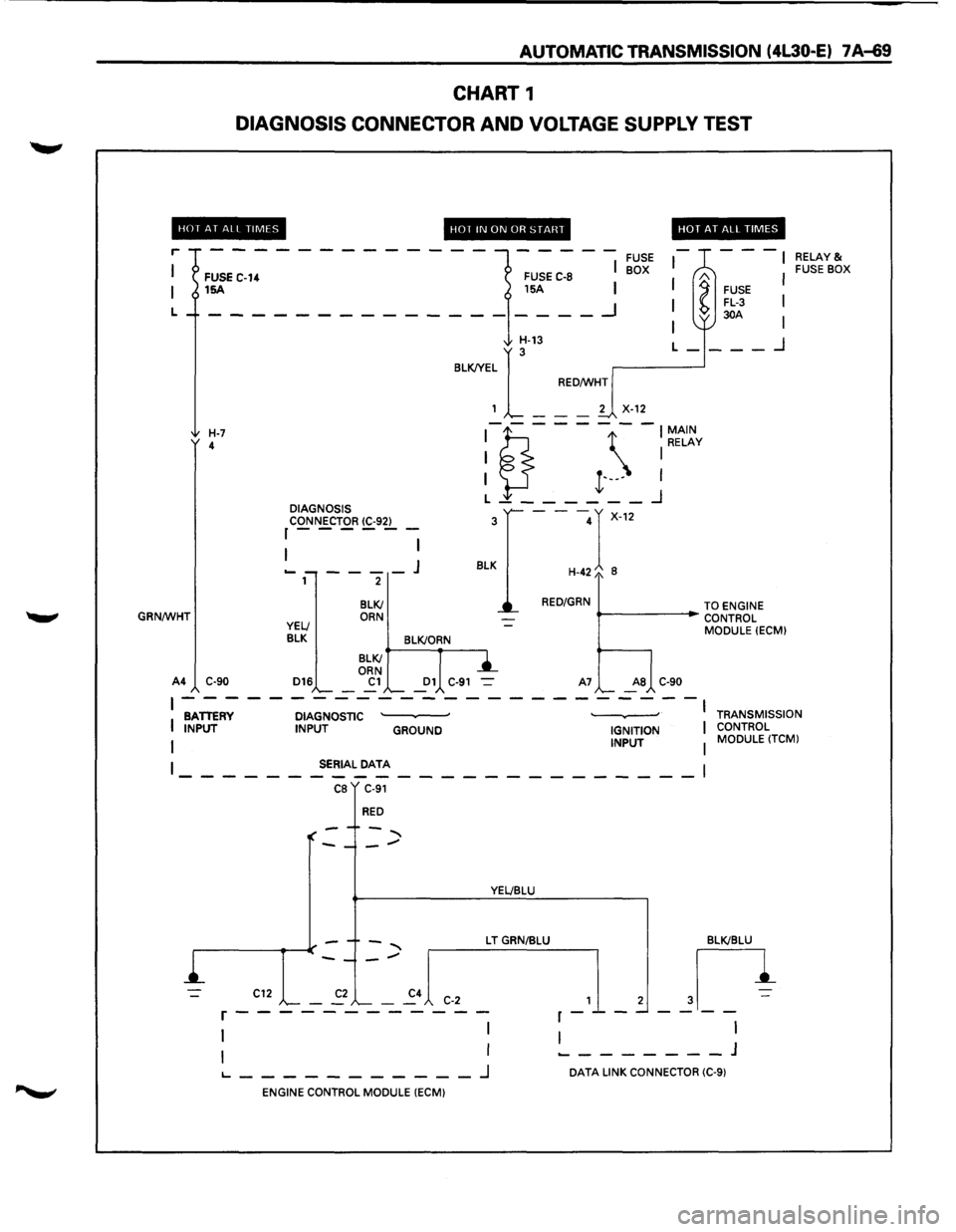
CHART 1
DIAGNOSIS CONNECTOR AND VOLTAGE SUPPLY TEST
HOf AT All TIMES
r
L
GRN/WHT
FUSE C-14 15A
H-7 4
A4 C-90 DIAGNOSIS
CONNECTOR
(C-92) r------
1 I
----J 2
BLKI ORN
HOT IN ON OR START
FUSE C-8
15A I
I
__ _I
FUSE BOX
HOT AT ALL TIMES
---
l
A FUSE FL-3 30A
I I
I
I
H-13
BLKJYEL
1
[_ --
RED/WHT
L-___ _j
2
X-12
:1?.---- -:~t~v
I }-I t·---I L _______ _j
---r-12
H-42/o 8
3
BLK
RED/GRN
""--------i~ TO ENGINE
..- CONTROL
MODULE
(ECM)
YELl
BLK BLK!ORN
D16
BLKI
ORN
Cl Dl C-91 A7 AS C-90
RELAY& FUSE BOX
~------------------------BATTERY DIAGNOSTIC · · I
I INPUT INPUT GROUND IGNITION I
I INPUT I
TRANSMISSION
CONTROL MODULE
(TCM)
I SERIAL DATA
------------------------1 CB C-91
RED
YEL/BLU
L T GRN/BLU BLKIBLU
,_1_, ~n
I I ________ J
C12 C-2 r------------
1 I
I I
1...--------_J DATA LINK CONNECTOR (C-9)
ENGINE CONTROL MODULE (ECM)
Page 962 of 1928
7 A-90 AUTOMATIC TRANSMISSION (4L30-E)
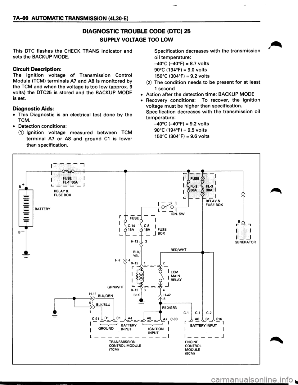
DIAGNOSTIC TROUBLE CODE (DTC) 25
SUPPLY VOLTAGE TOO LOW
This DTC flashes the CHECK TRANS indicator and
sets the BACKUP
MODE.
Specification decreases with the transmission
oil temperature:
Circuit Description:
-40°C (-40°F) = S.7 volts
90°C (194°F) = 9.0 volts
150°C (304°F) = 9.2 volts The ignition voltage of Transmission Control
Module (TCM) terminals A7 and AS is monitored by
the TCM and when the voltage is too low (approx. 9
volts) the DTC25 is stored and the BACKUP MODE
is set.
@ The condition needs to be present for at least
1 second
• Action after the detection time: BACKUP MODE
Diagnostic Aids:
• This Diagnostic is an electrical test done by the
TCM.
• Recovery conditions: To recover, the ignition
voltage must be higher than specification.
Specification decreases
with the transmission oil
temperature:
-40°C (-40°F) = 9.2 volts
90°C (194°F) = 9.5 volts
150°C (304°F) = 9.6 volts
• Detection conditions:
CD Ignition voltage measured between TCM
terminal A7 or AS and ground C1 is lower
than specification .
. · fU I
I '
f:L;~soA L., ____ J
RELAY & FUSE BOX
1--, {)-:,.--____..J BATTERY
l
T
L __ I
r
I C-14 C-8 I I 15A 15A FUSE -__ + _ j BOX
H-13t 3
H-7 'x~.~~'---7 r ]_-
GRN/WHT
BATTERY I GROUND INPUT IGNITION I INPUT I
L-----------TRANSMISSION
CONTROL MODULE
(TCM) IGN.SW.
RED/WHT
C-1 C-1 C-2
A6 B1 C16
r -;ATTERV INPUT-l
I
I l _____ j
ENGINE
CONTROL MODULE
(ECM)
I I
I-_j GENERATOR
Page 964 of 1928
7 A-92 AUTOMATIC TRANSMISSION (4L30-E)
DIAGNOSTIC TROUBLE CODE (DTC) 26
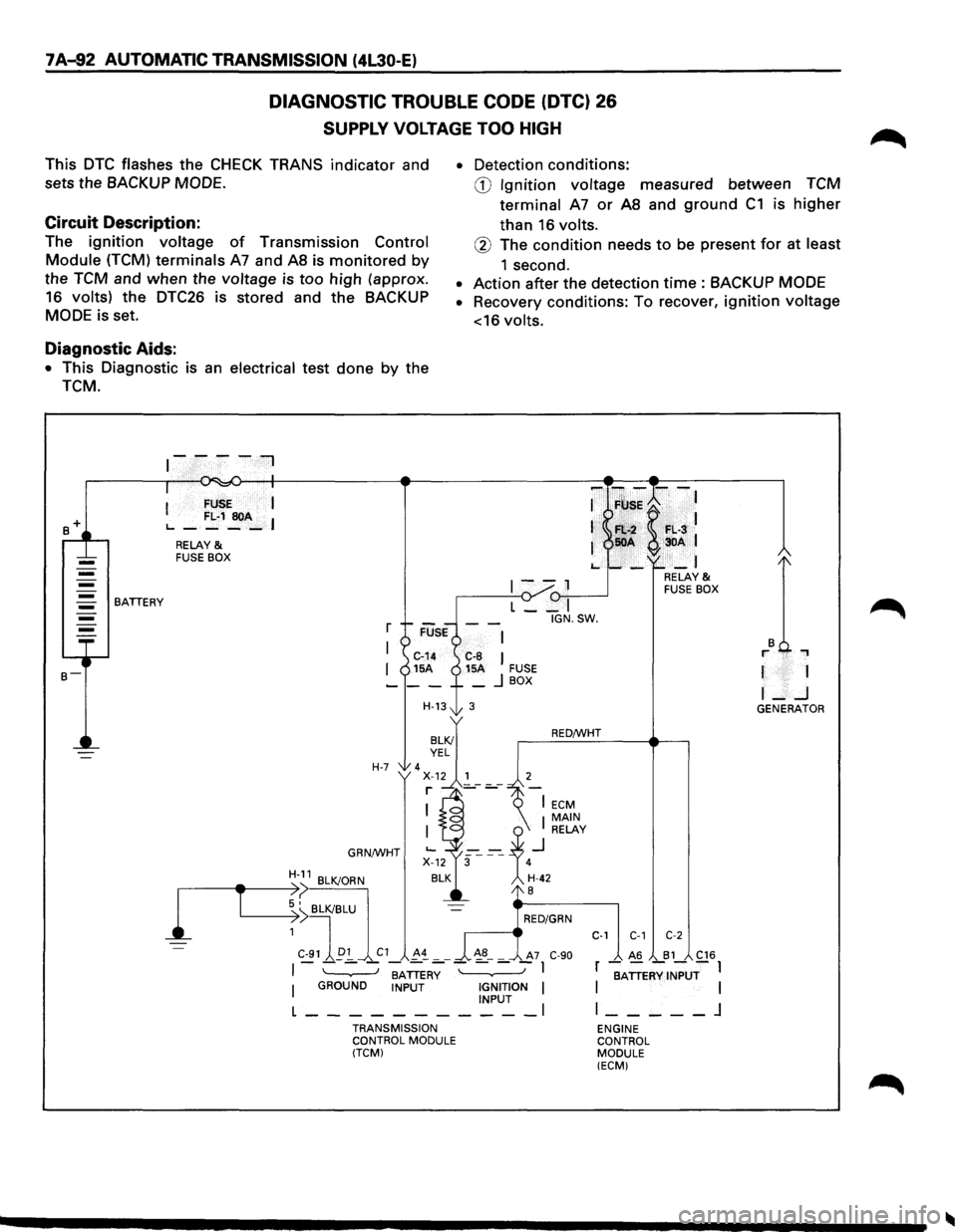
SUPPLY VOLTAGE TOO HIGH
This DTC flashes the CHECK TRANS indicator and
sets the
BACKUP MODE.
Circuit Description:
The ignition voltage of Transmission Control
Module (TCM) terminals A7 and AS is monitored by
the TCM and when the voltage is too high (approx.
16 volts) the
DTC26 is stored and the BACKUP
MODE is set.
Diagnostic Aids:
• This Diagnostic is an electrical test done by the
TCM.
BATTERY
I FUSE I
L..-FL·1~A-I
RELAY & FUSE BOX
r
I
I
H-7
GRN/WHT
H-11 BLK/ORN
• Detection conditions:
CD Ignition voltage measured between TCM
terminal
A7 or AS and ground C1 is higher
than 16 volts.
® The condition needs to be present for at least
1 second.
• Action after the detection time : BACKUP MODE
• Recovery conditions: To recover, ignition voltage
<16
volts.
-F~;K--:
Fl:.-2 F•. L·3 50A 3DA 1
-_I
1--1 (1-,,--...----J L __ I
IGN.SW.
C-8 I 15A FUSE _ j BOX
3
RED/WHT
RELAY & FUSE BOX
r 1
I-..J GENERATOR
1
,-----------e-T ~:>( BLK/BLU
~ I RED/GRN
1
C-91 ~p:!_ C1 !-~ _ _ ~8-_ A7 C-90
C-1 C-1 C-2
I - - - -BATTER~ - - - -I
I GROUND INPUT IGNITION I INPUT l ___________ l
TRANSMISSION
CONTROL MODULE
(TCM)
_ A6 _B1_ C16
r BATTERY INPUT I I I
l _____ j
ENGINE
CONTROL
MODULE (ECM)
Page 996 of 1928
7A-124 AUTOMATIC TRANSMISSION (4L30-E)
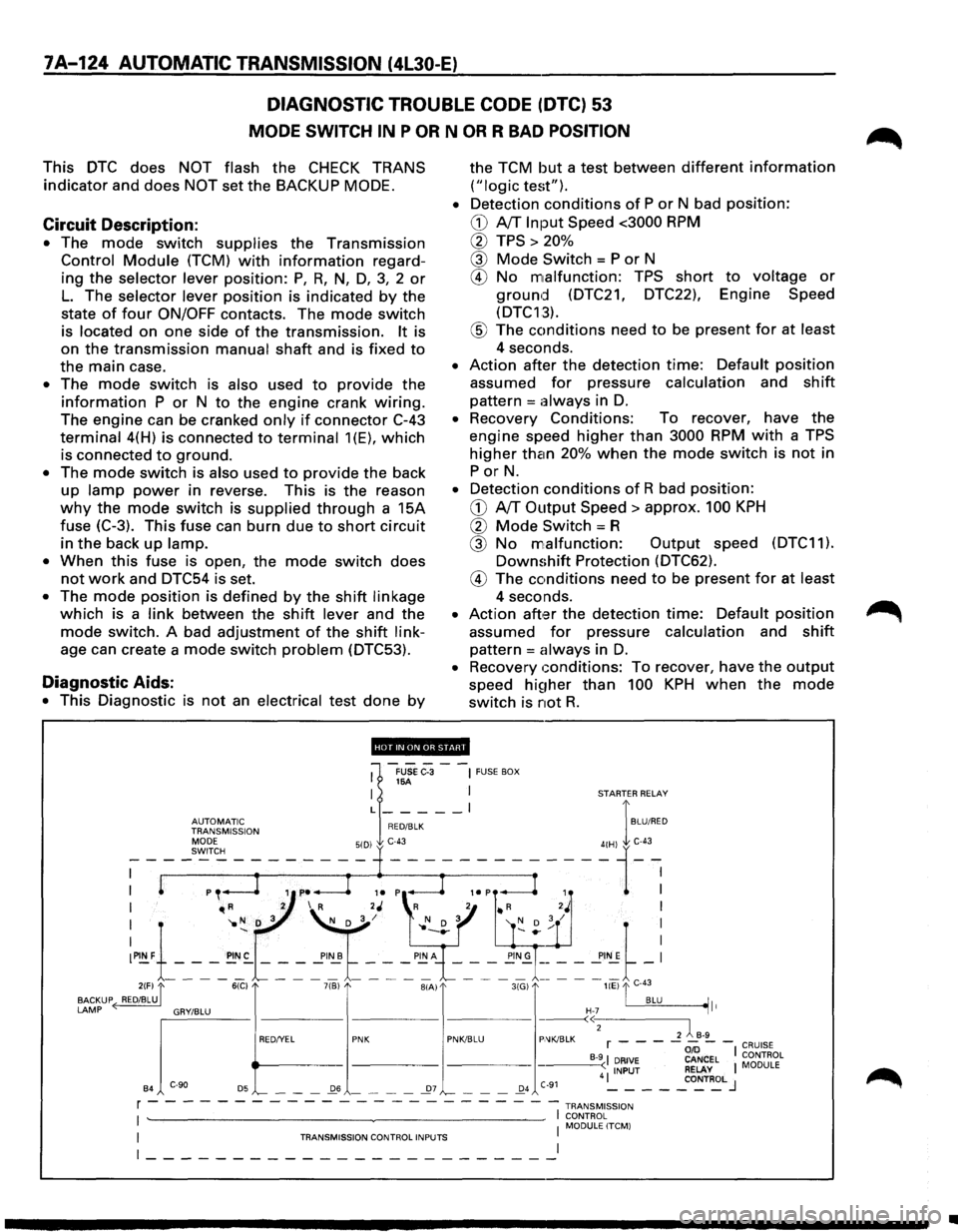
DIAGNOSTIC TROUBLE CODE (DTC) 53
MODE SWITCH IN P OR N OR R BAD POSITION
This DTC does NOT flash the CHECK TRANS
indicator and does NOT set the BACKUP MODE.
Circuit Description:
• The mode switch supplies the Transmission
Control Module (TCM) with information regard
ing
the selector lever position: P, R, N, D, 3, 2 or
L. The selector lever position is indicated by the
state
of four ON/OFF contacts. The mode switch
is located on one side of the transmission. It is
on
the transmission manual shaft and is fixed to
the main case.
• The mode switch is also used to provide the
information P or N to the engine crank wiring.
The engine can be cranked only if connector C-43
terminal 4(H) is connected to terminal 1(E), which
is connected to ground.
• The mode switch is also used to provide the back
up lamp power in reverse. This is the reason
why the mode switch is supplied through a 15A
fuse
(C-3). This fuse can burn due to short circuit
in the back up lamp.
•
When this fuse is open, the mode switch does
not work and DTC54 is set.
• The mode position is defined by the shift linkage
which is a link between the shift lever and the
mode switch. A bad adjustment of the shift link
age can create a mode switch problem (DTC53).
Diagnostic Aids:
• This Diagnostic is not an electrical test done by
the TCM but a test between different information
("logic test").
•
Detection conditions of P or N bad position:
CD A/T Input Speed <3000 RPM
0 TPS > 20%
@ Mode Switch = P or N
® No malfunction: TPS short to voltage or
ground (DTC21, DTC22), Engine Speed
(DTC13).
® The conditions need to be present for at least
4 seconds.
• Action after the detection time: Default position
assumed for pressure calculation and shift
pattern =always in D.
• Recovery Conditions: To recover, have the
engine speed higher than 3000 RPM with a TPS
higher than 20% when the mode switch is not in
PorN.
• Detection conditions of R bad position:
CD A/T Output Speed> approx. 100 KPH
0 Mode Switch= R
@ No malfunction: Output speed (DTC11).
Downshift Protection (DTC62).
® The conditions need to be present for at least
4 seconds.
• Action aft,:H the detection time: Default position
assumed for pressure calculation and shift
pattern = always in D.
• Recovery conditions: To recover, have the output
speed hi~1her than 100 KPH when the mode
switch is not R.
'''·"'·'lllfHJi'.!d'
1
-FUSe C-3 --~ FUSE BOX 16A I I STARTER RELAY
L _____ l I
~~J~Jr'~~~ION RED/BLK BLU/RED
I "'R 2 I R 2J 'R 2 • R 2J I
I '1o N D 3 ~/ l' N D 3 '( D ; / I
:~1-_-_-_~:-~ ~ ~'~t ~-: ~"~\_-_-~-_!!;~= = = ==~-: 2(F) "[ 6(C) 7(B) BIA) 3(G) liE) "'I C-43
BACKUP ( RED/BLU. . BLU ~It
LAMP ~'"""" "'""" "' e>
B4 '-- - -_Q6 - - - -_27 '-- - -_Q4 C-91 4 ~ - - -_co~T~L J
r - - - - - - - - - - - - - - - - - --- -- -1 TRANsM1ss1oN
I ~~~0RL~LITCM) I TRANSMISSION CONTROL INPUTS I
~-----------------------~
•
Page 1013 of 1928
AUTOMATIC TRANSMISSION (4L30-E) 7A-141
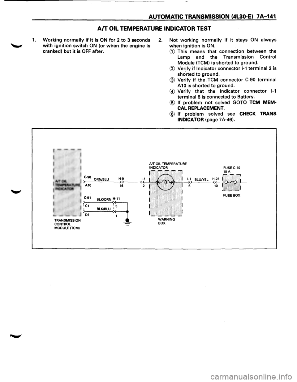
A/T OIL TEMPERATURE INDICATOR TEST
1. Working normally if it is ON for 2 to 3 seconds
with ignition switch ON (or when the engine is
cranked)
but it is OFF after.
2. Not working normally if it stays ON always
when ignition is ON.
CD This means that connection between the
Lamp and the Transmission
Control
Module (TCM) is shorted to ground.
r~,··mm -,-,~
• , I
I
TRANSMISSION
CONTROL
MODULE (TCM)
@ Verify if Indicator connector 1-1 terminal 2 is
shorted
to ground.
@ Verify if the TCM connector C-90 terminal
A10 is shorted to ground.
@ Verify that the Indicator connector 1-1
terminal 6 is connected to Battery.
@ If problem not solved GOTO TCM MEM
CAL REPLACEMENT.
@ If problem solved see CHECK TRANS
INDICATOR
(page 7A-46).
AfT OIL TEMPERATURE INDICATOR ~-~--~I
C-90 ORNJBLU H-9 1~1 :·' ,.· . 'I 1-1 >-A-10--=.:..;.;_;:,=-~>>----<( · , . ' >• • _;__I ;:. 16 2 1 . • .i· ,..:., • 6
I ·•'I• ·. . , . . J
BLU!YEL
BLKJORND
BLK/IILU ~~
I II 1
I I
1_:1;_-:....... _]
WARNING BOX
FUSE BOX
Page 1014 of 1928
7A-142 AUTOMATIC TRANSMISSION (4l30-E)
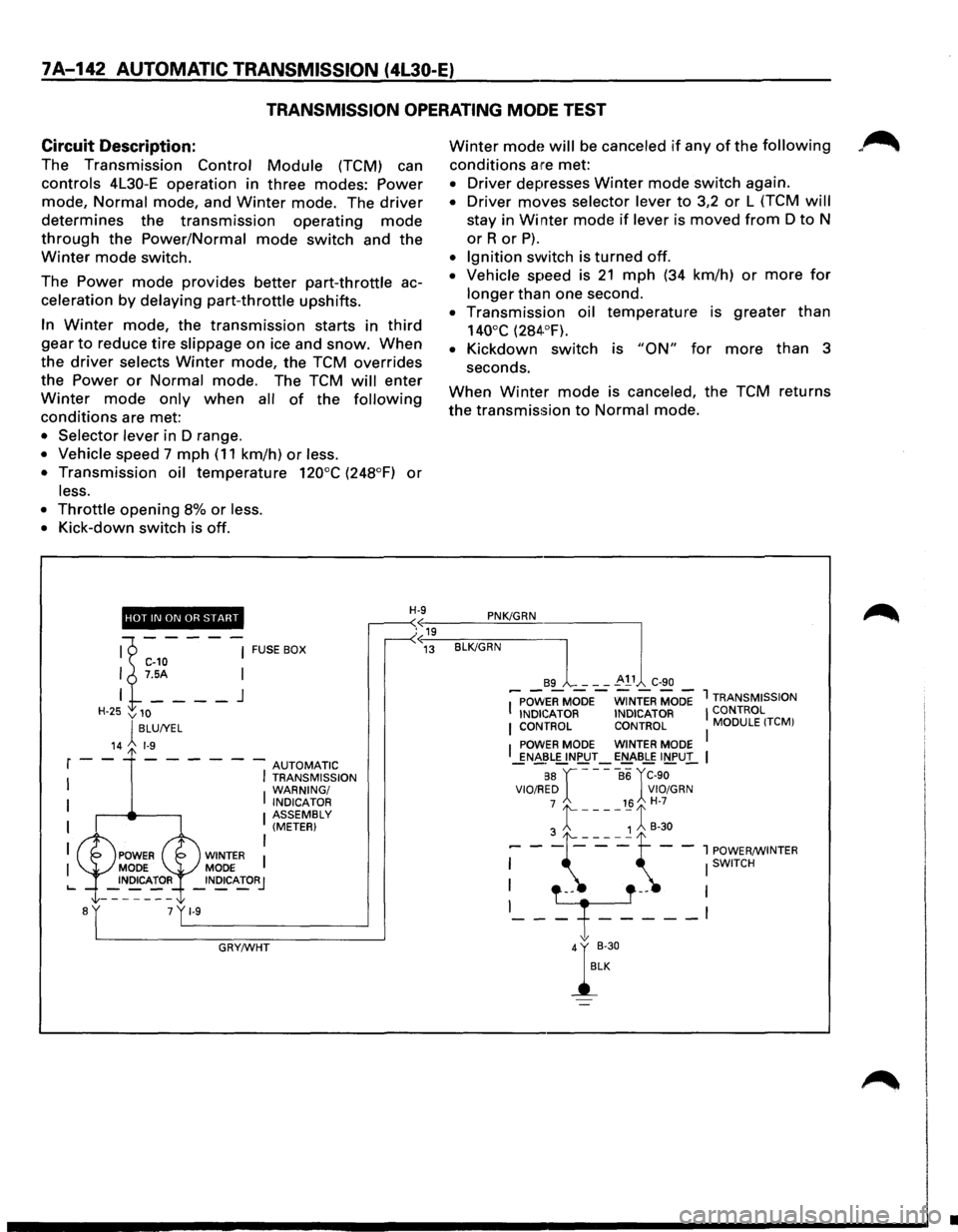
TRANSMISSION OPERATING MODE TEST
Circuit
Description:
The Transmission Control Module (TCM) can
controls 4L30-E operation in three modes: Power
mode, Normal mode, and Winter mode. The driver
determines the transmission operating mode
through the Power/Normal mode switch and the
Winter mode switch.
The
Power mode provides better part-throttle ac
celeration
by delaying part-throttle upshifts.
In Winter mode, the transmission starts in third
gear to reduce tire slippage on ice and snow. When
the driver selects Winter mode, the TCM overrides
the
Power or Normal mode. The TCM will enter
Winter mode only when all of the following
conditions are met:
• Selector lever in D range.
• Vehicle speed 7 mph ( 11 km/h) or less.
•
Transmission oil temperature 120°C (248°F) or
less.
•
Throttle opening 8% or less.
•
Kick-down switch is off.
Winter mode will be canceled if any of the following
conditions are met:
• Driver depresses Winter mode switch again.
• Driver moves selector lever to 3,2 or L (TCM will
stay in Winter mode if lever is moved from D to N
orR or P).
• Ignition switch is turned off.
• Vehicle speed is 21 mph (34 km/h) or more for
longer than one second.
• Transmission oil temperature is greater than
140°C (284·°F).
• Kickdown switch is "ON" for more than 3
seconds.
When Winter mode is canceled, the TCM returns
the transmission
to Normal mode.
HOT IN ON OR START H-9 PNK/GRN
.«19 u
'1----~ FUSEBOX C-10 I 7.5A I
I
____ J
H-25 v 10
lBLUIYEL
14 1-9
r--- - - --AUTOMATIC
I
I I TRANSMISSION
WARNING/
I INDICATOR I ASSEMBLY (METER)
I
I WINTER MODE _INOICATORJ
GRY/WHT
«~13~-BL-K/~G-R-N----]
89 - - -~ 11 C-90
I~POW'ERMOOE-WiNTER MODE 1 TRANSMISSION
INDICATOR INDICATOR I CONTROL I CONTROL CONTROL MODULE !TCMI
I POWER MODE WINTER MODE I _gN~~L[.!NPUT-E!:::J£-BLE INPUl.. I
88 r ----86 rC-90 VIO/RED VIO/GRN 7 16 H-7
3 t ----~ 1 B-30
--\~~~--:~~~~NTER
-T---~
};
•
Page 1024 of 1928
•
, cCi" -.J )> I .... N
RELAY
& FUSE BOX
(FL-1, FL-2, FL-3)
THROTTLE BODYASM SPEED SENSOR
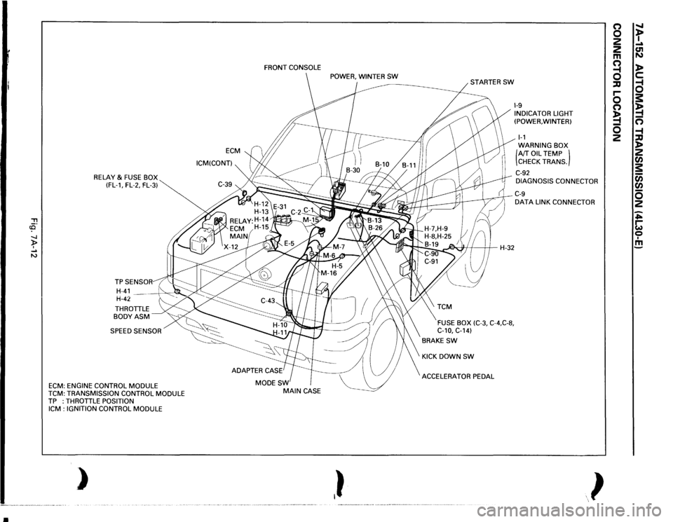
ECM:
ENGINE CONTROL
MODULE
TCM:
TRANSMISSION CONTROL
MODULE
TP :THROTTLE
POSITION
ICM
: IGNITION CONTROL
MODULE
)
ECM
ICM(CONT) FRONT
CONSOLE
MODESW
MAIN
CASE
,}
~H-32
FUSE BOX
(C-3,
C-4,C-8,
C-10,
C-14)
BRAKE
SW
KICK DOWN
SW
ACCELERATOR PEDAL
1-9 INDICATOR LIGHT
(POWER, WINTER) 1-1 WARNING BOX (AfT
OIL
TEMP )
CHECK TRANS.
C-92 DIAGNOSIS CONNECTOR C-9 DATA
LINK CONNECTOR
}
(') 0 2
2 m a ::IJ r-0 (') !4 0 2
" t .... C1l N l> c: a s: !4 n -4 ::IJ l> 2 rA s: c;; rA 0 2 ~ ~ 0 I m
Page 1207 of 1928
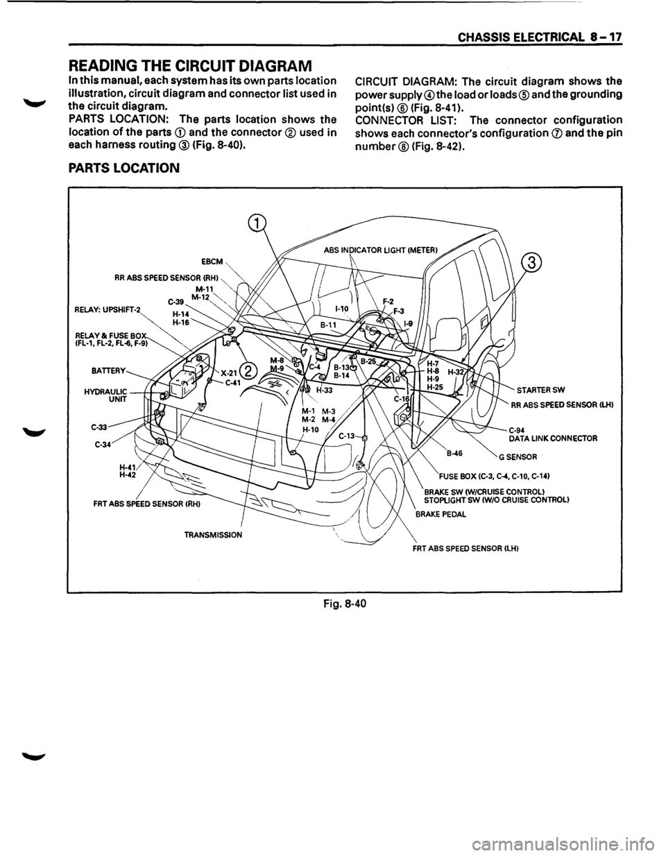
READING THE CIRCUIT DIAGRAM
In this manual, each system has its own parts location
illustration,
circuit diagram and connector list used in
the circuit diagram.
PARTS LOCATION: The parts location shows the
location of the parts CD and the connector® used in
each harness routing ® (fig. 8-40).
PARTS LOCATION
EBCM-,
RR ABS SPEED SENSOR (RHI "',~ M-11 ,,
C-39 M-12~'-, RELAY: UPSHIFT-2 ~
CHASSIS ELECTRICAL 8-17
CIRCUIT DIAGRAM: The circuit diagram shows the
powersupply@the load or loads® and the grounding
point(s)
® (Fig. 8-41 ).
CONNECTOR LIST: The connector configuration
shows
each connector's configuration (J) and the pin
number® (Fig. 8-42).
RELAY & FUSE BO~"'
7
~<-:;;;:~:~:_::0:;;::::'=l-\,.-..:._::::;;,...6
IFL-1, FL-2, FL-6, F-91 , "" ;;~~~~~~~;g~~k~
C-33
C-34
Fig. 8-40
STARTERSW
RR ABS SPEED SENSOR ILHI
C-94 DATA LINK CONNECTOR
GSENSOR
FUSE BOX IC-3, C-4, C-10, C-141
BRAKE SW IW/CRUISE CONTROL! STOPLIGHT SW (W/0 CRUISE CONTROL!
FRT ABS SPEED SENSOR ILHI
Page 1211 of 1928
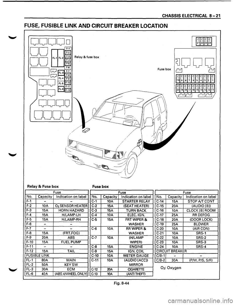
CHASSIS ELECTRICAL 8-21
FUSE, FUSIBLE LINK AND CIRCUIT BREAKER LOCATION
ooooo 112~12~1~1~1
00 E
EEr 00 ~
Relay & fuse box
SJOOO 7-6
I lw ;;::;~ Fuse box ~ ~
1l1~~ ~lff~UIH~Inll
w~ F-a FL-4 ~
00 FL·S~ r---, F-11 'l2~J1~ 1~1&11~11~1,\l~31hl1~1
0
0
FL-6 'F-i2
I' ~
\a~ a~;
0000
0000
I ~
l/
~
j
~/~/ e:;?' v II I / / .I / /
('-/ .
~~
-~-~;,a~ ~~ --.:_
~~~~ -
Relay & Fuse box Fuse box
Fuse
Fuse Fuse
No. Capacity Indication on label No. Capacity Indication on label No. Capacity Indication on label
F-1 --C-1 10A STARTER RELAY
C-14 15A STOP A!f CONT
F-2 10A 02 SENSOR HEATER C-2 15A (SEAT HEATER)
C-15 20A (AUDIO [8))
F-3
15A HORN HAZARD C-3 15A
TURN BACK C-16 10A CLOCK (8] ROOM
F-4
15A H/LAMP-LH C-4 10A ELEC.IGN. C-17 25A RR DEFOG
F-5
15A H/LAMP-RH C-5
15A FRTWIPER & C-18 20A (DOOR LOCK)
F-6 --WASHER C-19
25A BLOWER
F-7
- -C-6 10A RRWIPER & C-20 10A (AIR
CON)
F-8
15A (FRT.FOG) WASHER C-21 10A SRS-1
F-9 20A ABS C-7 10A (H/LAMP C-22 10A SRS-2
F-10
15A FUEL PUMP WIPER) C-23 lOA SRS-3
F-11 -
-C-8 15A ENGINE C-24 10A SRS-4
F-12
15A TAIL C-9 15A IGN. COIL CIRCUIT BREAKER
FUSIBLE
LINK
C-10 10A METER GAUGE
C/8-1 --FL-1 80A MAIN C-11 10A
(AUDIO IACC])
C/8-2 30A (P/W, P/S, S/R)
FL-2 50 A KEYSW MIRROR
FL-3 30A ECM C-12 20A CIGARETTE 02: Oxygen
FL-6 40A (ASS 4/WHEEL ONLY) C-13 10A (ANTI THEFT)
Fig. 8-44
Page 1212 of 1928
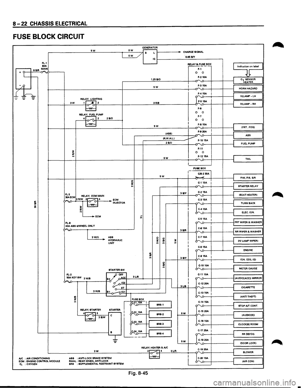
8-22 CHASSIS ELECTRICAL
FUSE BLOCK CIRCUIT
GENERATOR -------------------~s~w~------------~~s~w~--~~~~ r- / B L 1------CHARGE SIGNAL &W _/
FL-1 80A .-----, B 11.'1 MAIN
+ Lt--
l£h
~----/ IG~----------~O~.$~B/V~-----------,
3W REL~HT1NG 1J ---'"~L 3
RELA~PUMP 4 1...---. 12 2 B/0
1.25 B/0
SW
3RJ8
5W
~~~·~ F-1 0 0 F-2 10A
I F-315A
F-8
0 0 F-7 0 0 F-81SA
F-920A
9;nlaool
I
Oz SENSOR HEATER
HORN HAZARD
H/LAMP-LH
H/LAMP-RH
(FRT. FOG)
lABS) -I ABS
I ,--------__:<;;:R·.:.:W.::..Acc·L;;:-1 ____ ----Jv F-10 1SA 2 810
I
~ECM RELAY; ECM MAIN ¢~,...,..J>--+2'-'RIW~_::2~1-o.....-<:>-f-·4.:._ __ _. ~J~CTOR
L...-_.ECM
FL-t 40A ABS 4/WHEEL ONLY
"
.... ...
SW
5W
3 8IY
F-11 0 0 F-1215A
~------' FUSE BOX
CIB-2 30A ~.,.;
C-110A :
C-215A
C-31SA
C-410A
I
J
FUEL PUMP
TAIL
P/W, PIS. SIR
STARTER RELAY
(SEAT HEATER)
TURN BACK
ELEC.IGN.
e-s
15A 1 ""'-.0---t-----+----il FRT WIPER & WASHER
"""' -
I 3W/G
C-810A '---f-+----+.:3.:BIR::::..+---¢""''-£>---i-----f-----jl RR WIPER & WASHER
ABS HYORAULIC UNIT
STARTERSW
FL-2 _JJ OFF
~ ...
..:..AKEYSW 3 W/B ay ' o.N". 3UB
~~--~--~,~------~-0 ~~IG~2Y-----------~ o-: ST 3W/B 81 -.,IG1
FUSE BOX
I
I g1~ 1 J'-:::s:R:s-:1 =I RELAY; STARTER
STARTER I r-
L~---'~-j.t
I I 3UB
sw
C-710A
~';::--~--~-'---~~~HI~LA~M~P~W~IP~E~R~l~~ C-81SA ""'-'>--1---...__---i ENGINE
C-111SA I J~======~l IGN. COIL (G)
C-10 10A
C-1110A
k'-1:>----t----t
~==~I
METER GAUGE
""''-£>---f----------1 (AUDIO[ACC)) MIRROR
C-12 20A
::...1310A I
C-141SA -r"\'-1)----f----t
C-15 20A L,-.
CIGARETTE
(ANTITHEFT)
STOP A/T CONT.
(AUDIO[ B))
C-1810A """"-'-.0---f----------t_j CLOCK[B) ROOM
L---+------------------------iB lt~;_ ~=~~~:~:~::~~~: C-17 2SA I
G1820A
RR DEFOG
= sw (DOOR LOCK) RELAY; HEATER &A/C .:._ __________________ .:.:3~W'-'---------------------~2to~.....-4 3UR C-19 2SA ...... BLOWER
A/C : AIR CONDITIONING ECM : ENGINE CONTIIOL MODULE 0, :OXYGEN ABS
:ANTI-LOCK
BRAKE BYBTEM
RWAL: REAR WHEEL ANTI-LOCK BRB : SUPPLEMENTAL RESTRAINT SYSTEM
C-20 10A (AIR CON)
Fig. 8-45
•