heater ISUZU TROOPER 1995 Workshop Manual
[x] Cancel search | Manufacturer: ISUZU, Model Year: 1995, Model line: TROOPER, Model: ISUZU TROOPER 1995Pages: 1928
Page 14 of 1928
OA-10 GENERAL INFORMATION
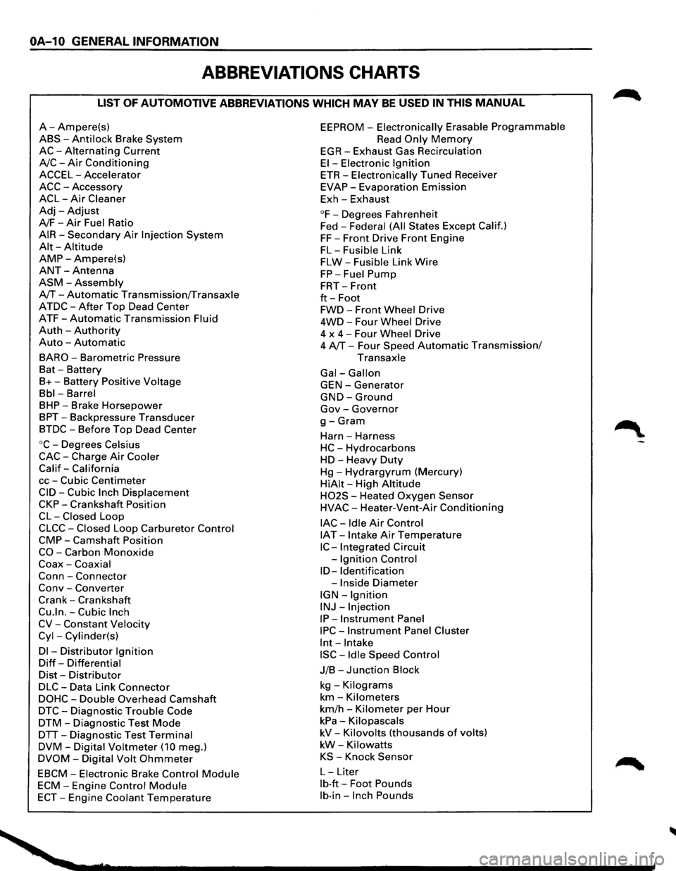
ABBREVIATIONS CHARTS
LIST OF AUTOMOTIVE ABBREVIATIONS WHICH MAY BE USED IN THIS MANUAL
A-Ampere(s)
ABS-Anti lock Brake System
AC-Alternating Current
A/C-Air Conditioning
ACCEL-Accelerator
ACC-Accessory
ACL-Air Cleaner
Adj-Adjust
A/F-Air Fuel Ratio
AIR-Secondary Air Injection System
Alt-Altitude
AMP-Ampere(s)
ANT-Antenna
ASM-Assembly
A/T-Automatic Transmission/Transaxle
ATDC-After Top Dead Center
ATF-Automatic Transmission Fluid
Auth -Authority
Auto -Automatic
BARO-Barometric Pressure
Bat -Battery
B+-Battery Positive Voltage
Bbl-Barrel
BHP-Brake Horsepower
BPT-Backpressure Transducer
BTDC-Before Top Dead Center
oc-Degrees Celsius
CAC-Charge Air Cooler
Calif-California
cc-Cubic Centimeter
CID-Cubic Inch Displacement
CKP-Crankshaft Position
CL-Closed Loop
CLCC-Closed Loop Carburetor Control
CMP-Camshaft Position
CO-Carbon Monoxide
Coax-Coaxial
Conn-Connector
Conv -Converter
Crank-Crankshaft
Cu.ln.-Cubic Inch
CV-Constant Velocity
Cyl-Cylinder(s)
Dl -Distributor Ignition
Diff-Differential
Dist-Distributor
DLC-Data Link Connector
DOHC-Double Overhead Camshaft
DTC-Diagnostic Trouble Code
DTM-Diagnostic Test Mode
DTT-Diagnostic Test Terminal
DVM-Digital Voltmeter (10 meg.)
DVOM-Digital Volt Ohmmeter
EBCM-Electronic Brake Control Module
ECM-Engine Control Module
ECT-Engine Coolant Temperature
EEPROM -Electronically Erasable Programmable
Read Only Memory
EGR-Exhaust Gas Recirculation
El-Electronic Ignition
ETR-Electronically Tuned Receiver
EVAP-Evaporation Emission
Exh-Exhaust
°F-Degrees Fahrenheit
Fed -
Federal (All States Except Calif.)
FF-Front Drive Front Engine
FL-Fusible Link
FLW-Fusible Link Wire
FP-Fuel Pump
FRT-Front
ft-Foot
FWD-Front Wheel Drive
4WD-Four Wheel Drive
4 x
4-Four Wheel Drive
4 A/T-Four Speed Automatic Transmission/
Transaxle
Gal-Gallon
GEN-Generator
GND-Ground
Gov-Governor
g-Gram
Harn -Harness
HC-Hydrocarbons
HD-Heavy Duty
Hg-Hydrargyrum (Mercury)
HiAit-High Altitude
H02S - Heated Oxygen Sensor
HVAC-Heater-Vent-Air Conditioning
lAC-Idle Air Control
IAT -Intake Air Temperature
IC-Integrated Circuit
-
Ignition Control
ID-Identification
-Inside Diameter
IGN-Ignition
INJ-Injection
IP-Instrument Panel
IPC-Instrument Panel Cluster
lnt-Intake
ISC-Idle Speed Control
J/B-Junction Block
kg -Kilograms
km-Kilometers
km/h -Kilometer per Hour
kPa-Kilopascals
kV-Kilovolts (thousands of volts)
kW-Kilowatts
KS -Knock Sensor
L-Liter
lb·ft-Foot Pounds
lb·in-Inch Pounds
Page 19 of 1928
(
(
(
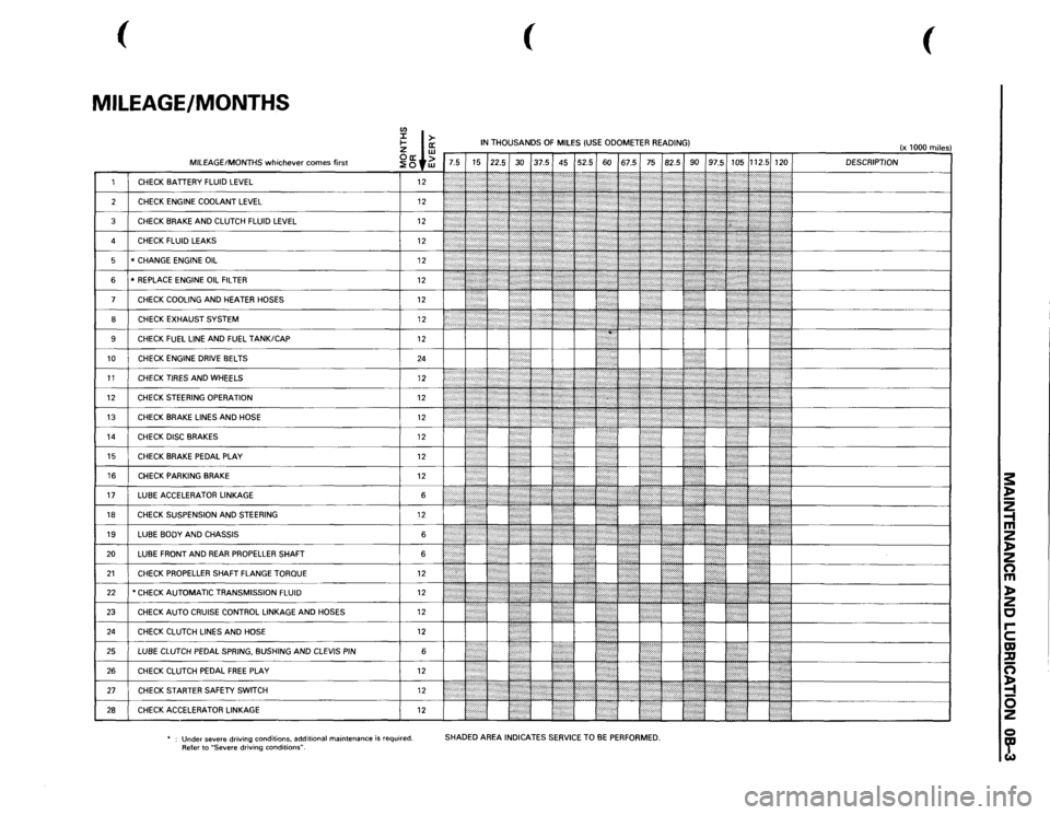
MILEAGE/MONTHS
rn
I ffi
IN THOUSANDS
OF
MILES
(USE
ODOMETER READING)
(x 1000
miles)
~ +~
7.5 15 22.5
30
37.5 45 52.5
60
67.5
75
82.5
90
97.5
105
112.5
120 DESCRIPTION
1
CHECK
BATTERY
FLUID
LEVEL
12
2'-'.:j:
:':
';;;;;
I '' ''
,,,,,,,,,:
[}
2
CHECK
ENGINE
COOLANT
LEVEL
12
':iti:·:
(''''/''?
'';?
,,,,,,,;.;.,.,....
,,,~~
3
CHECK
BRAKE
AND
CLUTCH
FLUID
LEVEL
12
:;:;:;:;:·:·:·.
\::':\' '\"':(\':'''''''''
:'·'·'·:·.,.,,,,
d~~~~~~-------------~
)''
'"''''{''''
'}';;o;o;;
l':':':·:o·.·o·····
4
CHECK
FLUID
LEAKS
12
•.•••..••• ,,......
,,,,,,,,,,,
5
* CHANGE
ENGINE
OIL
12
:.•••:•····
f ) : •
: ; ' {
1:':''''
6
*REPLACE
ENGINE
OIL
FILTER
12
{\::::::::;
[:(o:'.
7
CHECK
COOLING
AND
HEATER
HOSES
12
I : ' :
?
,,,.,,,,,.,:,
.. ;
! • !
•••••••••.
8
CHECK
EXHAUST
SYSTEM
12
I
~
J
:
: ••;·,·····,:·:';';·
•••::::::::::·:;.;
I ;J
., ..... .
9
CHECK
FUEL
LINE
AND
FUEL
TANK/CAP
12
10
CHECK
ENGINE
DRIVE
BELTS
24
. .
I
I
11
CHECKTIRESANDWHEELS
12
li
1:;:~:
}::,
..... ::::, .. ,::,:,:,:,·····
j
12
CHECK
STEERING
OPERATION
12
1
r ., .. ,,.,,.
·
I
13
CHECK
BRAKE
LINES
AND
HOSE
12
~
~
<
.,>
/ ':'??i'
}
J
t
''}{
14
CHECK
DISC
BRAKES
12
10
}}
UL
'I I
•....
15
CHECK
BRAKE
PEDAL
PLAY
12
I"
.. )t
16
CHECK
PARKING
BRAKE
12
li
I
17
LUBE
ACCELERATOR
LINKAGE
6
,,.:
....
I
18
CHECK
SUSPENSION
AND
STEERING
12
••·•••·•··•
19
LUBE
BODY
AND
CHASSIS
6
1''''':'''''''''''
20
LUBE
FRONT
AND
REAR
PROPELLER
SHAFT 6
{:
!: • :•••••l
21
CHECK
PROPELLER
SHAFT FLANGE
TORQUE
12
•
22
*CHECK AUTOMATIC TRANSMISSION
FLUID
12
... ,, ,....
@{I{
,,,,,,,,
ttJ
·~+---------------!
23
CHECK
AUTO
CRUISE
CONTROL
LINKAGE
AND
HOSES
12
~ .
:l
!•••:
24
CHECK
CLUTCH
LINES
AND
HOSE
12
25
LUBE
CLUTCH
PEDAL
SPRING,
BUSHING
AND
CLEVIS
PIN
6
l':":"·:"ii
26
CHECK
CLUTCH
PEDAL
FREE
PLAY
12
1/JJ(
21
cHEcK sTARTER SAFETY swiTCH 12
1/,,,,.,,,,,,,,,
,,,,,,,,,
-~~~--~~~~~~-~~~~~[============J
28
CHECK
ACCELERATOR
LINKAGE
12
m ::::::::]
!•'····
'.!
Under
severe driving conditions,
additional
maintenance
is required.
Refer to
"Severe
driving
conditions".
SHADED AREA
INDICATES
SERVICE
TO
BE PERFORMED.
s: ~ 2 -1 m 2 )> 2 n m )> 2 c rc m ::u n ~ 0 2 Q ~
Page 31 of 1928
HEATING AND VENTILATION 1A-1
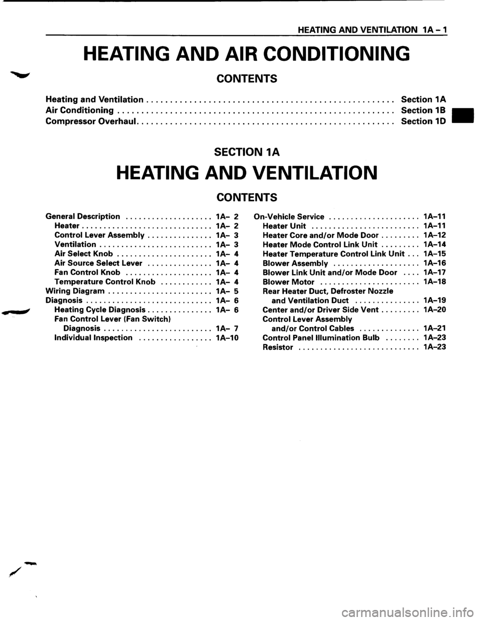
HEATING AND AIR CONDITIONING
CONTENTS
Heating and Ventilation .................................................... Section 1A
Air Conditioning . . . . . . . . . . . . . . . . . . . . . . . . . . . . . . . . . . . . . . . . . . . . . . . . . . . . . . . . . . Section 1 B
Compressor Overhaul. . .
. . . . . . . . . . . . . . . . . . . . . . . . . . . . . . . . . . . . . . . . . . . . . . . . . . . Section 1 D
SECTION 1A
HEATING AND VENTILATION
CONTENTS
General Description .................... 1A-2 On-Vehicle Service ..................... 1A-11
Heater . . . . . . . . . . . . . . . . . . . . . . . . . . . . . . 1
A-2 Heater Unit . . . . . . . . . . . . . . . . . . . . . . . . . 1A-11
Control Lever Assembly . . . . . . . . . . . . . . . 1 A-3 Heater Core and/or Mode Door ......... 1A-12
Ventilation .......................... 1A-3 Heater Mode Control Link Unit ......... 1A-14
Air Select Knob . . . . . . . . . . . . . . . . . . . . . . 1 A-4 Heater Temperature Control Link Unit ... 1A-15
Air Source Select Lever ............... 1A-4 Blower Assembly .................... 1A-16
Fan Control Knob .................... 1A-4 Blower Link Unit and/or Mode Door . . . . 1A-17
Temperature Control Knob ............ 1A-4 Blower Motor ....................... 1A-18
Wiring Diagram . . . . . . . . . . . . . . . . . . . . . . . . 1A-5
Rear Heater Duct, Defroster Nozzle
Diagnosis ............................. 1A-6 and Ventilation Duct ............... 1A-19
.. # Heating Cycle Diagnosis ............... 1A-6 Center and/or Driver Side Vent ......... 1A-20
Fan Control Lever (Fan Switch) Control Lever Assembly
Diagnosis . . . . . . . . . . . . . . . . . . . . . . . . . 1 A-7 and/or Control Cables .............. 1A-21
Individual Inspection ................. 1A-10 Control Panel Illumination Bulb ........ 1A-23
Resistor ............................ 1A-23
Page 32 of 1928
1A-2 HEATING AND VENTILATION
GENERAL DESCRIPTION
HEATER
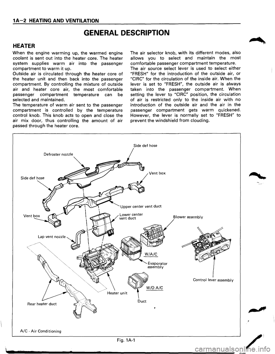
When the engine warming up, the warmed engine
coolant is sent out into the heater core. The heater
system
supplies warm air into the passenger
compartment to warm it up.
Outside air is
circulated through the heater core of
the heater unit and then back into the passenger
compartment. By
controlling the mixture of outside
air and heater core air, the
most comfortable
passenger compartment temperature can be
selected and maintained.
The temperature
of warm air sent to the passenger
compartment is controlled by the temperature
control knob. This knob acts to open and close the
air
mix door, thus controlling the amount of air
passed through the heater core.
Defroster nozzle
Side
def hose
The air selector knob, with its different modes, also
allows
you to select and maintain the most
comfortable passenger compartment temperature.
The air source
select lever is used to select either
"FRESH" for the introduction of the outside air, or
"CIRC" for the circulation of the inside air. When the
lever is set to "FRESH", the outside air is always
taken into the passenger compartment. When
setting the
lever to "CIRC" position, the circulation
of air is restricted only to the inside air with no
introduction
of the outside air and the air in the
passenger
compartment gets warm quickened.
However, the
lever is normally set to "FRESH" to
prevent the windshield from clouding.
Upper center vent duct
A/C-Air Conditioning Lower
center vent duct
<
Heater unit
Duct
Fig. 1A-1
Blower
assembly
Evaporator assembly
Control lever assembly
W/0 A/C
/'
Page 33 of 1928
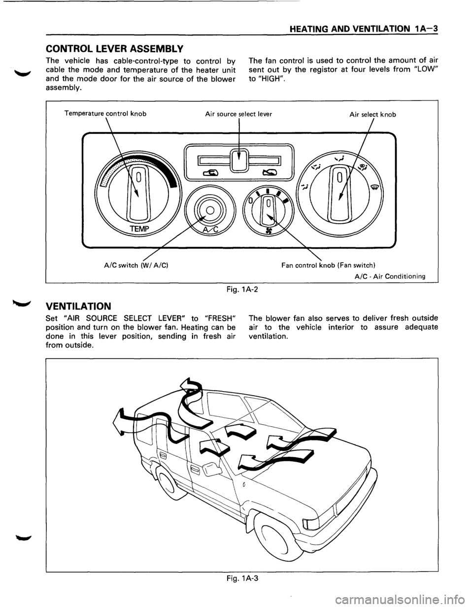
CONTROL LEVER ASSEMBL V
The vehicle has cable-control-type to control by
cable the mode and temperature of the heater unit
and the mode door for the air source of the blower
assembly.
HEATING AND VENTILATION 1A-3
The fan control is used to control the amount of air
sent
out by the registor at four levels from "LOW"
to "HIGH".
Temperature control knob Air source select lever Air select knob
A/C switch (WI A/C) Fan control knob (Fan switch)
A/C-Air Conditioning
Fig. 1A-2
,__,.. VENTILATION
Set "AIR SOURCE SELECT LEVER" to "FRESH"
position and turn on the blower fan. Heating can be
done in this
lever position, sending in fresh air
from outside. The
blower fan also serves
to deliver fresh outside
air
to the vehicle interior to assure adequate
ventilation.
Fig. 1A-3
Page 34 of 1928
1A-4 HEATING AND VENTILATION
AIR SELECT KNOB
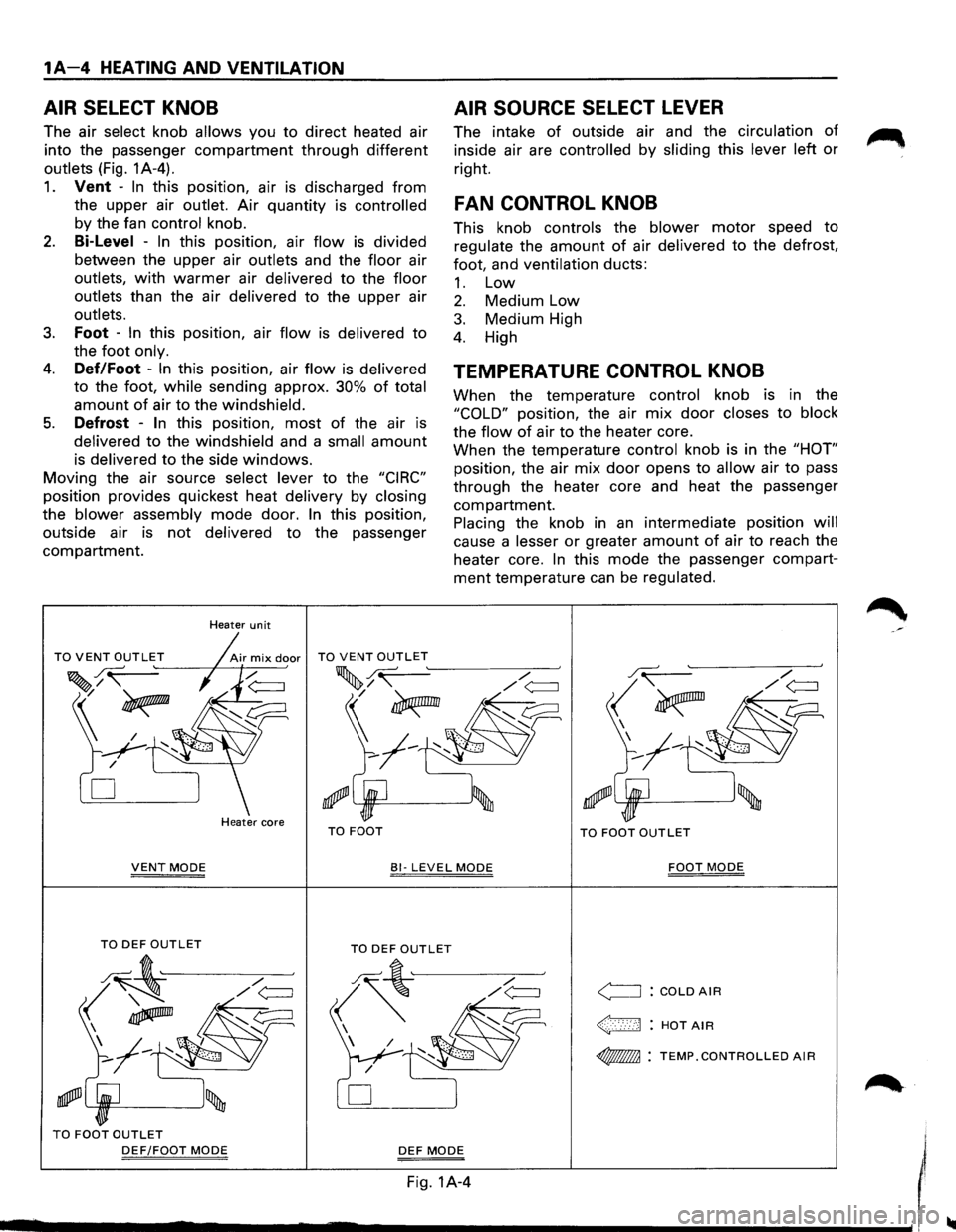
The air select knob allows you to direct heated air
into the passenger
compartment through different
outlets (Fig. 1A-4).
1. Vent -In this position, air is discharged from
the upper air
outlet. Air quantity is controlled
by the fan control knob.
2. Bi-Level -In this position, air flow is divided
between the upper air
outlets and the floor air
outlets, with warmer air delivered to the floor
outlets
than the air delivered to the upper air
outlets.
3. Foot -In this position, air flow is delivered to
the foot only.
4. Def/Foot -In this position, air flow is delivered
to the foot, while sending approx. 30% of total
amount of air to the windshield.
5. Defrost -In this position, most of the air is
delivered to the windshield and a small amount
is delivered to the side windows.
Moving the air source select lever to the "CIRC"
position provides quickest heat delivery by closing
the blower assembly mode door. In this position,
outside air
is not delivered to the passenger
compartment.
Heater unit
D
Heater core TO FOOT
AIR SOURCE SELECT LEVER
The intake of outside air and the circulation of
inside air are controlled by sliding this lever left or
right.
FAN CONTROL KNOB
This knob controls the blower motor speed to
regulate the amount of air delivered to the defrost,
foot, and
ventilation ducts:
1. Low
2. Medium Low
3. Medium High
4. High
TEMPERATURE CONTROL KNOB
When the temperature control knob is in the
"COLD" position, the air mix door closes to block
the flow of air to the heater core.
When the temperature
control knob is in the "HOT"
position, the air mix door opens to allow air to pass
through the heater core and heat the passenger
compartment.
Placing the knob in an intermediate position will
cause a lesser or greater amount of air to reach the
heater core.
In this mode the passenger compart
ment temperature can be regulated.
.r.( /
<_;~~
'--'R!I=---_____.J'
TO FOOT OUTLET
VENT MODE 81-LEVEL MODE FOOT MODE
TO FOOT OUTLET
DEF/FOOT MODE DEF MODE
Fig. 1A-4
<==:J : COLD AIR
~: HOTAIR
~ : TEMP.CONTROLLED AIR
I ........................................................................\
...... ------------------~1
Page 36 of 1928
1A-6 HEATING AND VENTILATION
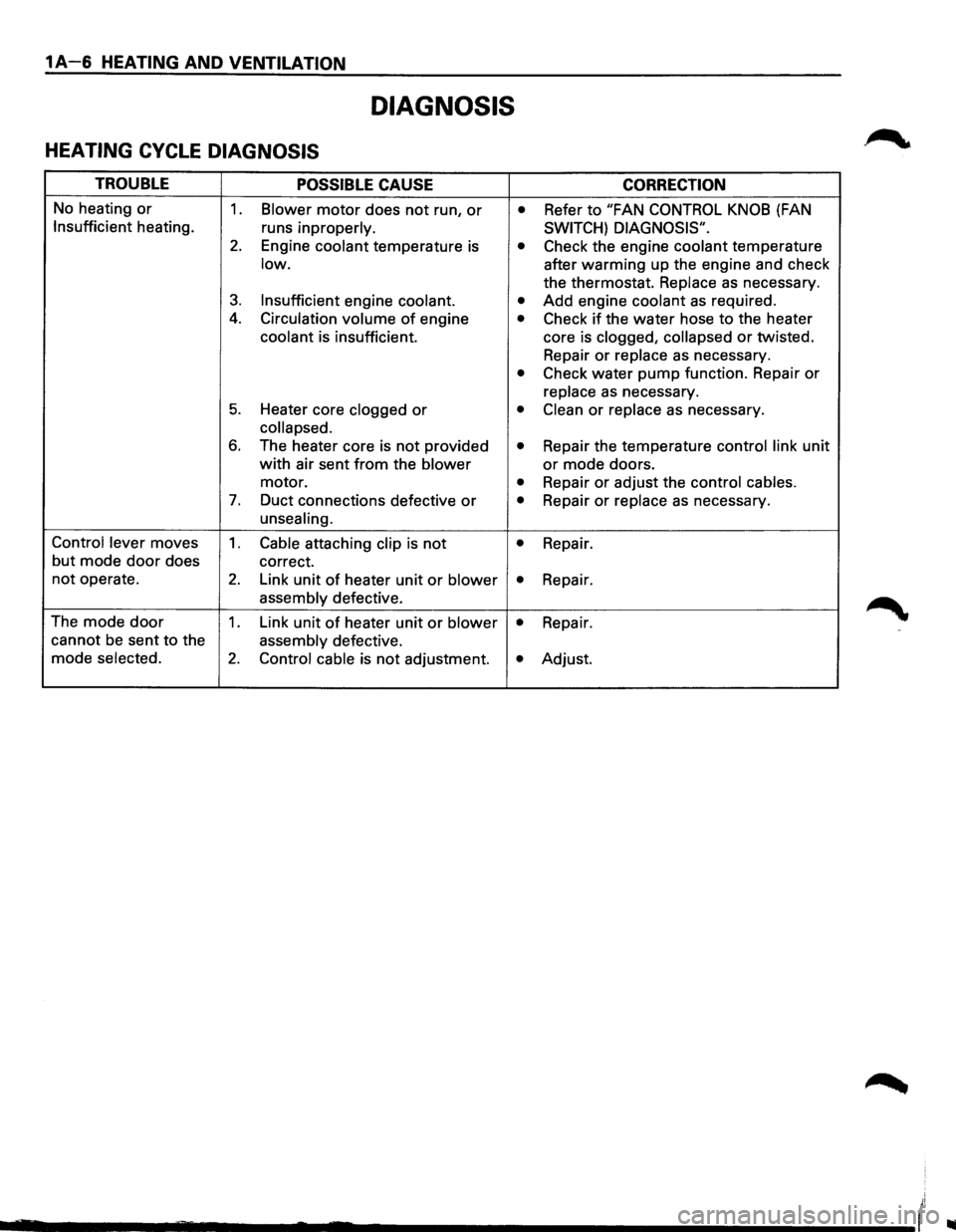
DIAGNOSIS
HEATING CYCLE DIAGNOSIS
TROUBLE POSSIBLE CAUSE CORRECTION
No heating or 1. Blower motor does not run, or • Refer to "FAN CONTROL KNOB (FAN
Insufficient heating.
runs inproperly. SWITCH) DIAGNOSIS".
2. Engine coolant temperature is • Check the engine coolant temperature
low. after warming up the engine and check
the thermostat.
Replace as necessary.
3. Insufficient engine coolant. • Add engine coolant as required .
4. Circulation volume of engine • Check if the water hose to the heater
coolant is insufficient. core is clogged, collapsed or twisted.
Repair
or replace as necessary.
• Check water pump function. Repair or
replace as necessary.
5. Heater core clogged or • Clean or replace as necessary.
collapsed.
6. The heater core is not provided • Repair the temperature control link unit
with air sent from the blower or mode doors.
motor.
• Repair or adjust the control cables.
7. Duct connections defective or • Repair or replace as necessary.
unsealing.
Control lever
moves 1. Cable attaching clip is not • Repair.
but
mode door does correct.
not operate. 2. Link unit of heater unit or blower • Repair.
assembly defective.
The
mode door 1. Link unit of heater unit or blower • Repair.
cannot
be sent to the assembly defective.
mode
selected. 2. Control cable is not adjustment. • Adjust.
_______ __... ..... ..._ ____________ (
Page 37 of 1928
FAN CONTROL LEVER (FAN SWITCH)
DIAGNOSIS
HEATING AND VENTILATION 1A-7
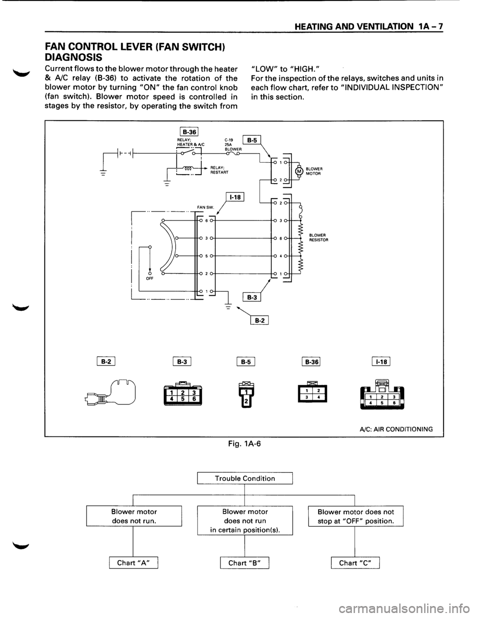
Current flows to the blower motor through the heater
& A!C relay (8-36) to activate the rotation of the
blower motor by turning "ON" the fan control knob
(fan switch).
Blower motor speed is controlled in
stages
by the resistor, by operating the switch from
"LOW" to "HIGH."
I B-361 RELAY;
ji!!J
For the inspection of the relays, switches and units in
each
flow chart, refer to "INDIVIDUAL INSPECTION"
in this section.
1
)
BLOWER MOTOR 2
r-··-··-··
FANSW. I
I
I
I
0 OFF
L= _______ _
~ ~
olJ m 6
I
Blower motor
I does not run.
I Chart "A" I
~
iif1
Fig. 1A-6
Trouble Condition
I
l
Blower motor
does not run
in certain position(s).
I
I Chart "B" I I
BLOWER RESISTOR
I B-361
Eili3 4
IT!!]
rl! 6
AJC: AIR
CONDITIONING
I
Blower motor does not
J stop at "OFF" position.
I Chart "C" I
Page 40 of 1928
1A-10 HEATING AND VENTILATION
~ INDIVIDUAL INSPECTION
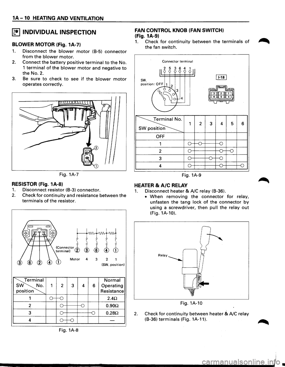
BLOWER MOTOR (Fig. 1A-7)
1. Disconnect the blower motor (B-5) connector
from the blower motor.
2. Connect the battery positive terminal to the No.
1 terminal of the blower motor and negative to
the No.2.
3. Be sure to check to see if the blower motor
operates correctly.
Fig. 1A-7
RESISTOR (Fig. 1A-8)
1. Disconnect resistor (B-3) connector.
2. Check for continuity and resistance between the
terminals of the resistor.
Motor 4 3 2
(SW. position)
Terminal Normal
SW No.
2 3 4 6 Operating
position Resistance
1 2.4Q
2 0.90Q
3 0.28Q
4
Fig. 1A-8
FAN CONTROL KNOB (FAN SWITCH)
(Fig. 1A-9)
1. Check for continuity between the terminals of
the fan switch.
Connector terminal
2 3 4 5 6
OFF
1
2
3
4
Fig. 1A-9
HEATER & A/C RELAY
1. Disconnect heater & A!C relay (B-36).
• When removing the connector for relay,
unfasten the tang lock of the connector by
using a screwdriver, then pull the relay out
(Fig. 1A-10).
Fig. 1A-10
2. Check for continuity between heater & A!C relay
(B-36) terminals (Fig. 1A-11).
~
•
Page 41 of 1928
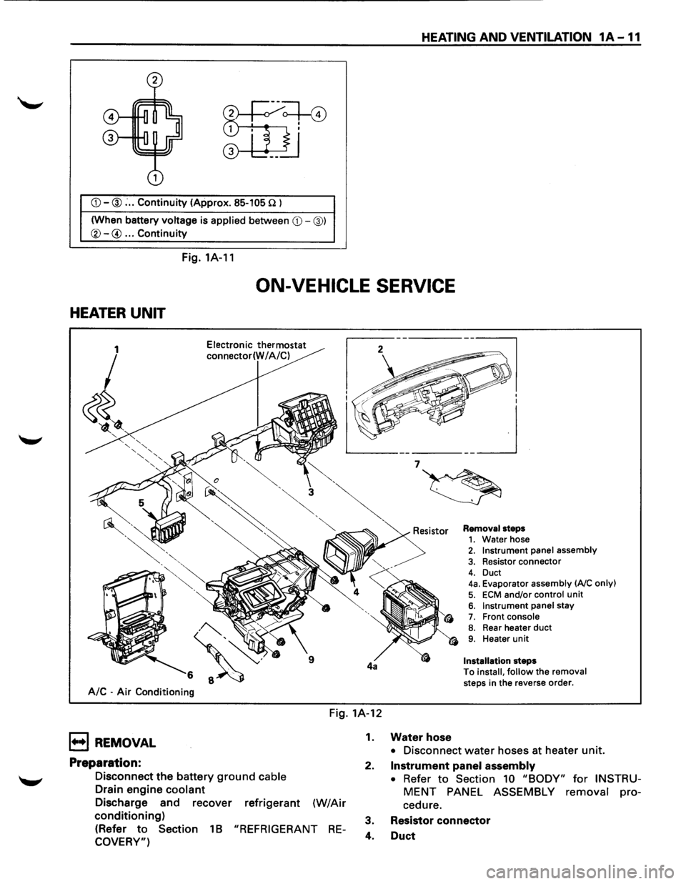
CD-@: .. Continuity (Approx. 85-105 n l
(When battery
voltage is applied between CD-@)
®-@ ... Continuity
Fig. 1A-11
HEATING AND VENTILATION 1A -11
ON-VEHICLE SERVICE
HEATER UNIT
A/C -Air Conditioning
Electronic thermostat
connector(W I A/C)
Removal steps 1. Water hose 2. Instrument panel assembly
3. Resistor connector
4. Duct 4a. Evaporator assembly (AJC only)
5. ECM and/or control unit 6. Instrument panel stay 7. Front console 8. Rear heater duct 9. Heater unit
Installation steps
To
install, follow the removal
steps in the reverse order.
Fig. 1A-12
1••1 REMOVAL
Preparation:
Disconnect the battery ground cable
Drain engine coolant
Discharge and recover refrigerant (W/Air
conditioning)
(Refer to Section 1 B "REFRIGERANT RE
COVERY")
1. Water hose
• Disconnect water hoses at heater unit.
2.
Instrument panel assembly
• Refer to Section 10 "BODY" for INSTRU
MENT PANEL ASSEMBLY removal pro
cedure.
3. Resistor
connector
4. Duct