ESP ISUZU TROOPER 1995 Workshop Manual
[x] Cancel search | Manufacturer: ISUZU, Model Year: 1995, Model line: TROOPER, Model: ISUZU TROOPER 1995Pages: 1928
Page 125 of 1928
DIAGNOSIS 3-5
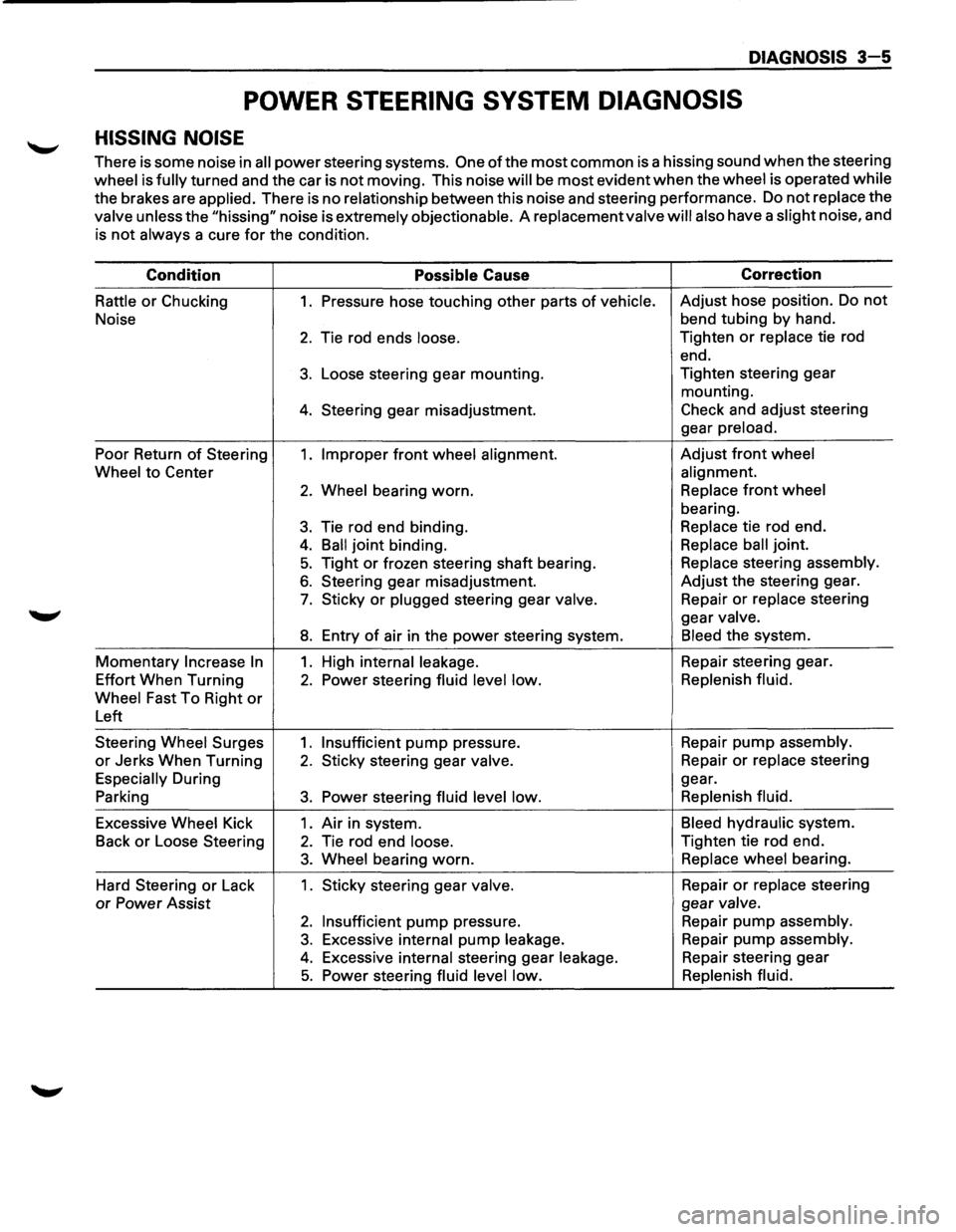
POWER STEERING SYSTEM DIAGNOSIS
HISSING NOISE
There is some noise in all power steering systems. One of the most common is a hissing sound when the steering
wheel is fully turned and the car is not moving. This noise will be most evident when the wheel is operated while
the brakes are applied. There is no relationship between this noise and steering performance. Do not replace the
valve unless the "hissing" noise is extremely objectionable. A replacement valve will also have a slight noise, and
is
not always a cure for the condition.
Condition
Possible Cause Correction
Rattle or Chucking 1. Pressure
hose touching other parts of vehicle. Adjust hose position. Do not
Noise bend
tubing by hand.
2. Tie rod ends loose. Tighten or replace tie rod
end.
3. Loose steering gear mounting. Tighten
steering gear
mounting.
4. Steering gear misadjustment. Check and adjust steering
gear
preload.
Poor Return of Steering 1. Improper front wheel alignment. Adjust front wheel
Wheel
to Center alignment.
2. Wheel bearing worn. Replace front wheel
bearing.
3. Tie rod end binding. Replace tie rod end.
4. Ball joint binding. Replace ball joint.
5. Tight or frozen steering shaft bearing. Replace steering assembly.
6. Steering gear misadjustment. Adjust the steering gear.
7. Sticky or plugged steering gear valve. Repair or replace steering
gear
valve.
8. Entry of air in the power steering system. Bleed the system.
Momentary Increase In 1. High internal leakage. Repair steering gear.
Effort When Turning
2. Power steering fluid level low. Replenish
fluid.
Wheel
Fast To Right or
Left
Steering
Wheel Surges 1. Insufficient pump pressure. Repair pump assembly.
or Jerks
When Turning 2. Sticky steering gear valve. Repair or replace steering
Especially During gear.
Parking
3. Power steering fluid level low. Replenish
fluid.
Excessive Wheel Kick 1. Air in system. Bleed hydraulic system.
Back
or Loose Steering 2. Tie rod end loose. Tighten tie rod end.
3. Wheel bearing worn. Replace wheel bearing.
Hard Steering
or Lack 1. Sticky steering gear valve. Repair or replace steering
or Power Assist gear valve.
2. Insufficient pump pressure.
Repair pump assembly.
3. Excessive internal pump leakage. Repair
pump assembly.
4. Excessive internal steering gear leakage. Repair steering gear
5. Power steering fluid level low. Replenish
fluid.
Page 129 of 1928
DIAGNOSIS 3-9
TIRE DIAGNOSIS
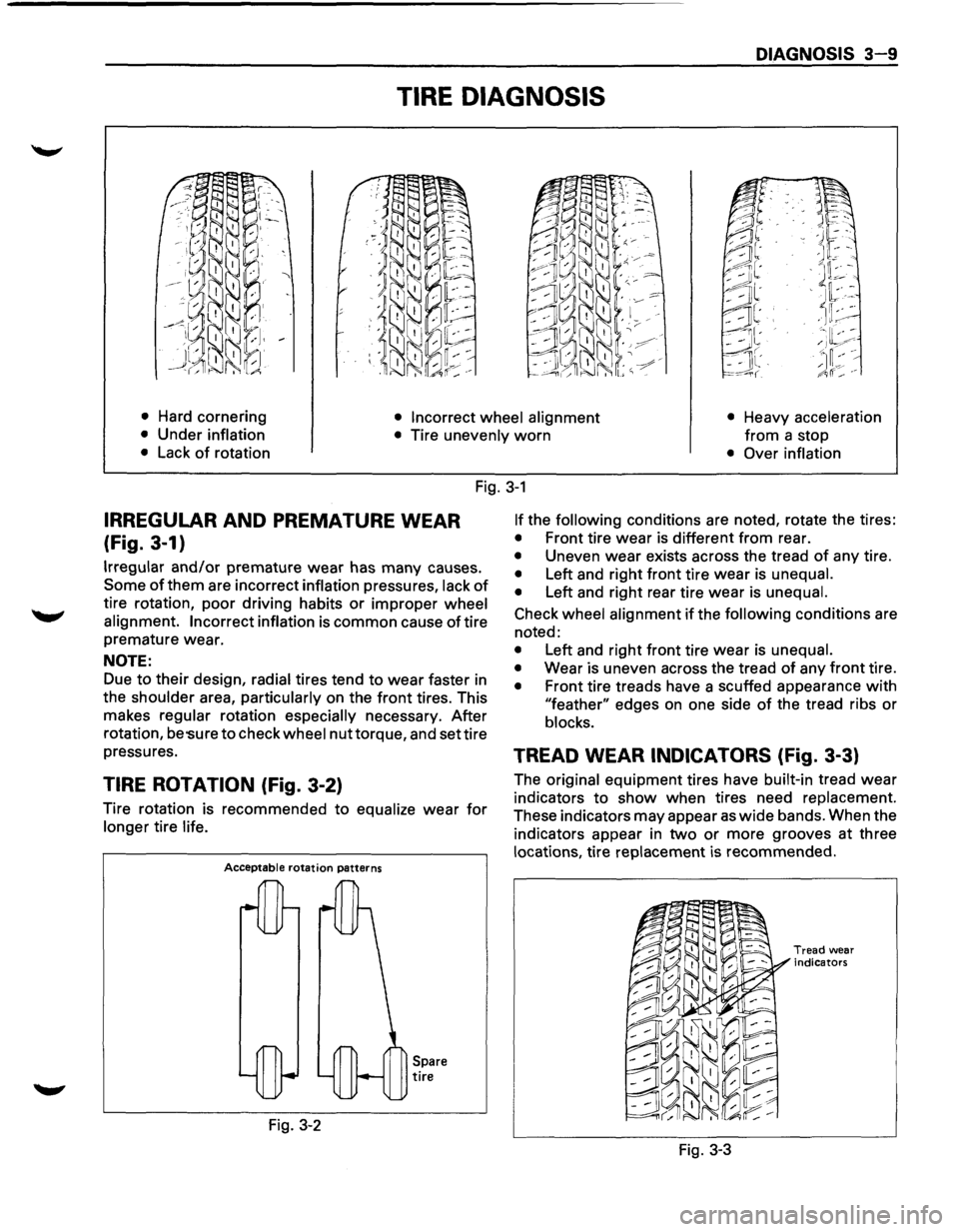
• Hard cornering • Incorrect wheel alignment • Heavy acceleration
from a
stop • Under inflation
• Tire unevenly worn
• Lack of rotation • Over inflation
Fig. 3-1
IRREGULAR AND PREMATURE WEAR
(Fig. 3-1)
Irregular and/or premature wear has many causes.
Some of them are incorrect inflation pressures, lack of
tire rotation, poor driving habits or improper wheel
alignment. Incorrect inflation
is common cause of tire
premature wear.
NOTE:
Due to their design, radial tires tend to wear faster in
the
shoulder area, particularly on the front tires. This
makes
regular rotation especially necessary. After
rotation,
be 'Sure to check wheel nut torque, and set tire
pressures.
TIRE ROTATION (Fig. 3-2)
Tire rotation is recommended to equalize wear for
longer tire life.
Acceptable rotation patterns
Fig. 3-2
Spare tire
If the following conditions are noted, rotate the tires:
• Front tire wear is different from rear.
• Uneven wear exists across the tread of any tire.
• Left and right front tire wear is unequal.
•
Left and right rear tire wear is unequal.
Check wheel alignment if the following conditions are
noted:
• Left and right front tire wear is unequal.
•
Wear is uneven across the tread of any front tire.
• Front tire treads have a scuffed appearance with
"feather" edges on one side of the tread ribs or
blocks.
TREAD WEAR INDICATORS (Fig. 3-3)
The original equipment tires have built-in tread wear
indicators to show when tires need replacement.
These indicators may appear as wide bands. When the
indicators appear in
two or more grooves at three
locations, tire replacement is recommended.
Fig. 3-3
Tread wear
indicators
Page 170 of 1928
![ISUZU TROOPER 1995 Workshop Manual 3C-6 FRONT SUSPENSION
(L!] INSPECTION AND REPAIR
Make necessary correction or parts replacement if
wear, damage, corrosion or any other abnormal
condition are found through inspection.
Ch](/img/61/57183/w960_57183-169.png "ISUZU TROOPER 1995 Workshop Manual 3C-6 FRONT SUSPENSION
(L!] INSPECTION AND REPAIR
Make necessary correction or parts replacement if
wear, damage, corrosion or any other abnormal
condition are found through inspection.
Ch")
3C-6 FRONT SUSPENSION
(L!] INSPECTION AND REPAIR
Make necessary correction or parts replacement if
wear, damage, corrosion or any other abnormal
condition are found through inspection.
Check the following parts:
• Torsion bar
• Height control arm
• Adjust bolt
• Rubber seat
1•+1 INSTALLATION
3. Torsion bar
8 • Make sure the bars are on their correct
respective sides (Fig.
3C-8).
1-ool • Apply grease to the serrated portions.
• Align the setting marks (Fig. 3C-9).
Fig. 3C-8
Fig. 3C-9
2. Height control arm
§]•
u:
Apply grease to the portion that fits into the
bracket.
Align the setting marks (Fig. 3C-1 0).
Apply grease to the bolt portion of the end
piece.
r::=;] • Apply grease to the portion of the seat that fits
D into the bracket (Fig. 3C-11 ).
1-ool • Apply grease to the serrated portions.
Fig.
3C-10
Fig. 3C-11
1. Adjust bolt and seat (Fig. 3C-12)
• Turn the adjust bolt to the setting mark applied
during disassembly.
NOTE:
Adjust the trim height. Refer to "Front End Alignment"
in section 3A.
Setting mark
Fig. 3C-12
IIIII
Page 202 of 1928
3E-2 WHEELS AND TIRES
DIAGNOSIS
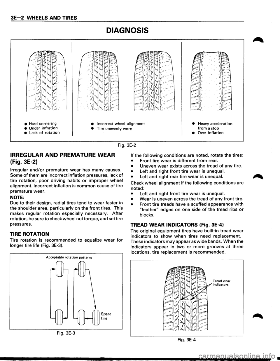
• Hard cornering • Incorrect wheel alignment
• Heavy acceleration from a stop • Under infration • Tire unevenly worn • Lack of rotation • Over inflation
Fig. 3E-2
IRREGULAR AND PREMATURE WEAR
(Fig. 3E-2)
Irregular and/or premature wear has many causes.
Some of them are incorrect inflation pressures, lack of
tire rotation, poor driving habits or improper wheel
alignment. Incorrect inflation
is common cause of tire
premature wear.
NOTE:
Due to their design, radial tires tend to wear faster in
the
shoulder area, particularly on the front tires. This
makes
regular rotation especially necessary. After
rotation, be sure to check wheel nut torque, and set tire
pressures.
TIRE ROTATION
Tire rotation is recommended to equalize wear for
longer tire life (Fig. 3E-3).
Acceptable rotation patterns
Fig. 3E-3
Spare tire
If the following conditions are noted, rotate the tires:
• Front tire wear is different from rear.
• Uneven wear exists across the tread of any tire.
• Left and right front tire wear is unequal.
•
Left and right rear tire wear is unequal.
Check wheel alignment if the following conditions are
noted:
• Left and right front tire wear is unequal.
•
Wear is uneven across the tread of any front tire.
• Front tire treads have a scuffed appearance with
"feather" edges on one side of the tread ribs or
blocks.
TREAD WEAR INDICATORS (fig. 3E-4)
The original equipment tires have built-in tread wear
indicators to show when tires need replacement.
These indicators may appear as wide bands. When the
indicators appear in
two or more grooves at three
locations, tire replacement is recommended.
Fig. 3E-4
Tread wear
indicators
•
Page 207 of 1928
WHEELS AND TIRES 3E-1
TIRES
REPLACEMENT
UNIT REPAIR
WHEELS
REPLACEMENT
When replacement is necessary, the original metric
the size should be used. Most metric tire sizes do not
have exact corresponding alphanumeric tire sizes. It
is recommended that new tires be installed in pairs on
the same axle. If necessary to replace only one tire, it
should be paired with tire having the most tread, to
equalize braking traction.
w CAUTION:
Do not mix different types of tires such as radial,
bias and bias-belted tires except in emergencies,
because
vehicle handling may be seriously
affected and may result in loss of control.
TIRE DISMOUNTING
Remove valve cap on valve step and deflate the tire.
Then use a
tire changing machine to mount or
dismount tires.
Follow the equipment manufacturer's instruction. Do
not use hand tools or tire lever alone to change tires
as they may damage the tire beads or wheel rim.
TIRE MOUNTING
Rim bead seats should be cleaned with a wire brush
....._., or coarse steel wool to remove lubricants, and light
rust. Before mounting a tire, the bead area should be
well lubricated with an approved tire lubricant.
After mounting, inflate the tire to 196kPa (28 psi) so
that beads are completely seated. Inflate the air to
specified pressure and install valve cap to the stem.
\f WARNING:
Never stand over tire when inflating. Bead may
break when bead snaps over rim's safety hump
and cause serious personal injury.
Never exceed
240 kPa (35 psi) pressure when
inflating. If 240 kPa (35 psi) pressure will not
seat beads, deflate, re-lubricate and re-inflate.
Over
inflation may cause the bead to break and
cause serious
personal injury.
TIRE REPAIR
There are many different materials on the market
used to repair tires.
Manufacturers have published detailed instructions
on how and when to repair tires. These instructions
can be obtained from the tire manufacturer if they are
not included with the repair kit. Damaged
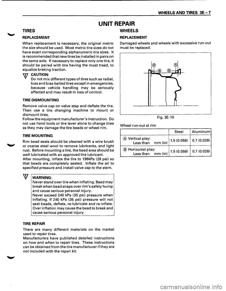
wheels and wheels with excessive run-out
must be replaced.
Fig. 3E-10
Wheel
run-out at rim
Steel Aluminum
@ Vertical play: 1.5 (0.059) 0.7
(0.028) Less than mm(in)
@ Horizontal play: 1.5 (0.059) 0.7
(0.028) Less than mm(in)
Page 273 of 1928
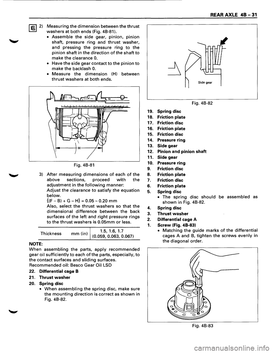
~2) Measuring the dimension between the thrust
washers at both ends (Fig. 48-81 ).
• Assemble the side gear, pinion, pinion
shaft, pressure ring and thrust washer,
and pressing
the pressure ring to the
pinion shaft in the direction of the shaft to
make the clearance 0.
• Have the side gear contact to the pinion to
make the backlash 0.
• Measure the dimension (H) between
thrust washers at both ends.
Fig. 48-81
3) After measuring dimensions of each of the
above sections, proceed with the
adjustment in the following manner:
Adjust the clearance to satisfy the equation
below.
{(F-8) + G-H} = 0.05-0.20 mm
Also, select the thrust washers so that the
dimensional difference between the back
surfaces
of the left and right pressure rings
to the thrust washers is 0.05mm or less.
Thickness (. )
1.5, 1.6, 1.7 mm In (0.059, 0.063, 0.067)
NOTE:
When assembling the parts, apply recommended
gear oil sufficiently to each of the parts, especially, to
the contact surfaces and sliding surfaces.
Recommended oil: 8esco Gear Oil LSD
22. Differential cage B
21. Thrust washer
20. Spring disc
• When assembling the spring disc, make sure
the mounting direction is correct as shown in
Fig. 48-82.
REAR AXLE 48-31
Fig. 48-82
19.
Spring disc
18. Friction plate
17. Friction disc
16. Friction plate
15. Friction disc
14. Pressure ring
13.
Side gear
12. Pinion and pinion shaft
11.
Side gear
10. Pressure ring
9. Friction disc
8. Friction plate
7. Friction disc
6. Friction plate
5. Spring disc
• The spring disc should be assembled as
shown in Fig. 48-82.
4. Spring disc
3. Thrust washer
2. Differential cage A
1. Screw (Fig. 48-83)
• Matching the guide marks of the differential
cages A and 8, tighten the screws evenly in
the diagonal order.
Fig. 48-83
Page 311 of 1928
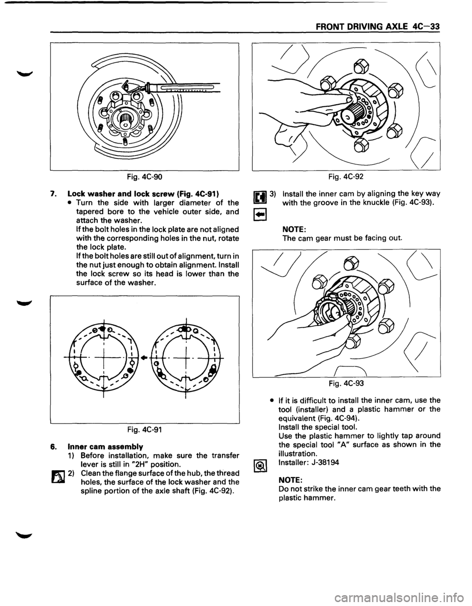
7.
Fig. 4C-90
Lock washer and lock screw (Fig. 4C-91}
• Turn the side with larger diameter of the
tapered bore
to the vehicle outer side, and
attach the washer.
If the bolt holes in the lock plate are not aligned
with the corresponding holes in the nut, rotate
the
lock plate.
If
the bolt holes are still out of alignment, turn in
the
nut just enough to obtain alignment. Install
the lock screw so its head is lower than the
surface
of the washer .
•
Fig. 4C-91
6. Inner cam assembly
1) Before installation, make sure the transfer
lever is still in "2H" position.
1!1::1 2) Clean the flange surface of the hub, the thread
Lil holes, the surface of the lock washer and the
spline portion of the axle shaft (Fig. 4C-92).
FRONT DRIVING AXLE 4C-33
Fig. 4C-92
Install the inner cam by aligning the key way
with the groove in the knuckle (Fig. 4C-93).
NOTE:
The cam gear must be facing out.
Fig. 4C-93
• If it is difficult to install the inner cam, use the
tool (installer) and a plastic hammer or the
equivalent (Fig. 4C-94).
Install the special tool.
Use the plastic hammer to lightly tap around
the
special tool "A" surface as shown in the
illustration.
Installer:
J-38194
NOTE:
Do not strike the inner cam gear teeth with the
plastic hammer.
Page 416 of 1928
5A4-6 4-WHEEL ANTILOCK BRAKE SYSTEM (ABS)
If only rear wheels are rotated using jacks or
drum tester, the system will diagnose a speed
sensor
malfunction and the "ABS" warning
light will illuminate. But actually no trouble
exists. After inspection stop the engine once
and re-start it,
then make sure that the "ABS"
warning light does not illuminate.
If the battery has been discharged
The engine may stall if the battery has been
completely discharged and the engine is started via
a
jumper cable. This is because the Antilock Brake
System (ABS) requires a
large quantity of
electricity. In this case, wait until the battery is
recharged,
or set the ABS to a non-operative state
by removing the fuse for the ABS (40A). After the
battery has been recharged, stop the engine and
install the ABS fuse. Start the engine again, and
confirm that the ABS warning light does not light.
NOTE ON INTERMITTENTS
As with virtually any electronic system, it is difficult
to identify an intermittent failure. In such a case
duplicating the system malfunction during a test
drive
or a good description of vehicle behavior from
the customer may be helpful in locating a "most
likely" failed component or circuit. The symptom
diagnosis chart may also be useful in isolating the
failure. Most intermittent problems are caused by
faulty electrical connections or wiring. When an
intermittent failure is encountered, check suspect
circuits for:
Suspected harness damage.
• Poor mating of connector halves or terminals
not fully seated in the connector body (backed
out).
Improperly formed or damaged terminals.
TEST DRIVING ABS COMPLAINT
VEHICLES
In case that there has been an abnormality in the
lighting pattern of "ABS" warning light, the fault
can be located in accordance with the "DIAGNOSIS
BY 'ABS' WARNING LIGHT ILLUMINATION
PATTERN". In case of such trouble as can be
detected
by the driver as a vehicle symptom,
however, it is necessary to give a test drive
following the test procedure mentioned below,
thereby reproducing the symptom for trouble
diagnosis on a symptom basis:
1. Start the engine and make sure that the "ABS"
W/L goes OFF. If the W/L remains ON, it
means that the Diagnostic Trouble Code (DTC)
is stored. Therefore, read the code and
locate
the fault.
2. Start the vehicle and accelerate to 30 km/h (19
mph) or more.
3. Slowly brake and stop the vehicle completely.
4. Then restart the vehicle and accelerate to 40
km/h (25 mph) or more.
5. Brake at a time so as to actuate the ABS and ... ~
stop the vehicle.
6. Be cautious of abnormality during the test. If
theW/Lis actuated while driving, read the DTC
and locate the fault.
7. If the abnormality is not reproduced by the
test, make best efforts
to reproduce the
situation reported
by the customer.
8. If the abnormality has been detected, repair in
accordance
with the "SYMPTOM DIAGNOSIS".
NOTE:
Be sure to give a test drive on a wide, even
road
with a small traffic.
If an abnormality is detected, be sure to
suspend the test and start
trouble diagnosis at
once.
II ABS" WARNING LIGHT
When ABS trouble occurs to actuate "ABS"
warning light, the trouble code corresponding to
the trouble is stored in the EBCM. Only ordinary
brake is available with ABS being unactuated. Even
when "ABS" warning light is actuated, if the starter
switch is set
ON after setting it OFF once, the EBCM
checks
up on the entire system and, if there is no
abnormality, judges ABS to work currently and the
warning light is lit normally even though the
trouble code is stored.
NOTE:
Illumination of the "ABS" warning light
indicates that antilock braking is no longer
available. Power assisted braking without
antilock control is still available.
NORMAL OPERATION
II ABS" WARNING LIGHT
When the ignition is first moved from "OFF" to
"RUN", the amber "ABS" warning light will turn
"ON". The "ABS" warning light will turn "ON"
during engine starting and will usually stay "ON"
for approximately three seconds after the ignition
switch is returned to the "ON" position. The
warning light should remain "OFF" at all other
times.
•
Page 518 of 1928
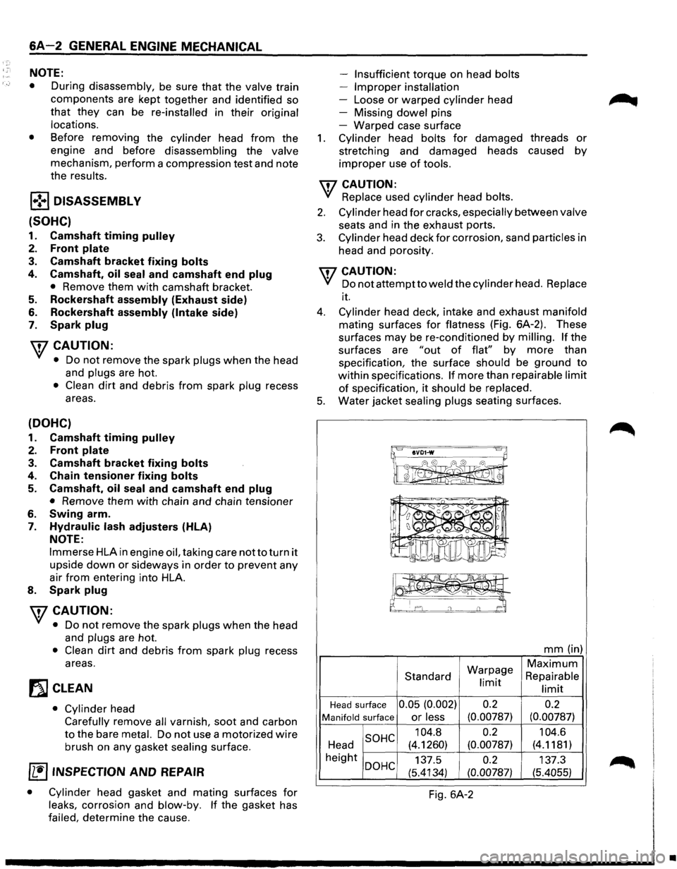
6A-2 GENERAL ENGINE MECHANICAL
NOTE:
•
During disassembly, be sure that the valve train
components are kept
together and identified so
that they can be re-installed in their original
locations.
• Before removing the cylinder head from the
engine and before disassembling the valve
mechanism, perform a compression test and note
the results.
1•! .. 1 DISASSEMBLY
(SOHC)
1. Camshaft timing pulley
2. Front plate
3. Camshaft bracket fixing bolts
4. Camshaft, oil seal and camshaft end plug
• Remove them with camshaft bracket.
5. Rockershaft assembly (Exhaust side)
6. Rockershaft assembly (Intake side)
7. Spark plug
\fl CAUTION:
VI • Do not remove the spark plugs when the head
and plugs are hot.
• Clean dirt and debris from spark plug recess
areas.
(DOHC)
1. Camshaft timing pulley
2. Front plate
3. Camshaft bracket fixing bolts
4. Chain tensioner fixing bolts
5. Camshaft, oil seal and camshaft end plug
• Remove them with chain and chain tensioner
6. Swing arm.
7. Hydraulic lash adjusters (HLA)
NOTE:
Immerse HLA in engine oil, taking care nottoturn it
upside down or sideways in order to prevent any
air
from entering into HLA.
8. Spark plug
\flCAUTION:
VI • Do not remove the spark plugs when the head
and plugs are hot.
• Clean dirt and debris from spark plug recess
areas.
f}l CLEAN
• Cylinder head
Carefully remove
all varnish, soot and carbon
to the bare metal. Do not use a motorized wire
brush on any gasket sealing surface.
IL'~'IINSPECTION AND REPAIR
• Cylinder head gasket and mating surfaces for
leaks, corrosion and blow-by. If the gasket has
failed, determine the cause. Insufficient
torque on head bolts
Improper installation
Loose
or warped cylinder head
Missing
dowel pins
- Warped case surface
1. Cylinder head bolts for damaged threads or
stretching and damaged heads caused by
improper use of tools.
\fl CAUTION:
VI Replace used cylinder head bolts.
2. Cylinder head for cracks, especially between valve
seats and in the exhaust ports.
3. Cylinder head deck for corrosion, sand particles in
head and porosity.
\fl CAUTION:
VI Do not attemptto weld the cylinder head. Replace
it.
4. Cylinder head deck, intake and exhaust manifold
mating surfaces for flatness (Fig. 6A-2). These
surfaces
may be re-conditioned by milling. If the
surfaces are
"out of flat" by more than
specification, the surface should be ground
to
within specifications. If more than repairable limit
of specification, it should be replaced.
5. Water jacket sealing plugs seating surfaces.
IIVD1-w 8~
~ I 0 I ' 0 0 I 0
mm (in)
Warpage
Maximum
Standard Repairable limit limit
Head surface 0.05 (0.002) 0.2
0.2
Manifold surface or less (0.00787) (0.00787)
SOHC 104.8 0.2
104.6
Head (4.1260) (0.00787) (4.1181)
height
DOHC 137.5 0.2 137.3
(5.4134)
(0.00787) (5.4055)
Fig. 6A-2
•
Page 579 of 1928
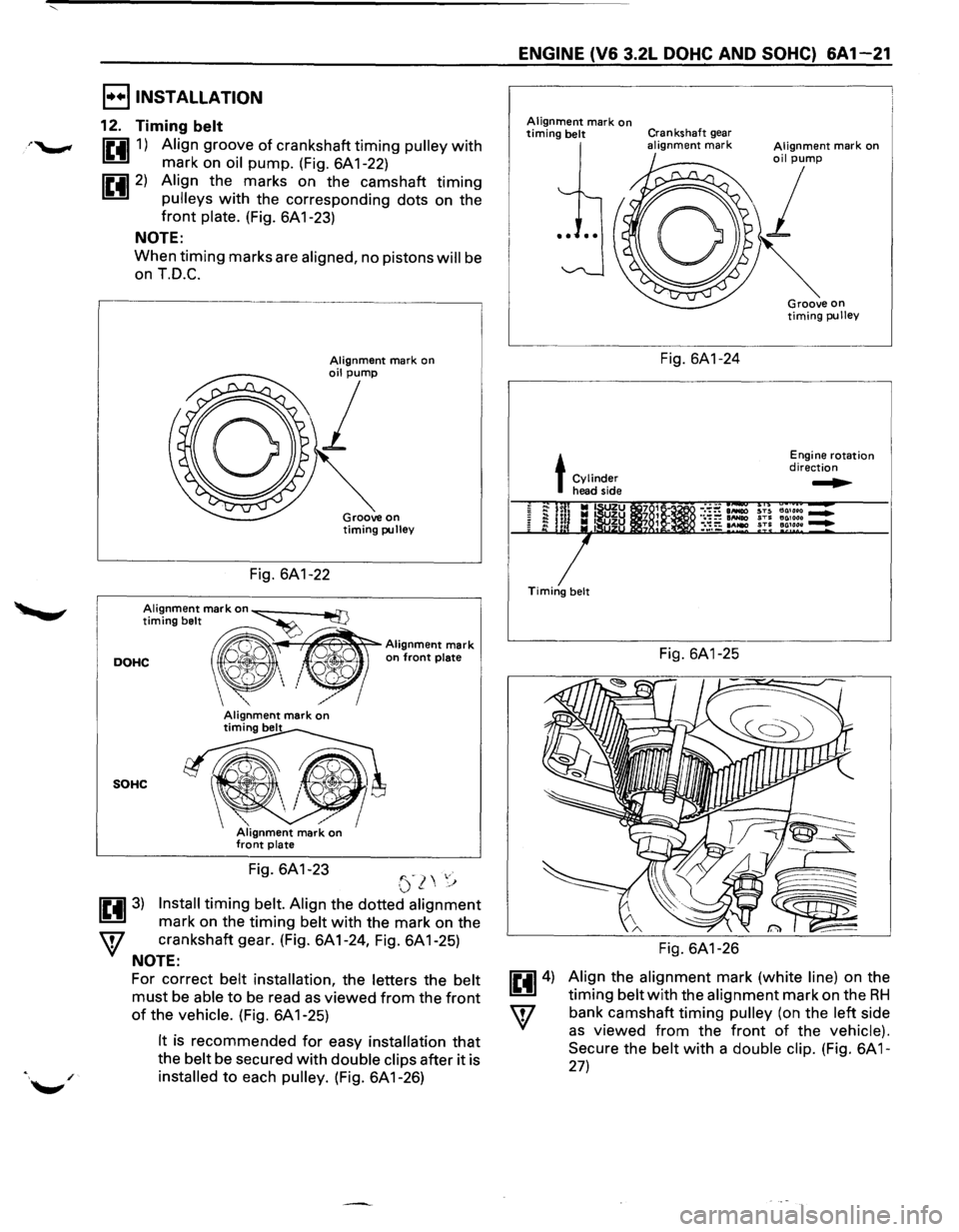
I••IINSTALLATION
12. Timing belt
1£4111) Align groove of crankshaft timing pulley with
mark on oil pump. (Fig. 6A 1-22)
1£4112) Align the marks on the camshaft timing
pulleys with the corresponding dots on the
front plate. (Fig. 6A 1-23)
NOTE:
When timing marks are aligned, no pistons will be
on T.D.C.
,-----------------------------,
Fig. 6A1-22
Groove on timing pulley
Alignment mark on~ ad]
timing belt ·~Alignment mark
DOHC ", ' on front plate Q',
SOHC
Fig. 6A1-23 '"-) ,.· (.)~\,'j
1£4113) Install timing belt. Align the dotted alignment
mark on the timing belt with the mark on the
W crankshaft gear. (Fig. 6A1-24, Fig. 6A1-25)
NOTE:
For correct belt installation, the letters the belt
must be able to be read as viewed from the front
of the vehicle. (Fig. 6A 1-25)
It is recommended for easy installation that
the belt be secured with double clips after it is
installed to each pulley. (Fig. 6A 1-26)
ENGINE (V6 3.2L DOHC AND SOHC) 6A1-21
Alignment mark on timing belt Crankshaft gear alignment mark
L~---
t Cylinder head side
Timing belt
Fig. 6A1-24
Fig. 6A1-25
Fig. 6A1-26
Engine rotation direction
~
Align the alignment mark (white line) on the
timing belt with the alignment mark on the RH
bank camshaft timing pulley (on the left side
as viewed from the front of the vehicle).
Secure
the belt with a double clip. (Fig. 6A 1-
27)