height adjustment ISUZU TROOPER 1995 Workshop Manual
[x] Cancel search | Manufacturer: ISUZU, Model Year: 1995, Model line: TROOPER, Model: ISUZU TROOPER 1995Pages: 1928
Page 133 of 1928
FRONT END ALIGNMENT 3A-1
SECTION3A
FRONT END ALIGNMENT
CAUTION:
When fasteners are removed, always reinstall them at the same location from which they were removed. If
a fastener needs to be replaced, use the correct part number fastener for that application. If the correct part
number fastener is not available, a fastener of equal size and strength (or stronger) may be used. Fasteners
that are not reused, and those requiring thread locking compound will be called out. The correcttorque value
must be used when installing fasteners that require it. If the above conditions are not followed, parts or
system damage could result.
CONTENTS
General Description ................................ 3A-1
Camber Adjustment ............................. 3A-4
Definition of Terms .............................. 3A·2 Toe-in Adjustment ............................... 3A-5
On-Vehicle Service ................................. 3A-3 Maximum Steering Angle Adjustment ....... 3A-5
Inspection ......................................... 3A-3 Main Data and Specifications ..................... 3A-6
Trim Height Adjustment ........................ 3A-3 General Specifications .......................... 3A-6
Caster
Adjustment ............................... 3A-3 Torque Specifications ........................... 3A-6
GENERAL DESCRIPTION
"Front End Alignment" refers to the angular
relationship between the front wheels, the front
suspension attaching parts and the ground.
Proper front end alignment must be maintained in
order to insure efficient steering, good directional
stability and to prevent abnormal tire wear.
The
most important factors of front end alignment are
wheel toe-in, wheel camber and axle caster.
Page 135 of 1928
FRONT END ALIGNMENT 3A-3
ON-VEHICLE SERVICE
INSPECTION
Before making any adjustments affecting caster,
camber or toe-in, the following front end inspection
should be made.
I L•IINSPECT
1. Tires for proper inflation pressure. Refer to
"Wheels and Tires" in section 3E.
2. Front wheel bearings for proper adjustment.
Refer to "Front Wheel Drive" in section 4C.
3. Ball joints, tie rod ends and relay rods. If
excessive looseness is noted, correct before
adjusting. Refer
to "Steering Linkage" in section
3B3.
4. Wheel and tires for run-out. Refer to "Wheels
and Tires" in section 3E.
5. Trim height. If not within specifications, the
correction
must be made before adjusting caster.
6. Steering gear for looseness at the frame.
7. Shock absorbers for leaks or any noticeable
noise.
Refer
to "Front Suspension" in section 3C.
8. Control arms or stabilizer bar attachment for
looseness. Refer to "Front Suspension" in section
3C.
9. Alignment equipment. Follow the manufacturer's
instructions.
10. Level of the vehicle. The vehicle must be on a
level surface.
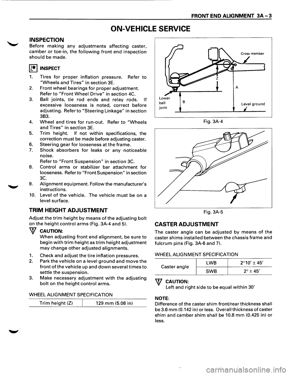
TRIM HEIGHT ADJUSTMENT
Adjust the trim height by means of the adjusting bolt
on the height control arms (Fig. 3A-4 and 5).
W CAUTION:
When adjusting front end alignment, be sure to
begin with trim height as trim height adjustment
may change other adjusted alignments.
1. Check and adjust the tire inflation pressures.
2. Park the vehicle on a level ground and move the
front of the vehicle up and down several times to
settle the suspension.
3. Make necessary adjustment with the adjusting
bolt on the height control arms.
WHEEL
ALIGNMENT SPECIFICATION
Trim height (Z) 129 mm (5.08 in)
Lower
ball joint
B
Fig. 3A-4
Fig. 3A-5
CASTER ADJUSTMENT
Level ground
The caster angle can be adjusted by means of the
caster shims installed between the chassis frame and
fulcrum pins (Fig. 3A-6 and 7).
WHEEL
ALIGNMENT SPECIFICATION
LWB
Caster angle
SWB
W CAUTION:
Left and right side to be equal within 30'
NOTE:
Difference of the caster shim front/rear thickness shall
be 3.6
mm (0.142 in) or less. Overall thickness of caster
shim and camber shim shall be 10.8 mm (0.425 in) or
less.
Page 333 of 1928
HYDRAULIC BRAKES SA-13
BRAKE PEDAL ASSEMBL V
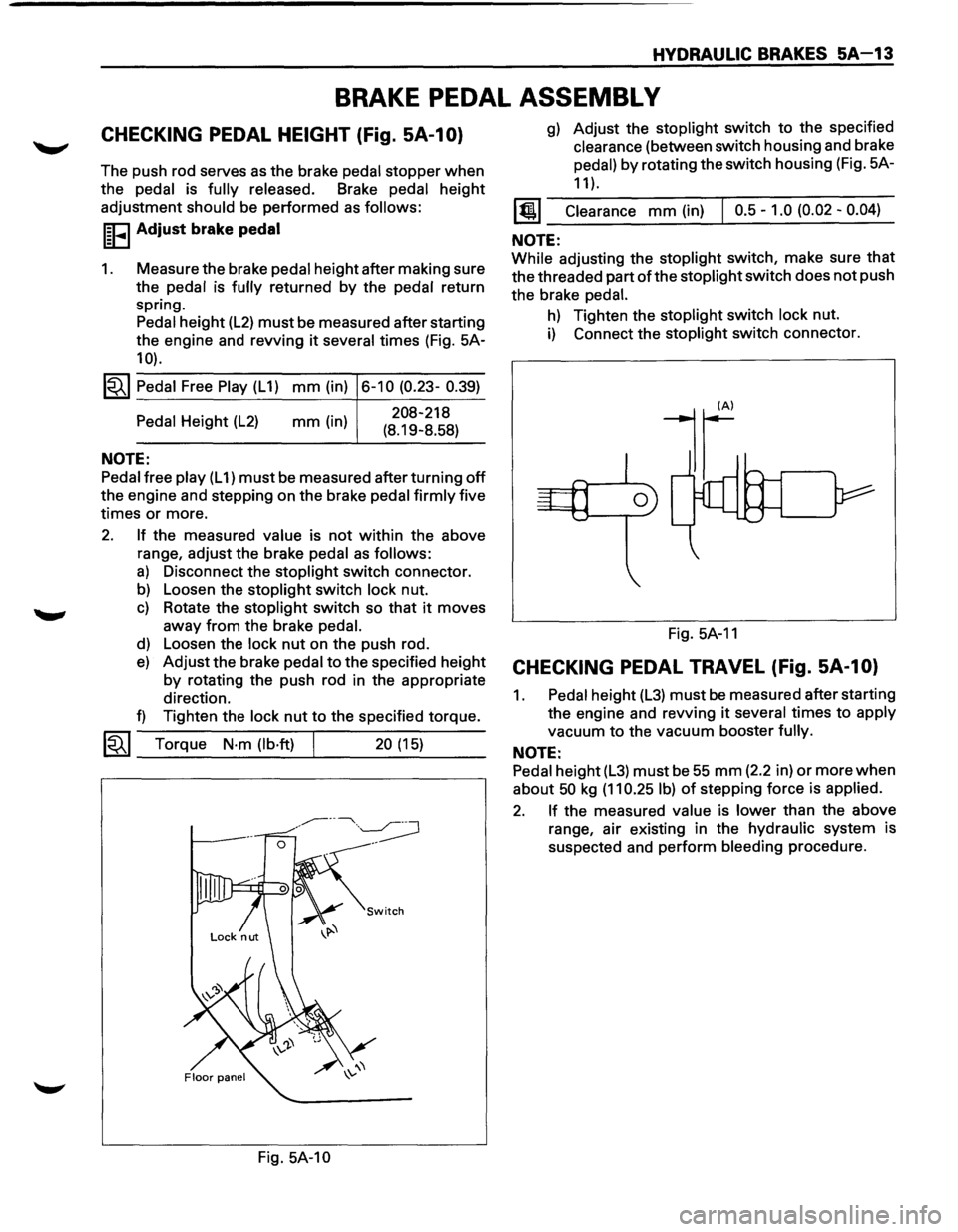
CHECKING PEDAL HEIGHT (Fig. SA-1 0)
The push rod serves as the brake pedal stopper when
the pedal is fully released. Brake pedal height
adjustment
should be performed as follows:
I~FI Adjust brake pedal
1. Measure the brake pedal height after making sure
the pedal is
fully returned by the pedal return
spring. Pedal height
(L2) must be measured after starting
the engine and revving
it several times (Fig. 5A-
10).
1~1 Pedal Free Play (L 1) mm (in) 6-10 (0.23- 0.39)
Pedal Height (L2)
NOTE:
mm (in) 208-218
(8.19-8.58)
Pedal free play (L 1) must be measured after turning off
the engine and stepping on the brake pedal firmly five
times
or more.
2. If the measured value is not within the above
range, adjust the brake
pedal as follows:
a) Disconnect the stoplight switch connector.
b) Loosen the stoplight switch lock nut.
c) Rotate the stoplight switch so that it moves
away
from the brake pedal.
d) Loosen the lock nut on the push rod.
e) Adjust the brake pedal to the specified height
by rotating the push rod in the appropriate
direction.
f) Tighten the lock nut to the specified torque.
~~~ Torque N·m (lb·ft) 20 (15) --------~----~---
Fig. 5A-10
g) Adjust the stoplight switch to the specified
clearance (between switch housing and brake
pedal)
by rotating the switch housing (Fig. 5A-
11 ).
1@1 Clearance mm (in) I 0.5-1.0 (0.02-0.04)
NOTE:
While adjusting the stoplight switch, make sure that
the threaded part of the stoplight switch does not push
the brake
pedal.
h) Tighten the stoplight switch lock nut.
i) Connect the stoplight switch connector.
Fig.
5A-11
CHECKING PEDAL TRAVEL (Fig. SA-1 0)
1. Pedal height (L3) must be measured after starting
the engine and revving
it several times to apply
vacuum
to the vacuum booster fully.
NOTE:
Pedal height (L3) must be 55 mm (2.2 in) or more when
about 50 kg (11 0.25 I b) of stepping force is applied.
2. If the measured value is lower than the above
range, air existing in the hydraulic system is
suspected and perform bleeding procedure.
Page 1148 of 1928
7C 14 CLUTCH
1••1 REMOVAL
1. Pin and jaw joint pin
2. Pedal assembly and switch
3. Oil line pipe
4. Slave cylinder assembly and heat protector
5. Master cylinder assembly
6. Damper cylinder assembly
ll.•l INSPECTION AND REPAIR
Make necessary adjustments, repairs, and part
replacement
if wear, damage or other problems are
discovered during inspection.
1••1 INSTALLATION
To install, follow the removal steps in the reverse
order, noting the
following points:
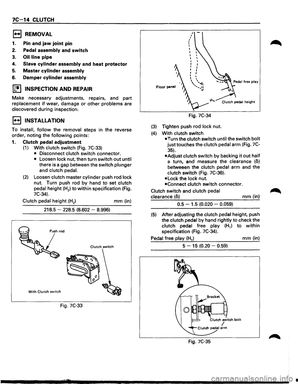
1. Clutch pedal adjustment
(1) With clutch switch (Fig. 7C-33)
• Disconnect clutch switch connector.
• Loosen lock nut, then turn switch out until
there is a gap between the switch plunger
and
clutch pedal.
(2) Loosen clutch master cylinder push rod lock
nut. Turn push rod by hand to set clutch
pedal height (H2) to
within specification (Fig.
7C-34).
Clutch
pedal height (H2 ) mm (in)
218.5
-228.5 (8.602 -8.996)
Clutch switch
With Clutch switch
Fig. 7C-33
Floor panel
Fig. 7C-34
(3) Tighten push rod lock nut.
(4) With clutch switch
Clutch pedal height
•Turn the clutch switch until the switch bolt
justtouches the clutch pedal arm (Fig. 7C
:~5).
•Adjust clutch switch by backing it out half
a
turn, and measure the clearance (o)
betweeen the clutch pedal arm and the
c:lutch switch (Fig. 7C-36).
•Lock the lock nut.
•Connect clutch switch connector.
Clutch switch and clutch
pedal
clearance
(o) mm (in)
0.5 -1.5 (0.020 -0.059)
(5) After adjusting the clutch pedal height, push
the clutch pedal
by hand rightly to check the
clutch pedal free play (H1) to within
specification (Fig. 7C-34).
Pedal free play (H1) mm (in)
5 -
15 (0.20 -0.59)
Fig. 7C-35
•