fuel cap release ISUZU TROOPER 1995 Workshop Manual
[x] Cancel search | Manufacturer: ISUZU, Model Year: 1995, Model line: TROOPER, Model: ISUZU TROOPER 1995Pages: 1928
Page 751 of 1928
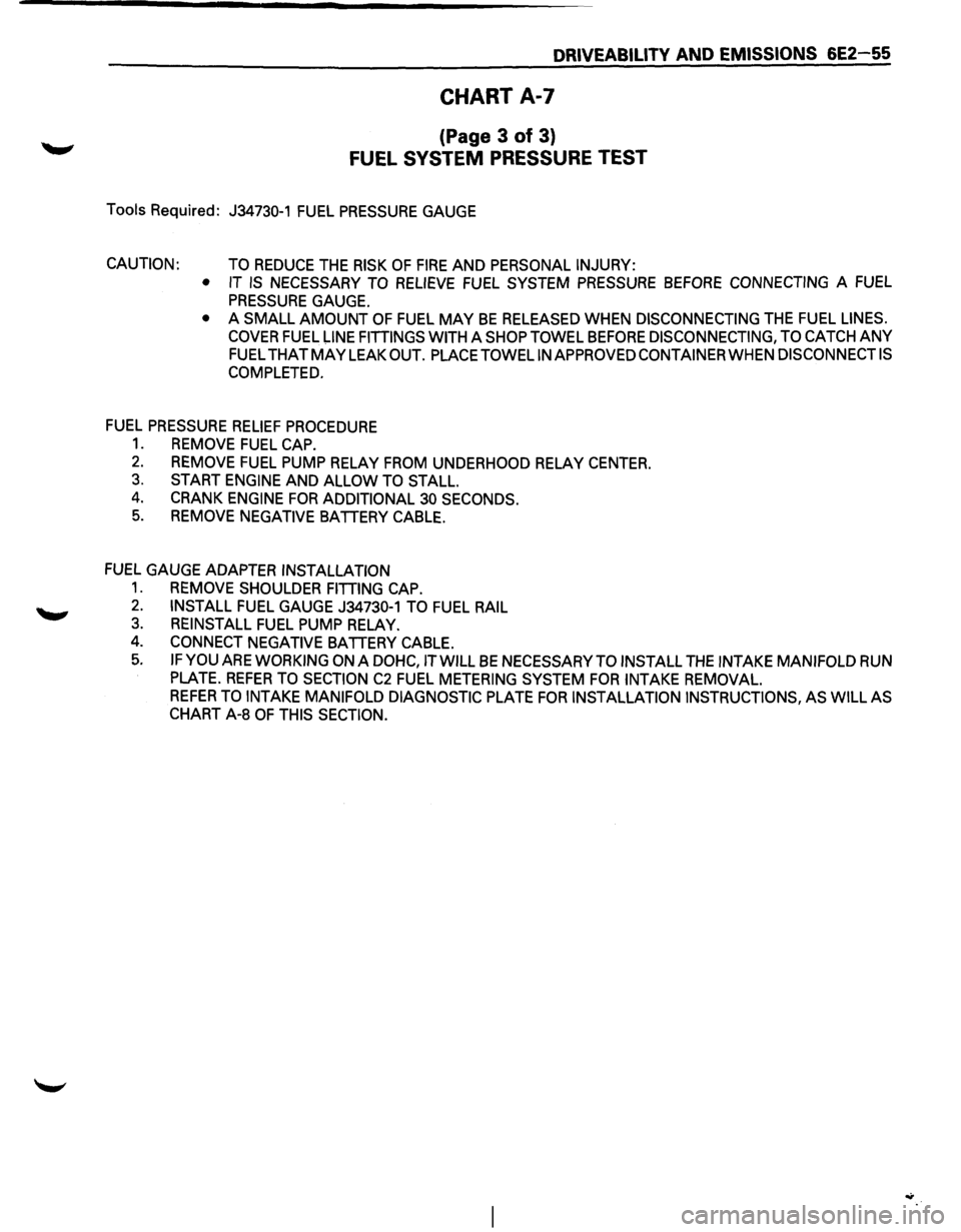
DRIVEABILITY AND EMISSIONS 6E2-55
CHART A-7
(Page 3 of 3)
FUEL SYSTEM PRESSURE TEST
Tools Required: J34730-1 FUEL PRESSURE GAUGE
CAUTION: TO REDUCE THE RISK OF FIRE AND PERSONAL INJURY:
• IT
IS NECESSARY TO RELIEVE FUEL SYSTEM PRESSURE BEFORE CONNECTING A FUEL
PRESSURE GAUGE.
• A SMALL AMOUNT OF FUEL MAY BE RELEASED WHEN DISCONNECTING THE FUEL LINES.
COVER FUEL l-INE FITTINGS WITH A SHOP TOWEL BEFORE DISCONNECTING, TO CATCH ANY
FUEL THATMAYLEAKOUT. PLACETOWELINAPPROVEDCONTAINERWHENDISCONNECTIS
COMPLETED.
FUEL PRESSURE
RELIEF PROCEDURE
1. REMOVE FUEL CAP.
2. REMOVE FUEL PUMP RELAY FROM UNDERHOOD RELAY CENTER.
3. START
ENGINE AND ALLOW TO STALL.
4. CRANK ENGINE FOR ADDITIONAL 30 SECONDS.
5. REMOVE NEGATIVE BATTERY CABLE.
FUEL GAUGE ADAPTER
INSTALLATION
1. REMOVE SHOULDER FITTING CAP.
2. INSTALL FUEL GAUGE J34730-1 TO FUEL RAIL
3. REINSTALL FUEL PUMP RELAY.
4. CONNECT NEGATIVE BATTERY CABLE.
5. IF YOU ARE WORKING ON A DOHC, IT WILL BE NECESSARY TO INSTALL THE INTAKE MANIFOLD RUN
PLATE.
REFER TO SECTION C2 FUEL METERING SYSTEM FOR INTAKE REMOVAL.
REFER TO INTAKE MANIFOLD DIAGNOSTIC PLATE FOR INSTALLATION INSTRUCTIONS, AS WILL AS
CHART A-8 OF THIS SECTION.
Page 818 of 1928
6E2-122 DRIVEABILITV AND EMISSIONS
INDUCTION AIR CONTROL PLATE
SYSTEM
Refer to CHART C-2D to diagnose the Induction air
control plate system.
ON-VEHICLE SERVICE
FUEL PUMP RELAY
The fuel pump relay is mounted in the engine
compartment.
Other than checking for loose
connectors, the only service possible is replacement.
MUL TIPORT FUEL INJECTION
COMPONENTS
WCAUTION:
VI • To reduce the risk of fire and personal injury, it
is necessary to relieve the fuel system pressure
before servicing
fuel system components.
• After relieving system pressure, a small
amount of fuel may be released when servicing
fuel lines or connections. In order to reduce the
chance
of personal injury, cover fuel line
fittings with a shop towel before disconnecting,
to catch any
fuel that may leak out. Place the
towel in an approved container when
disconnect is completed.
Fuel Pressure Relief Procedure
1. Remove fuel cap.
2. Remove fuel pump relay from underhood relay
box.
3. Start engine and allow to stall.
4. Crank engine for additional 30 seconds.
5. Remove negative battery cable.
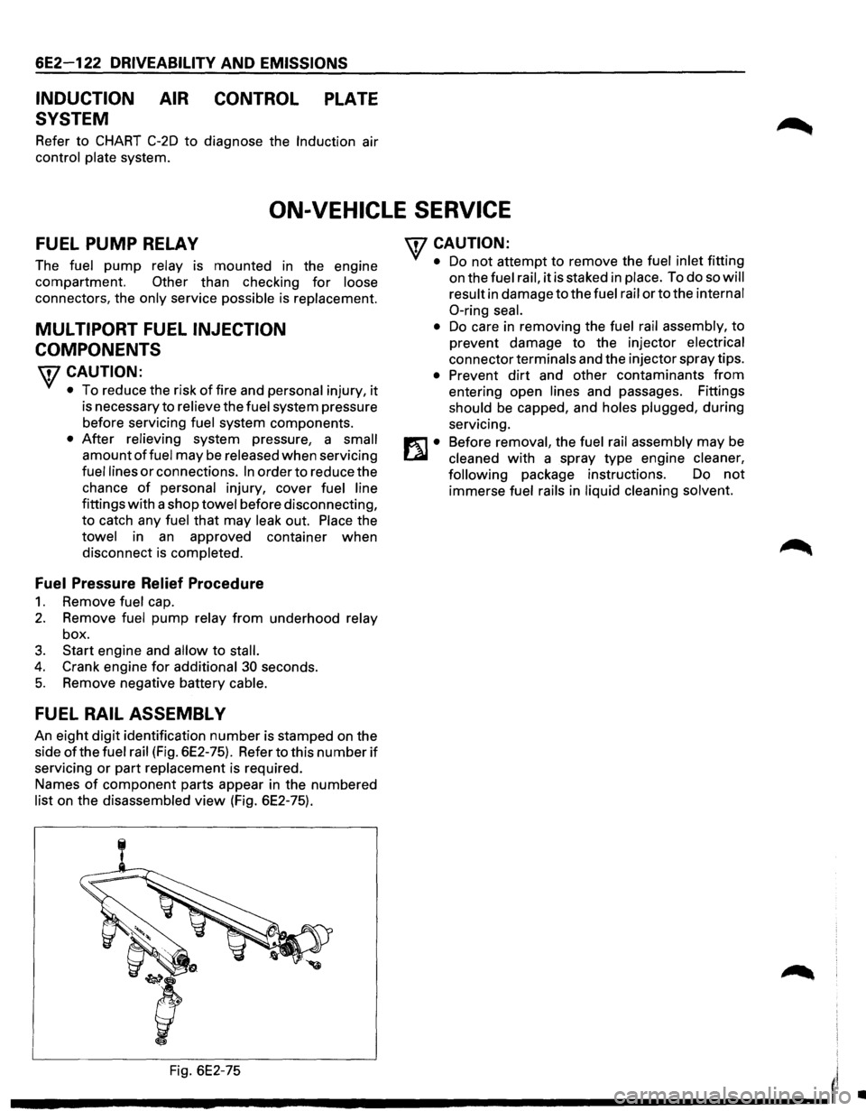
FUEL RAIL ASSEMBL V
An eight digit identification number is stamped on the
side
ofthe fuel rail (Fig. 6E2-75). Refer to this number if
servicing or part replacement is required.
Names
of component parts appear in the numbered
list on the disassembled view (Fig. 6E2-75).
'fCAUTION:
• Do not attempt to remove the fuel inlet fitting
on the
fuel rail, it is staked in place. To do so will
result
in damage to the fuel rail or to the internal
0-ring seal.
•
Do care in removing the fuel rail assembly, to
prevent damage to the injector
electrical
connector terminals and the injector spray tips.
• Prevent dirt and other contaminants from
entering open lines and passages. Fittings
should be capped, and holes plugged, during
servicing.
Before
removal, the fuel rail assembly may be
cleaned with a spray type engine cleaner,
following
package instructions. Do not
immerse fuel rails in liquid cleaning solvent.
Fig. 6E2-75
I'
---------------------'
•