load capacity ISUZU TROOPER 1995 Workshop Manual
[x] Cancel search | Manufacturer: ISUZU, Model Year: 1995, Model line: TROOPER, Model: ISUZU TROOPER 1995Pages: 1928
Page 201 of 1928
WHEELS AND TIRES 3E-1
SECTION 3E
WHEELS AND TIRES
W CAUTION:
When fasteners are removed, always reinstall them at the same location from which they were removed.
If a fastener needs to be replaced, use the correct part number fastener for that application. If the correct
part
number fastener is not available, a fastener of equal size and strength (or stronger) may be used.
Fasteners
that are not reused, and those requiring thread locking compound, will be called out. The correct
torque value must be used when installing fasteners that require it. If the above conditions are not
followed, parts or system damage could result.
CONTENTS
General Description . . . . . . . . . . . . . . . . . . . . . . . . . . . . . . . 3 E -1 Unit Repair .......................................... 3E-7
Diagnosis ........................................... 3E-2 Tires ............................................... 3E-7
Irregular and Premature Wear ................ 3E-2 Wheels ............................................ 3E-7
Inflation of Tires ................................. 3 E- 3 General Balance Procedure ................... 3E-8
Diagnosis List. . . . . . . . . . . . . . . . . . . . . . . . . . . . . . . . . . . . 3 E- 3 Balancing Wheel and Tire ...................... 3E-8
On-Vehicle Service ................................ 3E-6 Main Data and Specifications .................... 3E-9
Wheels ............................................ 3E-6 General Specifications ......................... 3E-9
Torque Specifications .......................... 3E-9
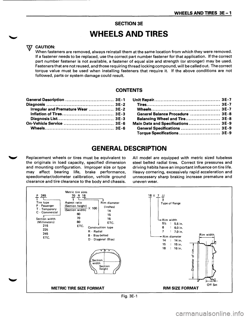
GENERAL DESCRIPTION
Replacement wheels or tires must be equivalent to
the originals in load capacity, specified dimension
and mounting configuration. Improper size or type
may affect bearing life, brake performance,
speedometer/odometer calibration, vehicle ground
clearance and tire clearance to the body and chassis.
p 245
T Tire type P -Passenger T -Temporary C -Commercial
Section
width (Millimeters) 215 225
245
ETC.
Metric tire sizes 70 R 16 T ,...
Aspect ratio I Rim diameter
(Section height)
(Section
width) X 100 (Inches)
14 60 70
80 ETC.
15
16 ETC.
Construction type
R-Radial
B - Bias-belted
D - Diagonal (Bias)
METRIC TIRE SIZE FORMAT
All model are equipped with metric sized tubeless
steel belted radial
tires. Correct tire pressures and
driving habits have an important influence on tire life.
Heavy cornering, excessively rapid acceleration and
unnecessary sharp braking increase
premature and
uneven wear.
16 X 7 JJ
I
~pe of flange
Rim width 5% 5.5 in.
6 6.0 in. 7 7.0 in.
Rim diameter Rim width
14 14 in. 15 15 in. 16 : 16 in.
I Off Set RIM SIZE FORMAT
Fig. 3E-1
Page 658 of 1928
601-4 ENGINE ELECTRICAL
'IT7 WARNING:
'if Never attach the end of the jumper cable
directly
to the negative terminal of the dead
battery.
5. Start the engine of the vehicle with the good
battery.
Make sure that
all unnecessary electrical acces
sories have been turned
"OFF".
6. Start the engine of the vehicle with the dead
battery.
7. To remove the jumper cables, follow the above
directions in the reverse order.
Be sure to first disconnect the negative cable
from the vehicle with the discharged battery.
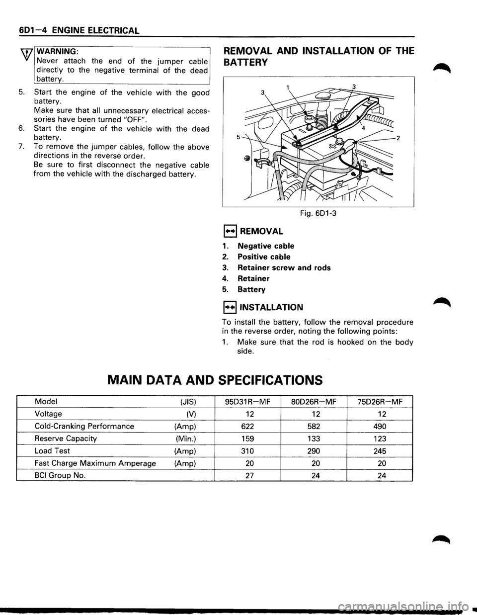
REMOVAL AND INSTALLATION OF THE
BATTERY
5
Fig. 601-3
1+•1 REMOVAL
1. Negative cable
2. Positive cable
3. Retainer screw and rods
4. Retainer
5. Battery
I••IINSTALLATION
To install the battery, follow the removal procedure
in the reverse order, noting the
following points:
1. Make sure that the rod is hooked on the body
side.
MAIN DATA AND SPECIFICATIONS
Model
(JIS) 95D31R-MF 80D26R-MF 75D26R-MF
Voltage (V) 12 12 12
Cold-Cranking Performance (Amp)
622 582 490
Reserve Capacity
(Min.)
159 133
123
Load Test
(Amp)
310 290 245
Fast Charge
Maximum Amperage
(Amp) 20 20 20
BCI Group No. 27 24 24
..
Page 861 of 1928
DRIVEABILITV AND EMISSIONS 6E2-165
DIAGNOSIS
FUNCTIONAL CHECK OF POSITIVE
CRANKCASE VENTILATION (PCV)
If an engine is idling rough, check for a clogged PCV or
plugged hose. Replace as required. Use the following
procedure.
1. Remove PCV from rocker arm cover.
2. Run the engine at idle.
3. If there is no vacuum at valve, check for plugged
hoses or manifold port, or PCV.
Replace plugged or deteriorated hoses.
4. Stop the engine and remove PCV. Remove
PCV hose. Inspect metered orifice for being
restricted or
plugged. If restricted clean orifice.
With this system, any
blow-by in excess of the system
capacity (from a
badly-worn engine, sustained heavy
load, etc.) is exhausted into the intake manifold and is
drawn into the engine. Proper
operation
of the PCV System is dependent
upon a
sealed engine. If oil sledging or dilution is
noted, and the PCV System is functioning properly,
malfunction
indicator lamp for possible cause and
correct to ensure that system
will function as intended.
RESULTS OF INCORRECT OPERATION
A plugged valve or hose may cause:
• Rough idle.
• Stalling
or slow idle speed.
• Oil leaks.
• Oil
in air cleaner.
• Sludge
in engine.
ON-VEHICLE SERVICE
An engine which is operated without any crankcase
ventilation can be damaged. Periodically, inspect the
PCV, hoses
and clamps and replace any showing
signs
of deterioration.
Page 1192 of 1928
-·*; ~---
8-2 CHASSIS ELECTRICAL
GENERAL INFORMATION
The chassis electrical system is of 12-volt specifications with a negative ground polarity.
Wire sizes are appropriate
to respective circuits, and classified by color. (The classification of harnesses by
color is shown on the circuit diagram for ease of harness identification.)
The
wire size is determined by load capacity and the length of wire required.
The
vehicle harnesses are: body harness, chassis harness, engine room harness, instrument harness,
transmission harness, engine
ECGI harness, dome light harness, door harness, rear body harness, tailgate
harness,
SRS harness and battery cables.
The harnesses are protected either
by tape or corrugated tube, depending on harness location.
The circuit
for each system consists of the power source, wire, fuse, relay, switch, load parts and ground, all of
which are shown on the circuit diagram.
In this manual, each electrical device is classified by system. For major parts shown on the circuit based on
the circuit diagram
for each system, a summary, diagnosis oftroubles, inspection and removal and installation
procedures are detailed.
NOTES FOR WORKING ON ELECTRICAL ITEMS
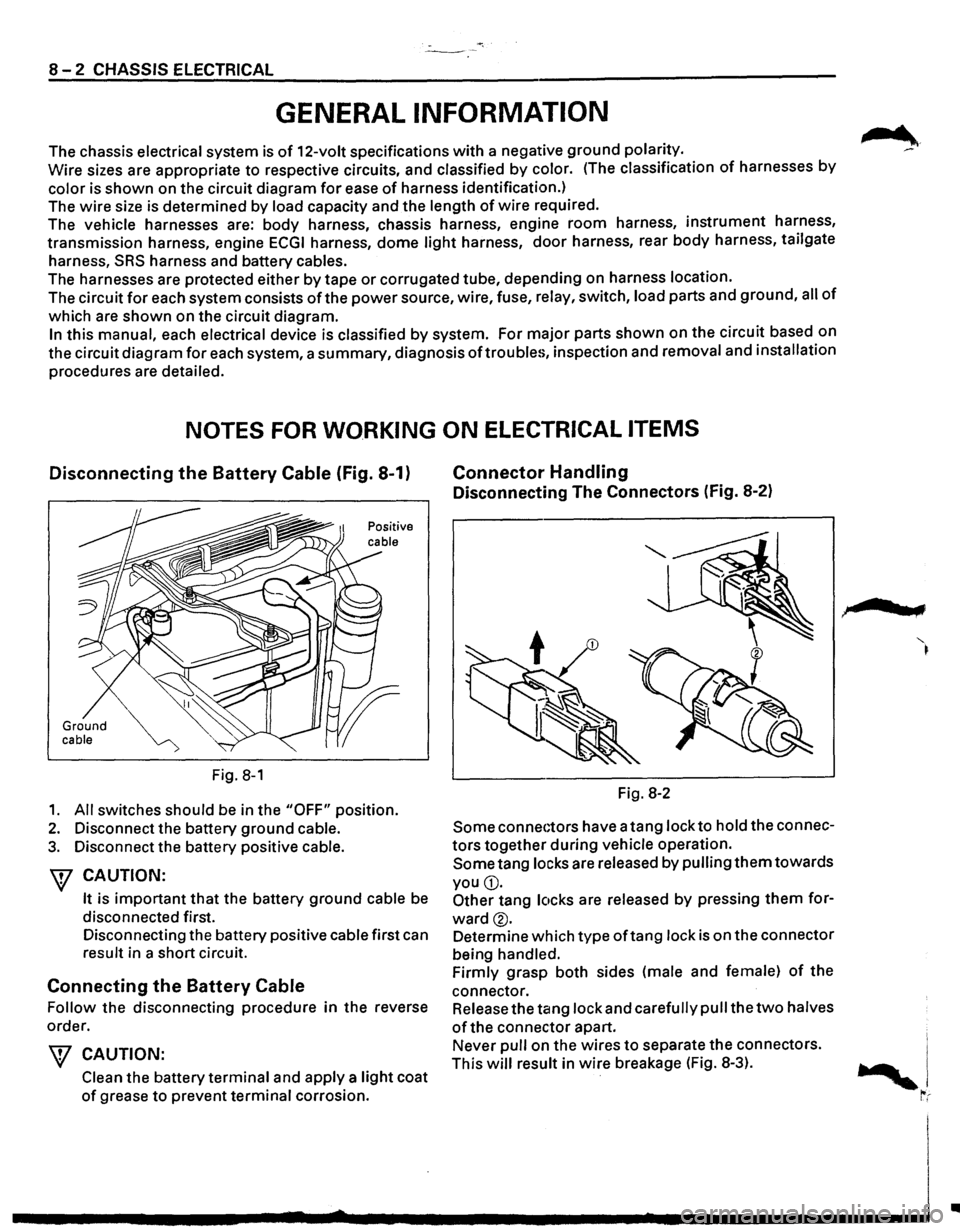
Disconnecting the Battery Cable (Fig. 8-1)
Ground cable
Fig. 8-1
1. All switches should be in the "OFF" position.
2. Disconnect the battery ground cable.
3. Disconnect the battery positive cable.
W CAUTION:
It is important that the battery ground cable be
disconnected first.
Disconnecting the battery positive cable first can
result in a short circuit.
Connecting the Battery Cable
Follow the disconnecting procedure in the reverse
order.
\V CAUTION:
Clean the battery terminal and apply a light coat
of grease to prevent terminal corrosion.
Connector Handling
Disconnecting The Connectors (Fig. 8-2)
Fig. 8-2
Some connectors have a tang lock to hold the connec
tors together during vehicle operation.
Some tang locks are released by pulling them towards
you
G).
Other tang locks are released by pressing them for
ward®.
Determine which type oftang lock is on the connector
being handled.
Firmly grasp both sides (male and female)
of the
connector. Release the tang lock and carefully pull the
two halves
of the connector apart.
Never pull on the wires
to separate the connectors.
This
will result in wire breakage (Fig. 8-3).
.,
..
Page 1201 of 1928
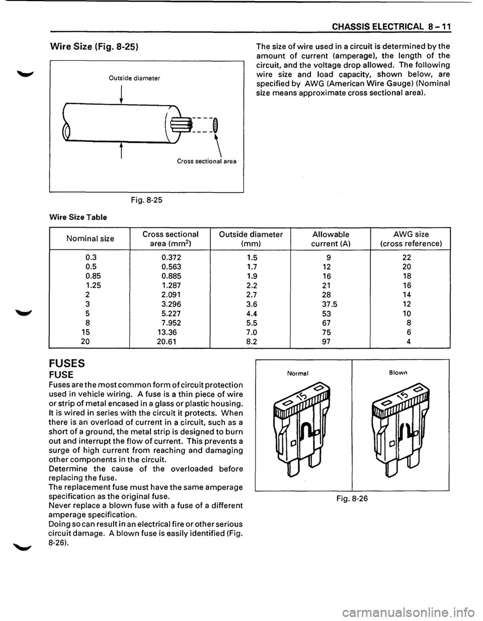
Wire Size (Fig. 8-25)
Outside diameter
Fig. 8-25
Wire Size Table
----,
Cross sectional area
CHASSIS ELECTRICAL 8 -11
The size of wire used in a circuit is determined by the
amount of current (amperage), the length of the
circuit, and the voltage drop allowed. The following
wire size and load capacity, shown below, are
specified
by AWG (American Wire Gauge) (Nominal
size means approximate cross sectional area).
Nominal size Cross sectional
Outside diameter Allowable AWG size
area
(mm2 ) (mm)
0.3
0.5
0.85
1.25
2
3
5 8
15
20
FUSES
FUSE
0.372
0.563
0.885
1.287
2.091
3.296
5.227
7.952
13.36
20.61
Fuses are the most common form of circuit protection
used in vehicle wiring. A fuse is a thin piece of wire
or strip of metal encased in a glass or plastic housing.
It is wired in series with the circuit it protects. When
there is an overload of current in a circuit, such as a
short of a ground, the metal strip is designed to burn
out and interrupt the flow of current. This prevents a
surge
of high current from reaching and damaging
other components in the circuit.
Determine the cause of the overloaded before
replacing the fuse.
The
replacement fuse must have the same amperage
specification as the original fuse.
Never replace a blown fuse with a fuse of a different
amperage specification.
Doing so can result in an electrical fire or other serious
circuit damage. A blown fuse is easily identified (Fig.
8-26). 1.5
1.7
1.9
2.2
2.7
3.6 4.4
5.5
7.0
8.2
current (A) (cross
reference)
9
22
12 20
16 18
21 16
28 14
37.5
12
53 10
67 8
75 6
97 4
Normal Blown
Fig.
8-26
Page 1202 of 1928
8-12 CHASSIS ELECTRICAL
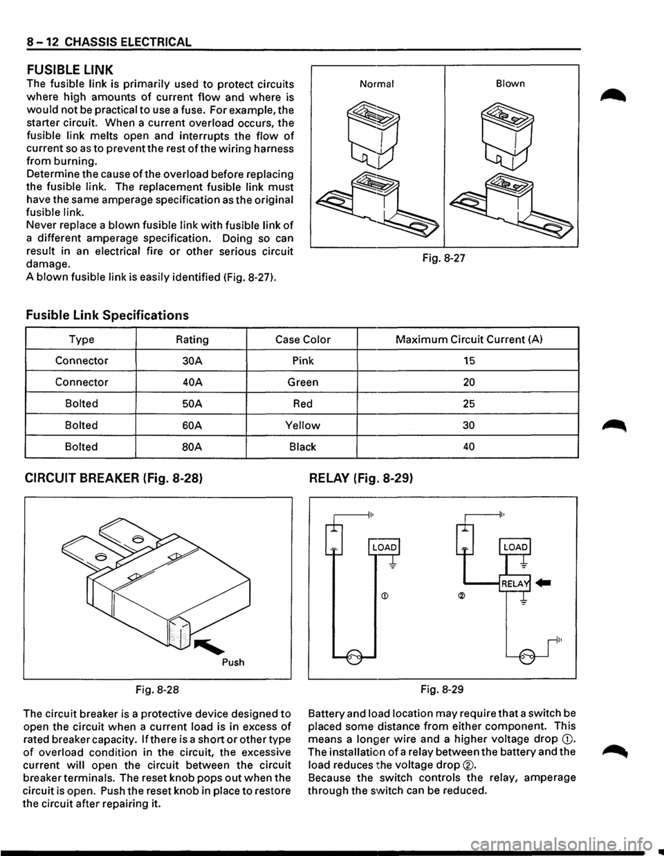
FUSIBLE LINK
The fusible link is primarily used to protect circuits
where high amounts
of current flow and where is
would not be practical to use a fuse. For example, the
starter circuit. When a current
overload occurs, the
fusible link melts open and interrupts the flow of
current so as to prevent the rest of the wiring harness
from burning.
Determine the cause
ofthe overload before replacing
the fusible link. The replacement fusible link must
have the same amperage specification as the original
fusible link.
Never replace a blown fusible link with fusible link of
a different amperage specification. Doing so can
result in an electrical fire or other serious circuit
damage.
A
blown fusible link is easily identified (Fig. 8-27).
Fusible Link Specifications
Normal Blown
Fig.
8-27
Type Rating
Case Color Maximum Circuit Current (A)
Connector
30A Pink 15
Connector 40A Green 20
Bolted 50 A Red 25
Bolted 60A Yellow 30
Bolted
BOA Black 40
CIRCUIT BREAKER (Fig. 8-28)
Push
Fig. 8-28
The circuit breaker is a protective device designed
to
open the circuit when a current load is in excess of
rated breaker capacity. If there is a short or other type
of overload condition in the circuit, the excessive
current
will open the circuit between the circuit
breaker
terminals. The reset knob pops out when the
circuit is open. Push the reset knob in
place to restore
the circuit after repairing it.
RELAY (Fig. 8-29)
Fig. 8-29
Battery and
load location may require that a switch be
placed some distance from either component. This
means a
longer wire and a higher voltage drop G).
The installation of a relay between the battery and the
load reduces the voltage drop®.
Because the switch controls the relay, amperage
through the switch can be reduced.
..
Page 1213 of 1928
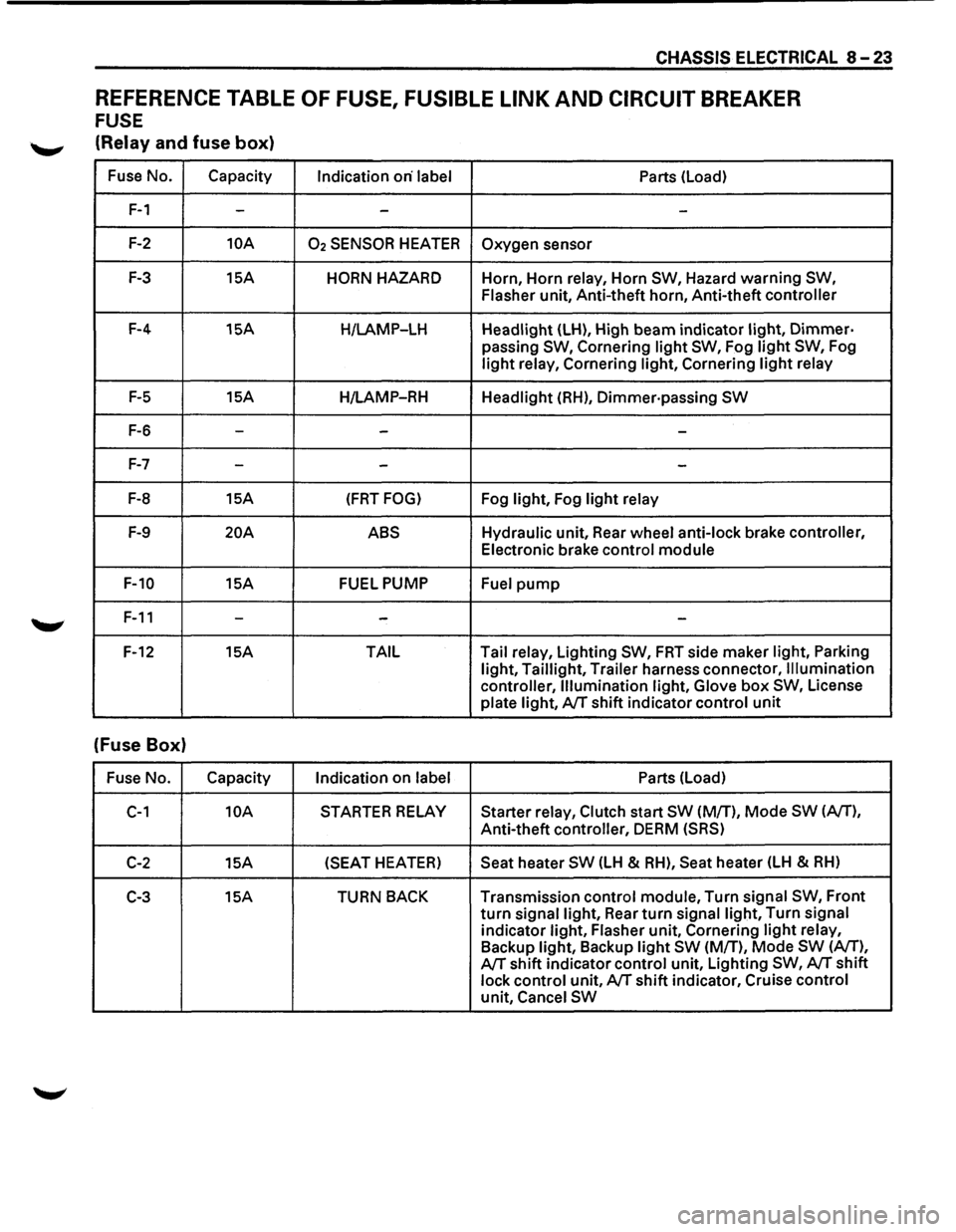
CHASSIS ELECTRICAL 8-23
REFERENCE TABLE OF FUSE, FUSIBLE LINK AND CIRCUIT BREAKER
FUSE
'--"' (Relay and fuse box)
Fuse No. Capacity
Indication on· label Parts (Load)
F-1 --
-
F-2 10A 02 SENSOR HEATER Oxygen sensor
F-3 15A HORN HAZARD Horn, Horn relay, Horn SW, Hazard warning SW,
Flasher
unit, Anti-theft horn, Anti-theft controller
F-4 15A
H/LAMP-LH Headlight (LH), High beam indicator light, Dimmer·
passing SW, Cornering light SW, Fog light SW, Fog
light relay, Cornering light, Cornering light relay
F-5 15A
H/LAMP-RH Headlight (RH), Dimmer·passing SW
F-6 ---
F-7 --
-
F-8 15A (FRT FOG) Fog light, Fog light relay
F-9 20A ABS Hydraulic unit, Rear wheel anti-lock brake controller,
Electronic brake control module
F-10 15A FUEL PUMP
Fuel pump
F-11 ---
F-12 15A TAIL Tail
relay, Lighting SW, FRT side maker light, Parking
light, Taillight, Trailer harness connector, Illumination
controller, Illumination light, Glove
box SW, License
plate light, A/T shift indicator control unit
(Fuse Box)
Fuse No. Capacity
Indication on label Parts (Load)
C-1 10A STARTER RELAY Starter relay, Clutch start SW (M/T), Mode SW (A/T),
Anti-theft controller, DERM (SRS)
C-2 15A (SEAT
HEATER) Seat heater SW (LH & RH), Seat heater (LH & RH)
C-3 15A TURN BACK Transmission control module, Turn signal SW, Front
turn signal light, Rear turn signal light, Turn signal
indicator light, Flasher unit, Cornering light relay,
Backup light, Backup light SW (M/T), Mode SW (A/T),
A/T shift indicator control unit, Lighting SW, A/T shift
lock control unit, A/T shift indicator, Cruise control
unit, Cancel SW
Page 1214 of 1928
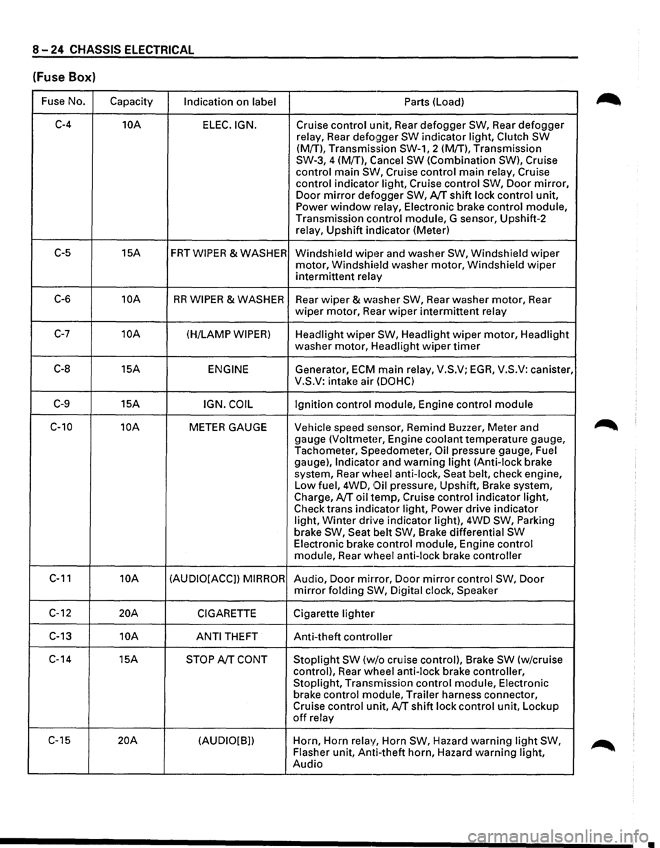
8-24 CHASSIS ELECTRICAL
(Fuse Box)
Fuse No.
Capacity Indication on label Parts (Load)
C-4 10A
ELEC.IGN. Cruise control unit, Rear defogger SW, Rear defogger
relay, Rear
defo9ger SW indicator light, Clutch SW
(M{T), Transmission SW-1, 2 (M!T), Transmission
SW-3, 4 (M{T), Cancel
SW (Combination SW), Cruise
control main
SW, Cruise control main relay, Cruise
control indicator light, Cruise control
SW, Door mirror,
Door mirror defogger SW, AfT shift lock control unit,
Power window relay, Electronic brake control module,
Transmission control module, G sensor, Upshift-2
relay, Upshift indicator (Meter)
C-5 15A FRTWIPER &WASHER
Windshield wipt~r and washer SW, Windshield wiper
motor, Windshit~ld washer motor, Windshield wiper
intermittent relay
C-6 10A RR WIPER & WASHER
Rear wiper & washer SW, Rear washer motor, Rear
wiper motor, Rear wiper intermittent relay
C-7 10A (H/LAMP WIPER) Headlight wiper SW, Headlight wiper motor, Headlight
washer motor, Headlight
wiper timer
C-8 15A ENGINE Generator, ECM main relay, V.S.V; EGA, V.S.V: canister,
V.S.V: intake air
(DOHC)
C-9 15A IGN. COIL Ignition control module, Engine control module
C-10 10A METER GAUGE Vehicle speed stmsor, Remind Buzzer, Meter and
gauge
(Voltmeter, Engine coolant temperature gauge,
Tachometer, Speedometer,
Oil pressure gauge, Fuel
gauge),
Indicator and warning light (Anti-lock brake
system, Rear wheel anti-lock, Seat belt, check engine,
Low fuel, 4WD,
Oil pressure, Upshift, Brake system,
Charge,
AfT oil temp, Cruise control indicator light,
Check trans indicator light,
Power drive indicator
light,
Winter drive indicator light), 4WD SW, Parking
brake SW, Seat belt SW, Brake differential SW
Electronic brake control module, Engine control
module, Rear wheel anti-lock brake controller
C-11 10A (AUDIO[ACCJ) MIRROR Audio, Door mirror, Door mirror control SW, Door
mirror folding SW, Digital clock, Speaker
C-12 20A CIGARETTE Cigarette lighter
C-13 10A
ANTI THEFT Anti-theft controller
C-14 15A
STOP AfT CONT Stoplight SW (w/o cruise control), Brake SW (w/cruise
control), Rear wheel anti-lock brake controller,
Stoplight, Transmission control module, Electronic
brake control module, Trailer harness connector,
Cruise control unit,
AfT shift lock control unit, Lockup
off relay
C-15
20A (AUDIO[B]) Horn,
Horn relay, Horn SW, Hazard warning light SW,
Flasher unit, Anti-theft horn, Hazard warning light,
Audio
•
Page 1215 of 1928
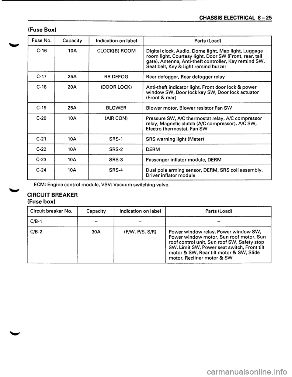
CHASSIS ELECTRICAL 8-25
(fuse Box)
Fuse No.
Capacity Indication on label Parts
(Load)
C-16
10A
CLOCK[B] ROOM Digital clock, Audio, Dome light, Map light, Luggage
room light, Courtesy light, Door SW (Front, rear, tail
gate), Antenna, Anti-theft controller, Key remind SW,
Seat belt, Key & light remind buzzer
C-17 25A RR DEFOG Rear defogger, Rear defogger relay
C-18 20A (DOOR LOCK) Anti-theft indicator light, Front door lock & power
window SW, Door lock key SW, Door lock actuator
(Front
& rear)
C-19 25A BLOWER Blower motor, Blower resistor Fan SW
C-20 10A (AIR CON) Pressure SW, A/C thermostat relay, A/C compressor
relay, Magnetic clutch
(A/C compressor), A/C SW,
Electro thermostat, Fan SW
C-21 10A SRS-1 SRS warning light (Meter)
C-22 10A SRS-2 DERM
C-23
10A SRS-3 Passenger inflator module, DERM
C-24
10A SRS-4 Dual pole arming sensor, DERM, SRS coil assembly,
Driver inflator module
ECM: Engine control module, VSV: Vacuum switching valve.
CIRCUIT BREAKER
(fuse box)
Circuit breaker No.
C/B-1
C/B-2
Capacity
-
30A
Indication on label
-
(P/W, P/S, S/R)
Parts (Load)
-
Power window relay, Power window SW,
Power window motor, Sun roof motor, Sun
roof control unit, Sun roof SW, Safety stop
SW, Limit SW, Power seat switch, Front tilt
motor & SW, Rear tilt motor & SW, Slide
motor, Recliner
motor & SW