open hood ISUZU TROOPER 1995 Workshop Manual
[x] Cancel search | Manufacturer: ISUZU, Model Year: 1995, Model line: TROOPER, Model: ISUZU TROOPER 1995Pages: 1928
Page 64 of 1928
18-10 AIR CONDITIONING
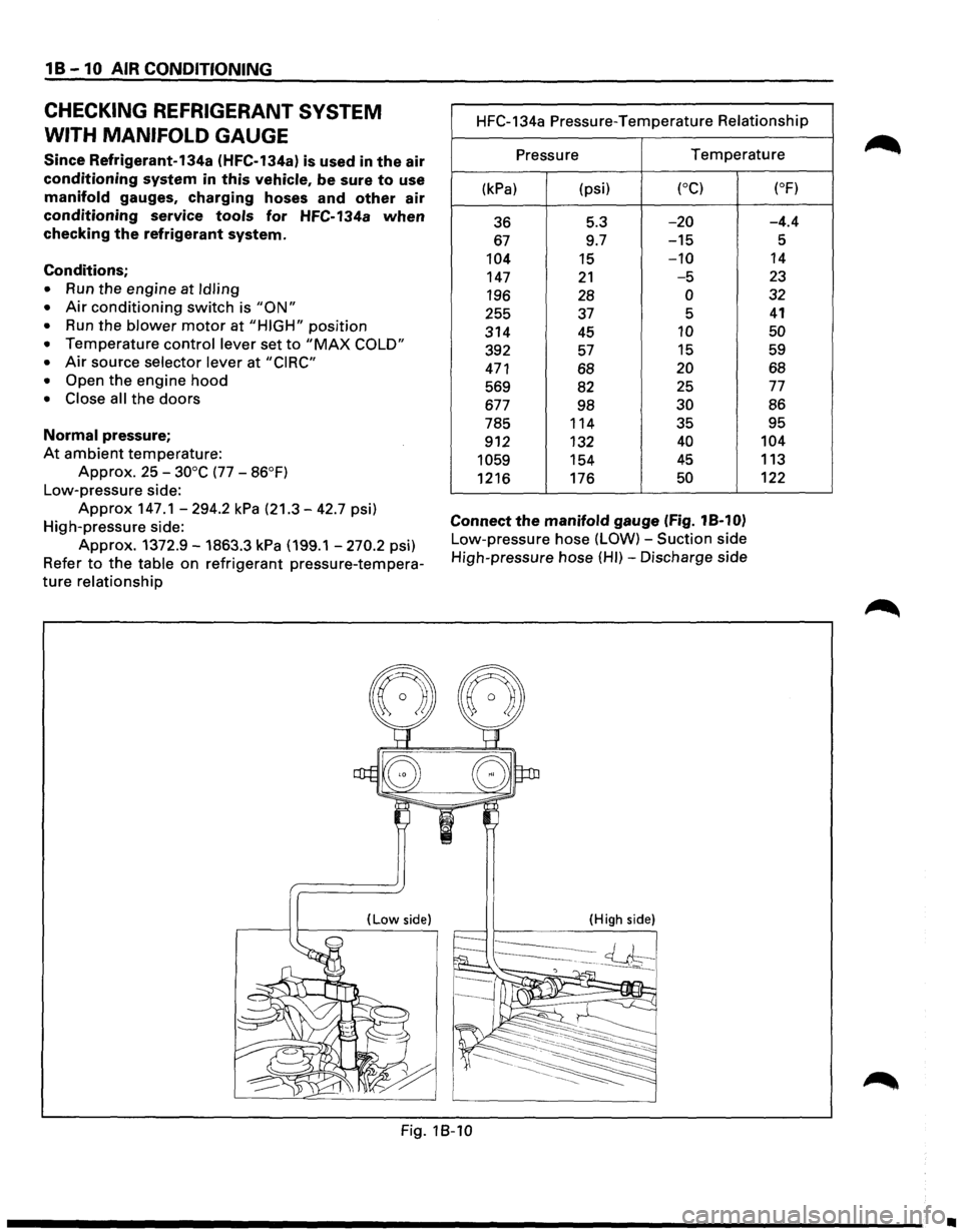
CHECKING REFRIGERANT SYSTEM
WITH MANIFOLD
GAUGE
Since Refrigerant-134a (HFC-134a) is used in the air
conditioning system in this vehicle, be sure to use
manifold gauges, charging hoses and other air
conditioning service tools for HFC-134a when
checking the refrigerant system.
Conditions;
• Run the engine at Idling
• Air conditioning switch is "ON"
• Run the blower motor at "HIGH" position
• Temperature control lever set to "MAX COLD"
•
Air source selector lever at "CIRC"
• Open
the engine hood
• Close all the doors
Normal pressure;
At ambient temperature:
Approx. 25 -30°C (77 -86°F)
Low-pressure side:
Approx 147.1-294.2 kPa (21.3-42.7 psi)
High-pressure side:
Approx. 1372.9-1863.3 kPa (199.1 -270.2 psi}
Refer
to the table on refrigerant pressure-tempera
ture relationship
(Low side)
HFC-134a Pressure-Temperature Relationship
Pressure
Temperature
(kPa) (psi) (oC)
36 5.3 -20
67 9.7 -15
104
15 -10
147 21 -5
196 28 0
255 37 5
314
45 10
392
57 15
471 68 20
569
82 25
677 98 30
785 114 35
912 132
40
1059 154 45
1216
176 50
Connect the manifold gauge (Fig. 18-10)
Low-pressure hose (LOW) -Suction side
High-pressure hose
(HI)-Discharge side
(High side)
(oF)
-4.4
5
14
23
32
41
50
59
68
77
86
95
104
113
122
Fig. 18-10
•
Page 92 of 1928
1 D-4 COMPRESSOR OVERHAUL
6. Perform oil return operation.
7. Remove the compressor and recheck the
amount of oil.
8. Adjust the compressor oil, if necessary.
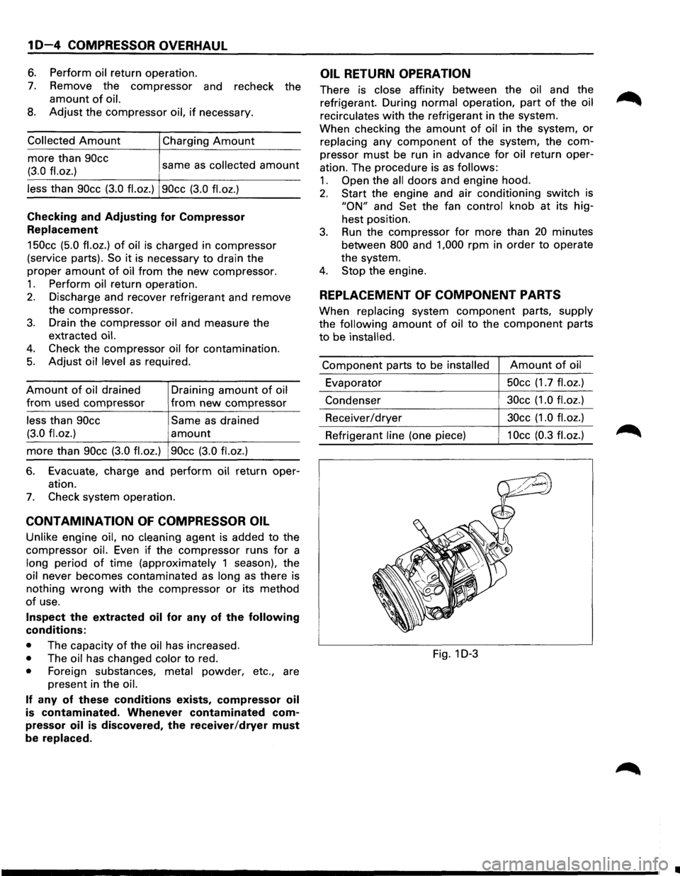
Collected Amount
more than 90cc
(3.0
fl.oz.)
Charging Amount
same as collected amount
less than 90cc (3.0 fl.oz.) 90cc (3.0 fl.oz.)
Checking and Adjusting for Compressor
Replacement
150cc (5.0 fl.oz.) of oil is charged in compressor
(service parts).
So it is necessary to drain the
proper
amount of oil from the new compressor.
1. Perform oil return operation.
2. Discharge and recover refrigerant and remove
the compressor.
3. Drain the compressor oil and measure the
extracted
oil.
4. Check the compressor oil for contamination.
5. Adjust oil level as required.
Amount of oil drained
from used compressor
less than 90cc
(3.0
fl.oz.)
Draining amount of oil
from new compressor
Same as drained
amount
more than 90cc (3.0 fl.oz.) 90cc (3.0 fl.oz.)
6. Evacuate, charge and perform oil return oper
ation.
7. Check system operation.
CONTAMINATION OF COMPRESSOR OIL
Unlike engine oil, no cleaning agent is added to the
compressor
oil. Even if the compressor runs for a
long period
of time (approximately 1 season), the
oil never becomes contaminated as long
as there is
nothing
wrong with the compressor or its method
of use.
Inspect the extracted oil for any of the following
conditions:
• The capacity of the oil has increased.
• The oil has changed color to red.
• Foreign substances, metal powder, etc., are
present in the oil.
If any of these conditions exists, compressor oil
is contaminated. Whenever contaminated com
pressor
oil is discovered, the receiver/dryer must
be
replaced.
OIL RETURN OPERATION
There is close affinity between the oil and the
refrigerant. During normal operation, part
of the oil
recirculates
with the refrigerant in the system.
When checking the
amount of oil in the system, or
replacing any component of the system, the com
pressor
must be run in advance for oil return oper
ation. The procedure is as
follows:
1. Open the all doors and engine hood.
2. Start the engine and air conditioning switch is
"ON" and Set the fan control knob at its hig
hest position.
3. Run the compressor for more than 20 minutes
between
800 and 1,000 rpm in order to operate
the system.
4. Stop the engine.
REPLACEMENT OF COMPONENT PARTS
When replacing system component parts, supply
the following
amount of oil to the component parts
to be installed.
Component parts to be installed Amount of oil
Evaporator 50cc
(1.7
fl.oz.)
Condenser 30cc
(1.0 fl.oz.)
Receiver/dryer 30cc
(1.0 fl.oz.)
Refrigerant line (one piece) 1 Occ (0.3 fl. oz.)
Fig. 1 D-3
•
Page 111 of 1928
1••1 REMOVAL (Fig. 2C-1)
Preparation: • Open the hood.
'-"' • Support the hood.
1. Front wiper arms
• Refer to "Front wiper removal" in section 8.
2. Cowl cover brackets
• Disconnect two screws each side.
3. Cowl cover
• Disconnect three screws.
4. Cowl cover seals
5. Front window lower molding
6. Cowl cover stoppers
I•• I INSTALLATION
To install, follow the removal steps in reverse order.
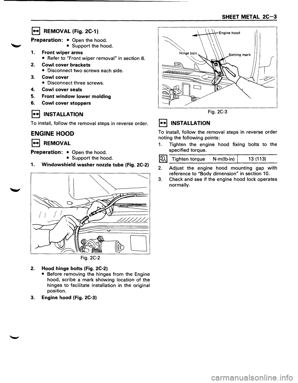
ENGINE HOOD
1••1 REMOVAL
Preparation: • Open the hood.
• Support the hood.
1. Windowshield washer nozzle tube (Fig. 2C-2)
( f
0
Fig. 2C-2
2. Hood hinge bolts (Fig. 2C-2)
• Before removing the hinges from the Engine
hood, scribe a mark showing
location of the
hinges
to facilitate installation in the original
position.
3. Engine hood (Fig. 2C-3)
SHEET METAL 2C-3
Fig. 2C-3
1••1 INSTALLATION
To install, follow the removal steps in reverse order
noting the following points:
1. Tighten the engine hood fixing bolts to the
specified torque.
1~1 Tighten torque N·m(lb·in) I 13 (113)
2. Adjust the engine hood mounting gap with
reference to "Body dimension" in section 10.
3. Check and see if the engine hood lock operates
normally.
Page 114 of 1928
2C-6 SHEET METAL
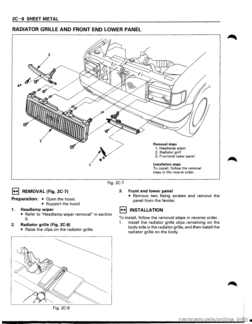
RADIATOR GRILLE AND FRONT END LOWER PANEL
3
2 Removal steps 1. Headlamp wiper
2. Radiator
grill 3. Frontend lower panel
Installation steps To install, follow the removal steps in the reverse order.
Fig. 2C-7
1••1 REMOVAL (Fig. 2C-7)
Preparation: • Open the hood.
• Support the hood.
1.
Headlamp wiper
• Refer to "Headlamp wiper removal" in section
8.
2. Radiator grille (Fig. 2C-8)
• Raise the clips on the radiator grille.
Fig. 2C-8
3. Front end lower panel
•
Remove two fixing screws and remove the
panel from the fender.
1••1 INSTALLATION
To install, follow the removal steps in reverse order.
1. Install the radiator grille clips remaining on the
body side in the radiator
grille, and then install the
radiator
grille on the body.
•
Page 116 of 1928
2C-8 SHEET METAL
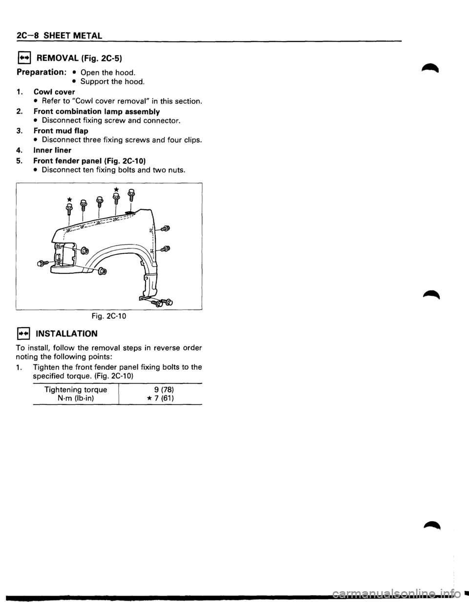
1••1 REMOVAL (Fig. 2C-5)
Preparation: • Open the hood.
• Support the hood.
1. Cowl cover
• Refer to "Cowl cover removal" in this section.
2. Front combination lamp assembly
• Disconnect fixing screw and connector.
3. Front mud flap
•
Disconnect three fixing screws and four clips.
4. Inner liner
5. Front fender panel (fig. 2C-1 0)
• Disconnect ten fixing bolts and two nuts.
Fig.
2C-10
1••1 INSTALLATION
To install, follow the removal steps in reverse order
noting the
following points:
1. Tighten the front fender panel fixing bolts to the
specified torque. (Fig.
2C-1 0)
Tightening torque
N-m (lb·in)
9 (78)
* 7 (61)
•
Page 217 of 1928
SUPPLEMENTAL RESTRAINT SYSTEM (SRS) STEERING WHEEL & COLUMN 3F4-7
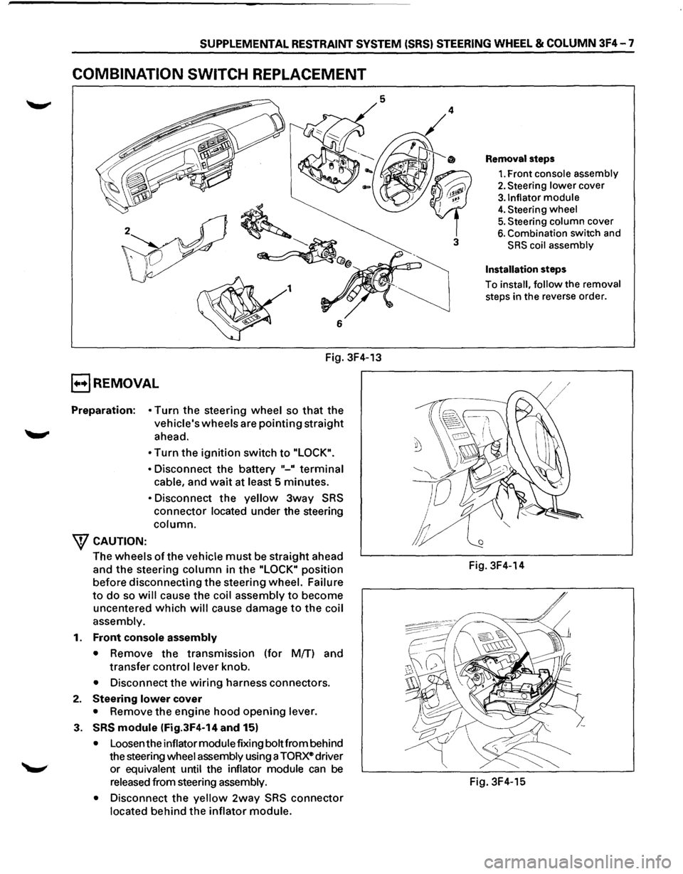
COMBINATION SWITCH REPLACEMENT
Fig. 3F4-13
E) REMOVAL
Preparation: • Turn the steering wheel so that the
vehicle's wheels are pointing straight
ahead.
W CAUTION: •
Turn the ignition switch to "LOCK".
•
Disconnect the battery "-" terminal
cable, and wait at least 5 minutes.
• Disconnect the yellow 3way SRS
connector located under the steering
column.
The wheels ofthe vehicle must be straight ahead
and
the steering column in the "LOCK" position
before disconnecting the steering wheel. Failure
to do so will cause the coil assembly to become
uncentered
which will cause damage to the coil
assembly.
1.
Front console assembly
•
Remove the transmission (for M{f) and
transfer control lever knob.
• Disconnect the wiring harness connectors.
2. Steering lower cover
• Remove the engine hood opening lever.
3. SRS module (Fig.3F4-14 and 15)
• Loosen the inflator module fixing bolt from behind
the steering
wheel assembly using a TORxe driver
or
equivalent until the inflator module can be
released from steering assembly.
•
Disconnect the yellow 2way SRS connector
located behind the inflator module.
3
Removal steps
1. Front console assembly
2. Steering lower cover
3.1nflator module
4. Steering wheel
5. Steering column cover
6. Combination switch and
SRS coil assembly
Installation steps
To install, follow the removal
steps in the reverse order.
Fig. 3F4-14
Fig. 3F4-15
Page 219 of 1928
SUPPLEMENTAL RESTRAINT SYSTEM (SRS) STEERING WHEEL & COLUMN 3F4-9
B INSTALLATION
6. Combination switch and SRS coil assembly
•
After installation of combination switch as
sembly, connect the combination switch
wiring harness connector and the SRS 3way
connector located under the steering column.
•
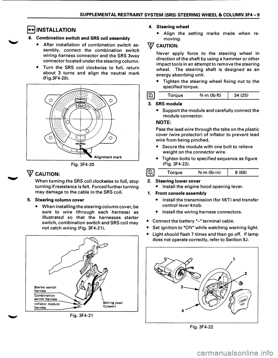
Turn the SRS coil clockwise to full, return
about 3
turns and align the neutral mark
(Fig.3F4-20).
Alignment mark
Fig. 3F4-20
WcAUTION:
When turning the SRS coil clockwise to full, stop
turning if resistance is felt. Forced further turning
may damage to the cable in the SRS coil.
5. Steering column cover
• When installing the steering column cover, be
sure
to wire (through each harness) as
illustrated so that the harnesses starter
switch,
combination switch and SRS coil may
not catch wiring (Fig. 3F4-21 ).
Starter switch
harness
Combination switch harness
Inflator module harness
Fig. 3F4-21
4. Steering wheel
• Align the setting marks made when re
moving.
W CAUTION:
Never apply force to the steering wheel in
direction
of the shaft by using a hammer or other
impact tools in an attempt to remove the steering
wheel. The steering shaft is designed as an
energy absorbing unit.
• Tighten the steering wheel fixing nut to the
specified torque.
Torque
N·m (lb-ft) 34 (25)
3. SRS module
• Support the module and carefully connect the
module connector.
NOTE:
Pass the lead wire through the tabs on the plastic
cover (wire protector) of inflator to prevent lead
wire from being pinched.
• Secure the module with one bolt to relieve
weight on the connector wire.
• Tighten bolts to specified sequence as figure
(Fig. 3F4-22).
Torque
N·m (lb·in) 8 (69)
2. Steering lower cover
• Install the engine hood opening lever.
1. Front console assembly
• Install
the transmission (for MfT) and transfer
control lever knob.
• Install the wiring harness connectors.
• Connect the battery "-"terminal cable.
• Set
ignition to ·oN" while watching warning light.
•
Light should flash 7 times and then go off. If lamp
does not operate correctly, refer to Section 9J.
Fig. 3F4-22
Page 220 of 1928
3F4-10 SUPPLEMENTAL RESTRAINT SYSTEM (SRS) STEERING WHEEL & COLUMN
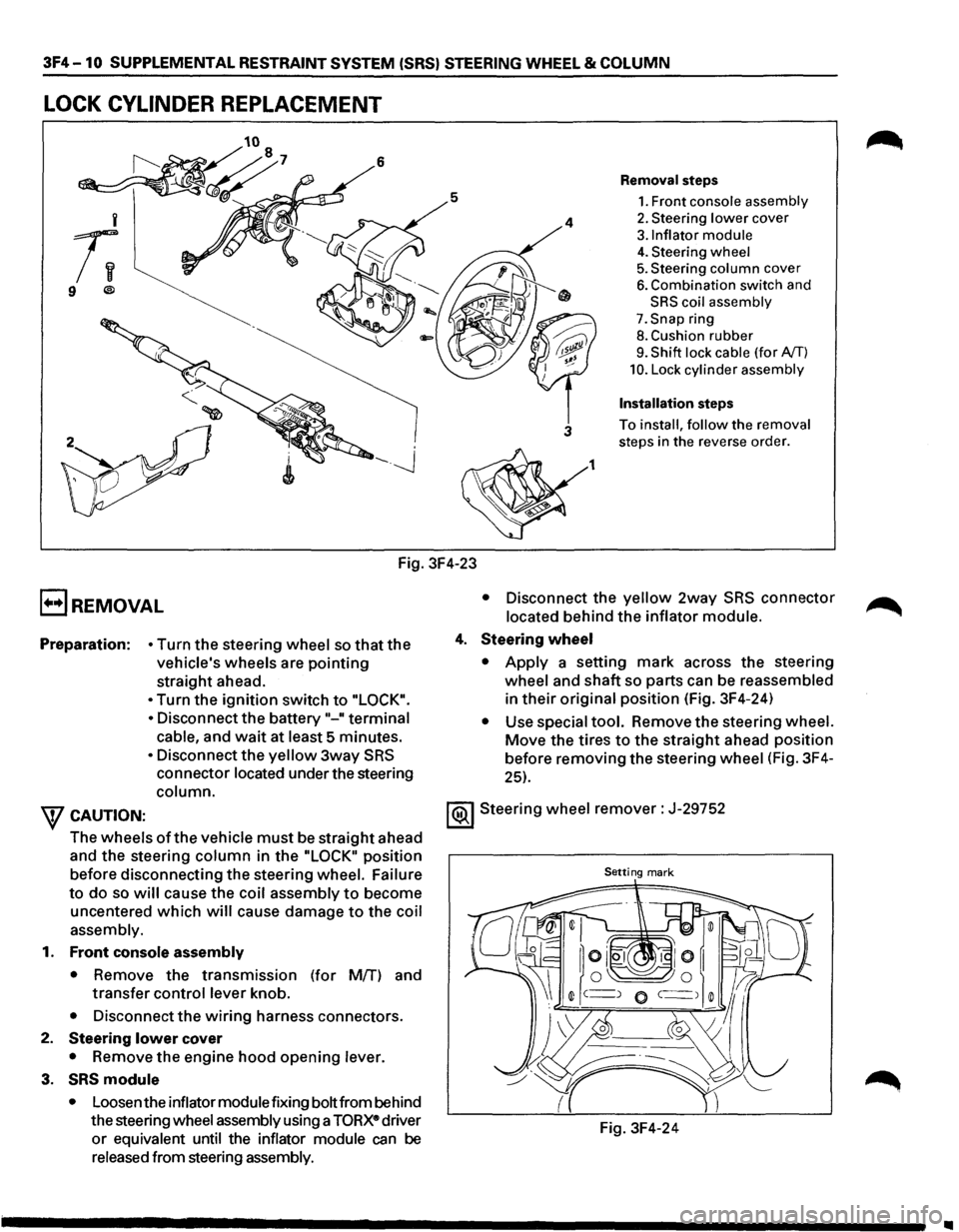
LOCK CYLINDER REPLACEMENT
5
i
;;
9 ®
Fig. 3F4-23
E) REMOVAL
4
3
1
Removal steps
1. Front console assembly
2. Steering lower cover
3.1nflator module
4. Steering wheel
5. Steering column cover
6. Combination switch and
SRS coil assembly
7. Snap ring
8. Cushion rubber
9. Shift lock cable (for AfT)
10. Lock cylinder assembly
Installation steps
To install, follow the removal
steps in the reverse order.
• Disconnect the yellow 2way SRS connector
located behind the inflator module.
Preparation:
• Turn the steering wheel so that the
vehicle's wheels are
pointing
straight ahead.
4. Steering wheel
• Turn the ignition switch to "LOCK".
•
Disconnect the battery"-" terminal
cable, and wait at least 5 minutes.
• Disconnect the yellow 3way SRS
connector located under the steering
column.
• Apply a setting mark across the steering
wheel and
shaft so parts can be reassembled
in
their original position (Fig. 3F4-24)
• Use special tool. Remove the steering wheel.
Move the tires to the straight ahead position
before removing the steering wheel (Fig. 3F4-
25).
W CAUTION: 1®.1 Steering wheel remover: J-29752
The wheels
of the vehicle must be straight ahead
and the steering
column in the "LOCK" position
before disconnecting the steering wheel. Failure
Setting mark
to do so will cause the coil assembly to become
uncentered
which will cause damage to the coil
assembly.
1.
Front console assembly
• Remove the transmission (for Mff) and
transfer
control lever knob.
• Disconnect the wiring harness connectors.
2. Steering lower cover
• Remove the engine hood opening lever.
3. SRS module
• Loosen the inflator module fixing bolt from behind
the steering wheel assembly using a
TORXe driver
or equivalent until the inflator module can be
released from steering assembly. Fig.
3F4-24
•
Page 222 of 1928
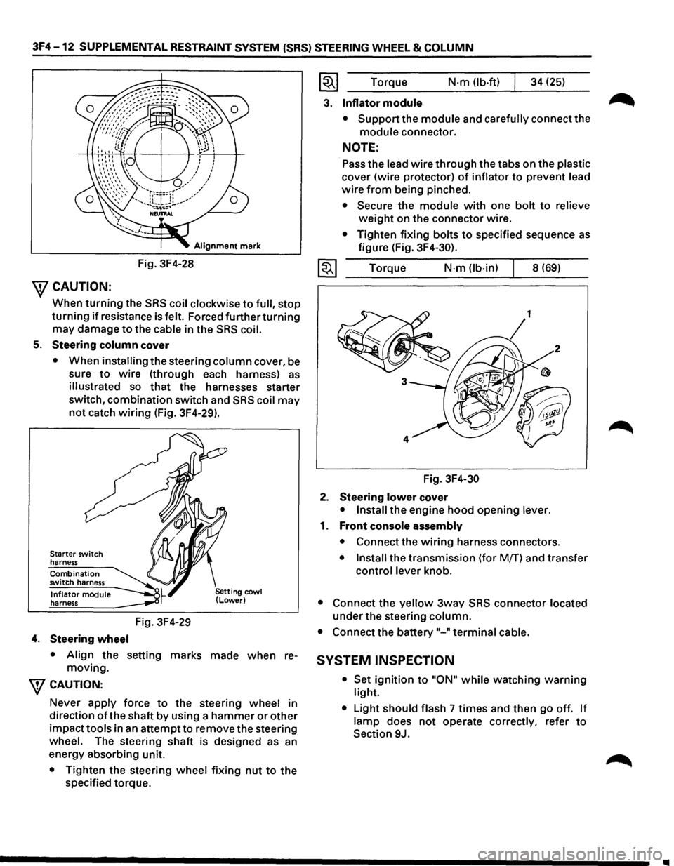
3F4 -12 SUPPLEMENTAL RESTRAINT SYSTEM (SRS) STEERING WHEEL & COLUMN
Alignment mark
Fig. 3F4-28
\fCAUTION:
When turning the SRS coil clockwise to full, stop
turning if resistance is felt. Forced further turning
may damage to the cable in the SRS coil.
5. Steering column cover
• When installing the steering column cover, be
sure
to wire (through each harness) as
illustrated so that the harnesses starter
switch,
combination switch and SRS coil may
not catch wiring (Fig. 3F4-29).
Starter switch
harness
Combination
switch harness
Inflator module
harness
4. Steering wheel
Fig. 3F4-29
• Align the setting marks made when re
moving.
\fCAUTION:
Never apply force to the steering wheel in
direction
of the shaft by using a hammer or other
impacttools in an attemptto remove the steering
wheel. The steering shaft is designed as an
energy absorbing unit.
• Tighten the steering wheel fixing nut to the
specified torque.
~~~ Torque N·m (lb-ft) 34 (25)
3. Inflator module
• Support the module and carefully connect the
module connector.
NOTE:
Pass the lead wire through the tabs on the plastic
cover (wire protector) of inflator to prevent lead
wire from being pinched.
• Secure the module with one bolt to relieve
weight on the connector wire.
• Tighten fixing bolts to specified sequence as
figure (Fig. 3F4-30).
1~1 Torque N·m (lb-in) 8 (69)
Fig.
3F4-30
2. Steering lower cover
• Install the engine hood opening lever.
1. Front console assembly
• Connect the wiring harness connectors.
• Install the transmission (for Mff) and transfer
control lever knob.
• Connect the yellow 3way SRS connector located
under the steering column.
• Connect the battery"-" terminal cable.
SYSTEM INSPECTION
• Set ignition to "ON" while watching warning
light.
•
Light should flash 7 times and then go off. If
lamp does not operate correctly, refer to
Section 9J.
Page 224 of 1928
3F4-14 SUPPLEMENTAL RESTRAINT SYSTEM (SRS) STEERING WHEEL & COLUMN
EJREMOVAL
Preparation: • Turn the steering wheel so that the
vehicle's
wheels are pointing straight
ahead.
• Turn the ignition switch to "LOCK".
•
Disconnect the battery "-" terminal
cable,
and wait at least 5 minutes.
• Disconnect the yellow 3way SRS
connector located under the steering
column.
wcAUTION:
The wheel of the vehicle must be straight ahead
and the steering
column in the "LOCK• position
before disconnecting the steering
column from
the steering gear.
Failure to do so will cause the SRS coil assembly
to become uncentered which will cause damage
to the SRS coil assembly.
1. Front console assembly
• Disconnect the transmission (for MfT) and
transfer
control lever knob.
• Disconnect the wiring harness connectors.
2. Steering lower cover
• Remove the engine hood opening lever.
3. Driver knee bolster (reinforcement)
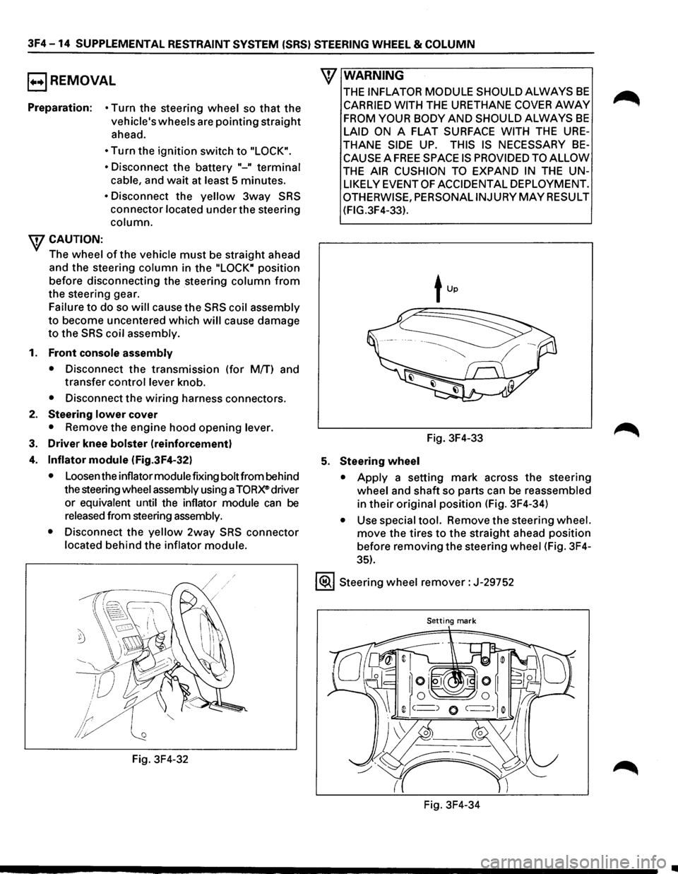
4. Inflator module (Fig.3F4-32)
• Loosen the inflator module fixing bolt from behind
the steering
wheel assembly using a TORX® driver
or
equivalent until the inflator module can be
released from steering assembly.
•
Disconnect the yellow 2way SRS connector
located behind the inflator module.
Fig. 3F4-32
\V WARNING
THE INFLATOR MODULE SHOULD ALWAYS BE
CARRIED WITH THE URETHANE COVER AWAY
FROM YOUR BODY AND SHOULD ALWAYS BE
LAID ON A FLAT SURFACE WITH THE URE
THANE SIDE UP. THIS IS NECESSARY BE
CAUSE A FREE SPACE IS PROVIDED TO ALLOW
THE AIR CUSHION TO EXPAND IN THE UN
LIKELY EVENT OF ACCIDENTAL DEPLOYMENT.
OTHERWISE, PERSONALINJURYMAYRESULT
(FIG.3F4-33).
Fig. 3F4-33
5. Steering wheel
• Apply a setting mark across the steering
wheel and shaft so parts can be reassembled
in their original position (Fig. 3F4-34)
• Use special tool. Remove the steering wheel.
move the tires to the straight ahead position
before removing the steering
wheel (Fig. 3F4-
35).
1®.1 Steering wheel remover: J-29752
Setting mark
Fig. 3F4-34
..