gas type ISUZU TROOPER 1995 Workshop Manual
[x] Cancel search | Manufacturer: ISUZU, Model Year: 1995, Model line: TROOPER, Model: ISUZU TROOPER 1995Pages: 1928
Page 8 of 1928
OA-4 GENERAL INFORMATION
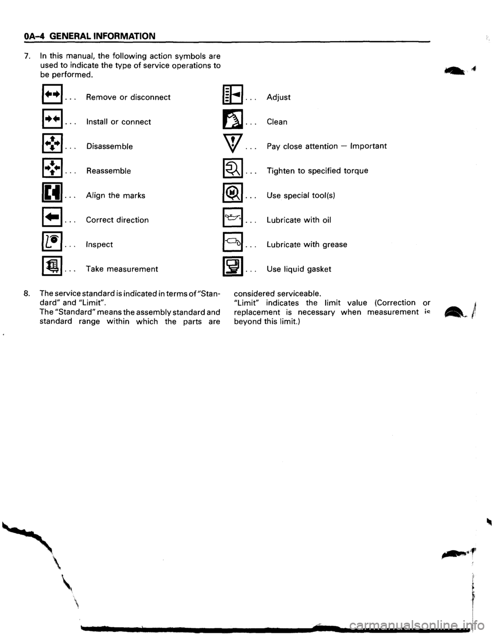
7. In this manual, the following action symbols are
used
to indicate the type of service operations to
be performed.
a ... Remove or disconnect
E) ... Install or connect
1•!•1 ... Disassemble
l•!•l ... Reassemble
(Et ... Align the marks
~ ... Correct direction
~ ... Inspect
[j) ... Take measurement
8. The service standard is indicated in terms of"Stan
dard" and "Limit".
The "Standard" means the assembly standard and
standard range
within which the parts are
[E ... Adjust
fll ... Clean
w ... Pay close attention -Important
~ ... Tighten to specified torque
~ ... Use special tool(s)
E) ... Lubricate with oil
§] ... Lubricate with grease
~ ... Use liquid gasket
considered serviceable.
"Limit" indicates the limit value (Correction or
replacement is necessary when measurement ic:
beyond this limit.)
.. ,f•
Page 9 of 1928
IDENTIFICATION
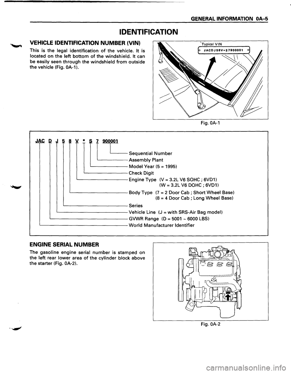
VEHICLE IDENTIFICATION NUMBER (VIN)
This is the legal identification of the vehicle. It is
located
on the left bottom of the windshield. It can
be easily seen
through the windshield from outside
the vehicle (Fig.
OA-1).
~ !~ :i ~ v * ~7L_
~Sequential Number
Assembly Plant
Model Year (5 = 1995)
Check Digit
GENERAL INFORMATION OA-5
Fig. OA-1
Engine Type (V = 3.2L V6 SOHC ; 6VD1)
(W = 3.2L V6
DOHC ; 6VD1)
Body Type
(7 = 2 Door Cab ; Short Wheel Base)
(8 = 4 Door Cab ; Long Wheel Base)
Series
Vehicle Line
(J =with SRS-Air Bag model)
GVWR Range
(0 = 5001 -6000 LBS)
World Manufacturer Identifier
ENGINE SERIAL NUMBER
The gasoline engine serial number is stamped on
the
left rear lower area of the cylinder block above
the starter (Fig. OA-2).
Fig. OA-2
Page 21 of 1928
FLUID LEVEL CHECK
A fluid loss in any system (except windshield
washer) may indicate a problem. Repair the system
at once.
Engine
oil level -Check level and add if
necessary. The best time to check the engine oil
level is
when the oil is warm. After stopping the
engine with the vehicle on a level surface, wait a
few minutes for the oil to drain back to the oil pan.
Pull
out the oil level indicator (dipstick). Wipe it
clean and push the oil level indicator back down all
the
way. Pull out the oil level indicator, keeping the
tip down, and look at the oil level on it.
Add oil, if needed, to keep the oil level above
the
"ADD" mark and between the "ADD" and
"FULL" marks in the operating range area. Avoid
overfilling the engine since this may cause engine
damage. Push
the oil level indicator back down all
the
way after taking the reading.
If you check the oil level when the oil is cold, do
not run the engine first. The cold oil will not drain
back
to the pan fast enough to give a true oil level.
Engine coolant level and condition -Check
engine coolant level in the coolant reservoir and
add engine
coolant if necessary. Inspect the engine
coolant and replace it if dirty or rusty.
Windshield washer fluid level -Check washer
fluid level in reservoir and add if necessary.
Power steering system reservoir level-Check
and keep at
proper level.
Brake master cylinder reservoir level -Check
fluid. Keep fluid at proper level. A low fluid level
can indicate
worn disc brake pads which may need
to be serviced.
Hydraulic clutch system -Check fluid l~vel in
the reservoir.
Add fluid as required.
Battery fluid level -Check fluid level in the
battery.
FLUID LEAK CHECK
Check for fuel, water, oil or other fluid leaks by
looking at the surface beneath the vehicle after it
has been parked for a while. Water dripping from
the air conditioning system after use is normal. If
you notice gasoline fumes or fluid at any time,
locate the source and correct it at once.
ENGINE OIL AND OIL FILTER
REPLACEMENT
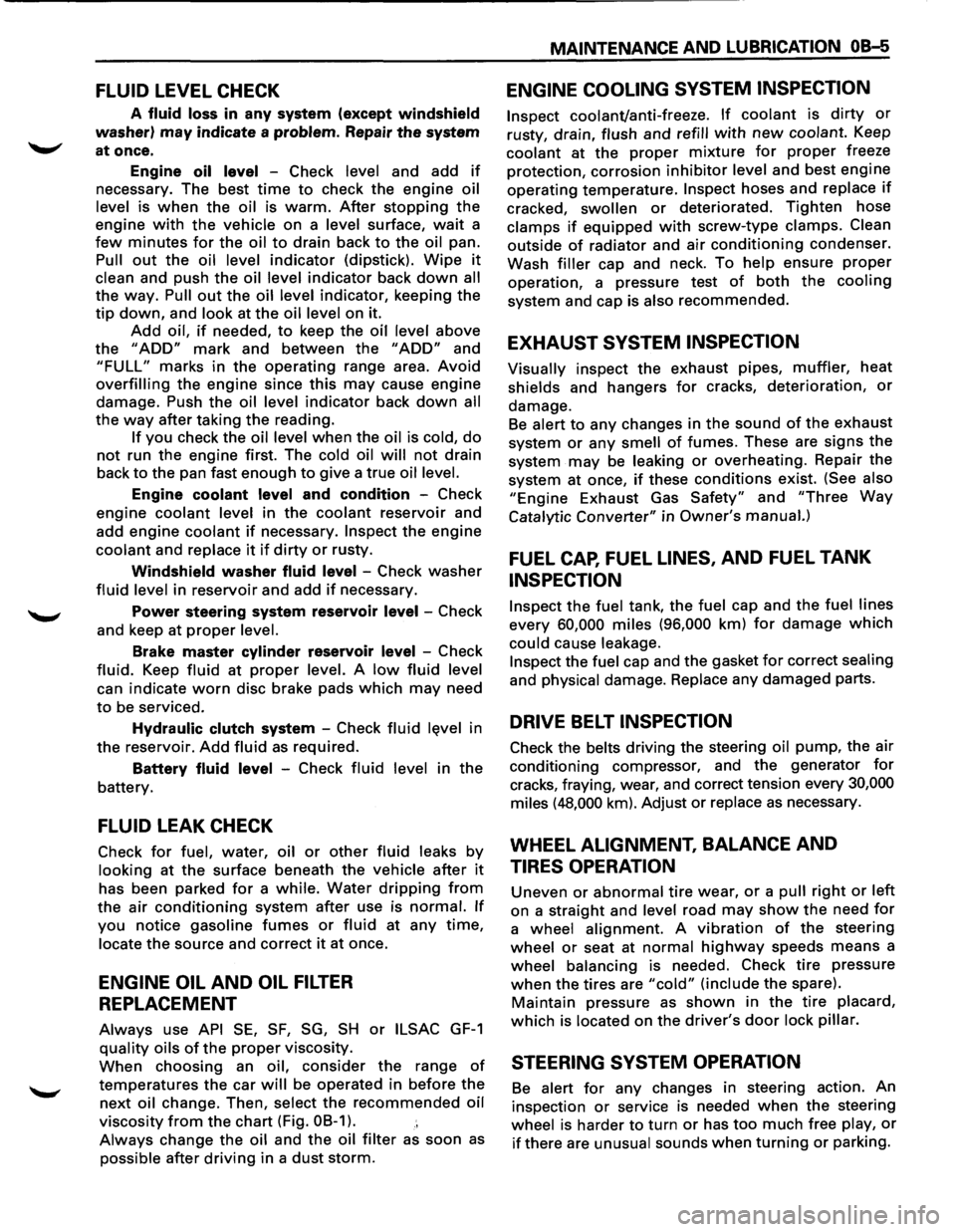
Always use API SE, SF, SG, SH or ILSAC GF-1
quality oils of the proper viscosity.
When choosing an oil, consider the range of
temperatures the car will be operated in before the
next oil change. Then, select the recommended oil
viscosity
from the chart (Fig. OB-1).
Always change the oil and the oil filter as soon as
possible after driving in a dust storm.
MAINTENANCE AND LUBRICATION OB-5
ENGINE COOLING SYSTEM INSPECTION
Inspect coolant/anti-freeze. If coolant is dirty or
rusty, drain, flush and refill with new coolant. Keep
coolant at the proper mixture for proper freeze
protection,
corrosion inhibitor level and best engine
operating temperature.
Inspect hoses and replace if
cracked, swollen or deteriorated. Tighten hose
clamps if equipped with screw-type clamps. Clean
outside of radiator and air conditioning condenser.
Wash
filler cap and neck. To help ensure proper
operation, a pressure test of both the cooling
system and cap is also recommended.
EXHAUST SYSTEM INSPECTION
Visually inspect the exhaust pipes, muffler, heat
shields and hangers
for cracks, deterioration, or
damage.
Be alert to any changes in the sound of the exhaust
system
or any smell of fumes. These are signs the
system may be leaking or overheating. Repair the
system at once,
if these conditions exist. (See also
"Engine Exhaust Gas Safety" and "Three Way
Catalytic Converter" in Owner's manual.)
FUEL CAP, FUEL LINES, AND FUEL TANK
INSPECTION
Inspect the fuel tank, the fuel cap and the fuel lines
every
60,000 miles (96,000 km) for damage which
could cause leakage.
Inspect the fuel cap and the gasket for correct sealing
and physical damage. Replace any damaged parts.
DRIVE BELT INSPECTION
Check the belts driving the steering oil pump, the air
conditioning compressor, and the generator
for
cracks, fraying, wear, and correct tension every 30,000
miles (48,000 km). Adjust or replace as necessary.
WHEEL ALIGNMENT, BALANCE AND
TIRES OPERATION
Uneven or abnormal tire wear, or a pull right or left
on a straight and level road may show the need for
a wheel alignment. A vibration of the steering
wheel or seat at normal highway speeds means a
wheel balancing is needed. Check tire pressure
when the tires are "cold" (include the spare).
Maintain pressure as shown in the tire placard,
which is located on the driver's door lock pillar.
STEERING SYSTEM OPERATION
Be alert for any changes in steering action. An
inspection
or service is needed when the steering
wheel is harder
to turn or has too much free play, or
if there are unusual sounds when turning or parking.
Page 27 of 1928
,
MAINTENANCE AND LUBRICATION OB-11
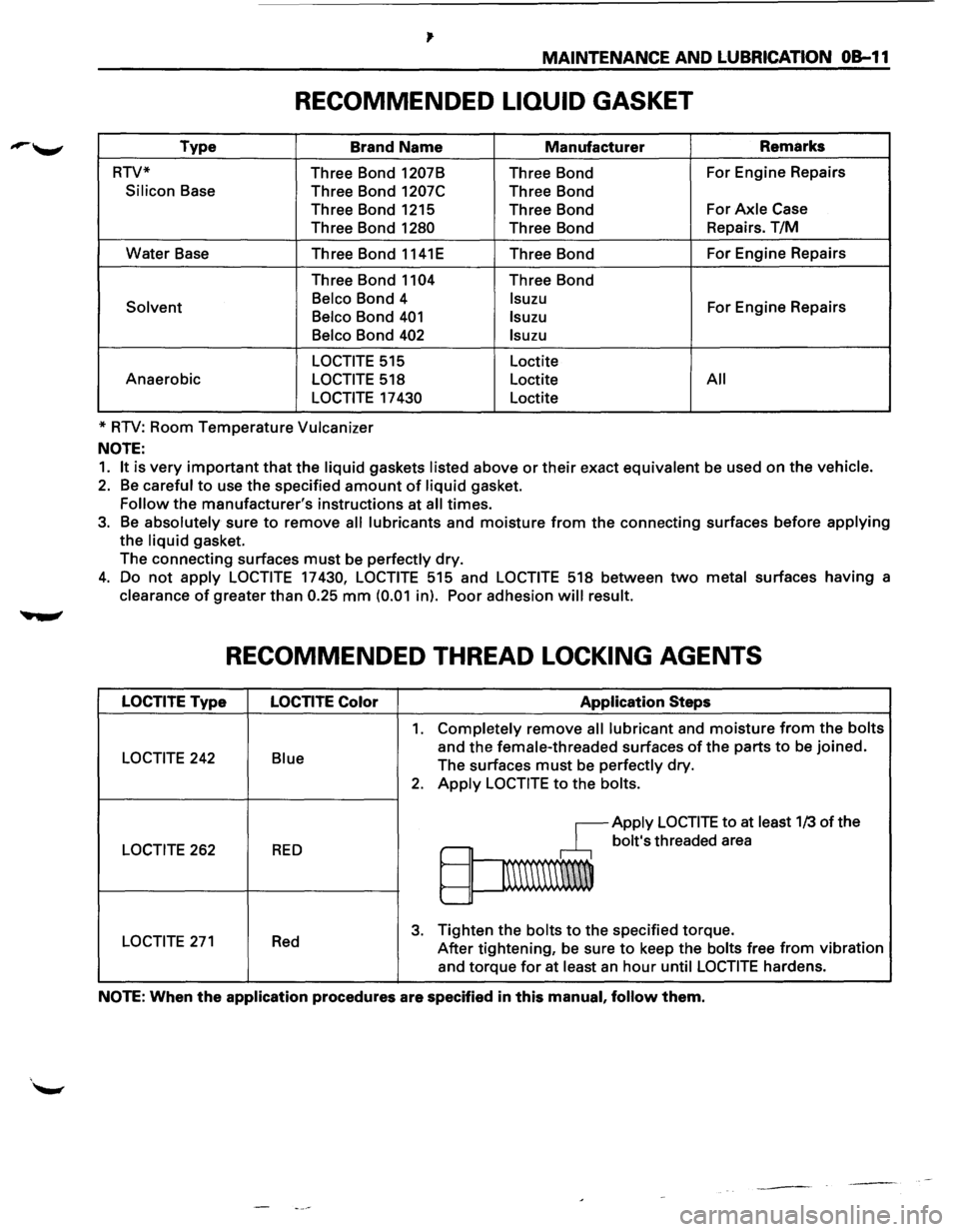
RECOMMENDED LIQUID GASKET
Type Brand Name Manufacturer Remarks
RTV* Three Bond
1207B Three Bond For
Engine Repairs
Silicon Base
Three Bond 1207C Three Bond
Three Bond 1215 Three Bond For
Axle Case
Three Bond
1280 Three Bond Repairs.
T/M
Water Base
Three Bond 1141E Three Bond For
Engine Repairs
Three Bond
1104 Three Bond
Solvent Belco Bond
4 lsuzu For Engine Repairs Belco Bond 401 lsuzu
Belco
Bond 402 lsuzu
LOCTITE
515 Loctite
Anaerobic
LOCTITE 518 Loctite All
LOCTITE
17 430 Loctite
*
RTV: Room Temperature Vulcanizer
NOTE:
1. It is very important that the liquid gaskets listed above or their exact equivalent be used on the vehicle.
2. Be careful to use the specified amount of liquid gasket.
Follow the manufacturer's instructions at all times.
3. Be absolutely sure to remove all lubricants and moisture from the connecting surfaces before applying
the liquid gasket.
The connecting surfaces
must be perfectly dry.
4. Do not apply LOCTITE 17430, LOCTITE 515 and LOCTITE 518 between two metal surfaces having a
clearance
of greater than 0.25 mm (0.01 in). Poor adhesion will result.
RECOMMENDED THREAD LOCKING AGENTS
LOCTITE Type LOCTITE Color Application Steps
1. Completely remove all lubricant and moisture from the bolts
LOCTITE 242 Blue and the female-threaded surfaces of the parts to be joined.
The surfaces
must be perfectly dry.
2. Apply LOCTITE to the bolts.
~Apply LOCTITE to at least 1/3 of the
LOCTITE 262 RED ,.-bolt's threaded area
~
1\\\\\\\W
'--
LOCTITE 271 Red 3. Tighten the bolts to the specified torque.
After tightening, be sure
to keep the bolts free from vibration
and torque
for at least an hour until LOCTITE hardens.
NOTE: When the application procedures are specified in this manual, follow them.
Page 57 of 1928
The refrigeration cycle includes the following four
processes as the refrigerant changes repeatedly
from liquid to gas and back to liquid while circulat
ing.
EVAPORATION
The refrigerant is changed from a liquid to a gas in
side
the evaporator. The refrigerant mist that enters
the evaporator vaporizes readily. The liquid refrige
rant removes
the required quantity of heat (latent
heat of vaporization) from the air around the evap
orator core cooling fins and rapidly vaporizes.
Removing the heat cools the air, which is then
radiated
from the fins and lowers the temperature of
the air inside the vehicle.
The refrigerant liquid sent from the expansion valve
and the vaporized refrigerant gas are both present
inside the
evaporator and the liquid is converted to
gas.
With this change from liquid to gas, the pressure
inside
the evaporator must be kept low enough for
vaporization to occur at a lower temperature.
Because of that, the vaporized refrigerant is sucked
into the compressor.
COMPRESSION
The refrigerant is compressed by the compressor
until it is easily liquefied at normal temperature.
The vaporized
refrigerant in the evaporator is sucked
into the compressor. This action maintains the
refrigerant inside the evaporator at a low pressure
so
that it can easily vaporize, even at low tempera
tures close to ooc (32°F).
Also, the refrigerant sucked into the compressor is
compressed inside the
cylinder to increase the
pressure and temperature to values such that the
refrigerant can easily liquefy at normal ambient
temperatures.
CONDENSATION
The refrigerant inside the condenser is cooled by the
outside air and changes from gas to liquid.
The high temperature, high pressure gas coming
from the compressor is cooled and liquefied by the
condenser with outside air and accumulated in the
receiver/drier. The heat radiated to the outside air by
the high temperature, high pressure gas in the
compressor is called heat of condensation. This is
the total quantity of heat (heat of vaporization) the
refrigerant removes
from the vehicle interior via the
evaporator and the work (calculated as the quantity
of heat) performed for compression.
'-' EXPANSION
The expansion valve lowers the pressure of the
refrigerant liquid so that it can easily vaporize.
AIR CONDITIONING 1 B -3
The process of lowering the pressure to encourage
vaporization before the
liquefied refrigerant is sent
to the evaporator is called expansion. In addition,
the expansion valve controls the flow rate of the
refrigerant liquid while decreasing the pressure.
That is, the quantity of refrigerant liquid vaporized
inside
the evaporator is determined by the quantity
of heat which must be removed at a prescribed
vaporization temperature.
It is important that the
quantity of refrigerant be controlled to exactly the
right value.
COMPRESSOR
It compressor performs two main functions:
It compresses low-pressure and low-temperature
refrigerant vapor from the evaporator into high
pressure and high-temperature
refrigerant vapor to
the condenser. And it pumps refrigerant and
refrigerant
oil through the air conditioning system.
This vehicle is equipped with five-vane rotary com
pressor.
The
thermo sensor is installed to the front head of
the compressor to protect it by stopping its
operation when the refrigerant gas is insufficient or
when the temperature is abnormally high.
• OFF ...... 160 ±soc (320.0 ± 9.0°F)
• ON
...... 135 ±soc (27S.O ± 9.0°F)
The specified amount of the compressor oil is 1SOcc
(S.O fl.oz.).
The oil used in the HFC-134a system compressor
differs from that used in R-12 systems.
Also, compressor oil to be used varies according to
the compressor model. Be sure to avoid mixing two
or more different types of oil.
If the wrong oil is used, lubrication will be poor and
the compressor will seize or malfunction.
The magnetic clutch connector is a waterproof
type.
MAGNETIC CLUTCH
The compressor is driven by the drive belt from the
crank
pulley of the engine. If the compressor is ac
tivated each
time the engine is started, this causes
too much load to the engine. The magnetic clutch
transmits the power from the engine to the com
pressor and activates it when the air conditioning is
"ON". Also, it cuts off the power from the engine to
the compressor when the air conditioning is "OFF".
(Magnetic clutch repair procedure can be found in
Section 1 D.)
Page 58 of 1928
1 B - 4 AIR CONDITIONING
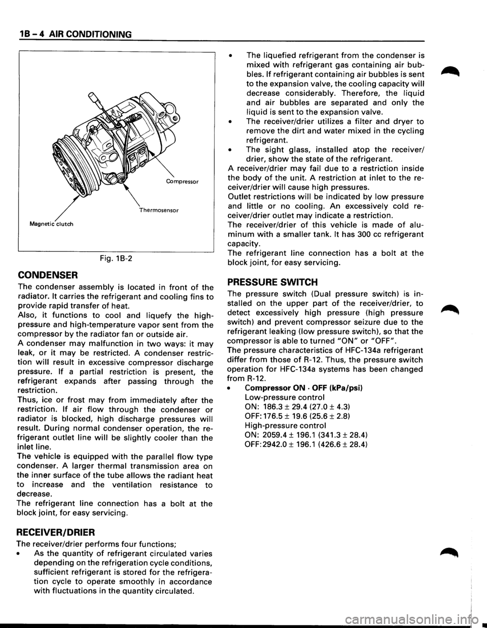
Compressor
Thermosensor
Magnetic clutch
Fig. 18-2
CONDENSER
The condenser assembly is located in front of the
radiator. It carries the refrigerant and cooling fins to
provide rapid transfer of heat.
Also, it functions to cool and liquefy the high
pressure and high-temperature vapor sent from the
compressor by the radiator fan or outside air.
A condenser
may malfunction in two ways: it may
leak, or it may be restricted. A condenser restric
tion will result in excessive compressor discharge
pressure.
If a partial restriction is present, the
refrigerant expands after passing through the
restriction.
Thus, ice
or frost may from immediately after the
restriction. If air flow through the condenser or
radiator is blocked, high discharge pressures will
result. During normal condenser operation, the re
frigerant outlet line will be slightly cooler than the
inlet line.
The vehicle is equipped with the parallel flow type
condenser. A larger thermal transmission area on
the inner surface of the tube allows the radiant heat
to increase and the ventilation resistance to
decrease.
The
refrigerant line connection has a bolt at the
block joint, for easy servicing.
RECEIVER/DRIER
The receiver/drier performs four functions;
• As the quantity of refrigerant circulated varies
depending on the refrigeration cycle conditions,
sufficient refrigerant is stored for the refrigera
tion cycle to operate smoothly in accordance
with fluctuations in the quantity circulated. •
The liquefied refrigerant from the condenser
is
mixed with refrigerant gas containing air bub
bles. If refrigerant containing air bubbles is sent
to the expansion valve, the cooling capacity will
decrease considerably. Therefore, the liquid
and air bubbles are separated and only the
liquid is sent to the expansion valve.
•
The receiver/drier utilizes a filter and dryer to
remove the dirt and water mixed in the cycling
refrigerant.
• The sight glass, installed atop the receiver/
drier, show the state of the refrigerant.
A receiver/drier may fail due to a restriction inside
the body of the unit. A restriction at inlet to the re
ceiver/drier
will cause high pressures.
Outlet restrictions will be indicated by low pressure
and
little or no cooling. An excessively cold re
ceiver/drier
outlet may indicate a restriction.
The receiver/drier
of this vehicle is made of alu
minum with a smaller tank. It has 300 cc refrigerant
capacity.
The
refrigerant line connection has a bolt at the
block joint, for easy servicing.
PRESSURE SWITCH
The pressure switch (Dual pressure switch) is in
stalled on the upper part of the receiver/drier, to
detect excessively high pressure (high pressure
switch) and prevent compressor seizure due to the
refrigerant leaking (low pressure switch), so that the
compressor is able to turned "ON" or "OFF".
The pressure characteristics of HFC-134a refrigerant
differ from those of R-12. Thus, the pressure switch
operation for HFC-134a systems has been changed
from R-12.
• Compressor ON · OFF (kPa/psi)
Low-pressure control
ON: 186.3 ± 29.4 (27.0 ± 4.3)
OFF: 176.5 ± 19.6 (25.6 ± 2.8)
High-pressure
control
ON: 2059.4 ± 196.1 (341.3 ± 28.4)
OFF: 2942.0 ± 196.1 (426.6 ± 28.4)
Page 89 of 1928
COMPRESSOR OVERHAUL 1 D - 1
SECTION 10
COMPRESSOR OVERHAUL
CONTENTS
General Description . . . . . . . . . . . . . . . . . . . . . 1 D-1
Diagnosis . . . . . . . . . . . . . . . . . . . . . . . . . . . . . 1
D-2
General Information . . . . . . . . . . . . . . . . . . . . 1 D-3
Compressor Oil . . . . . . . . . . . . . . . . . . . . . . 1 D-3
Service Procedures . . . . . . . . . . . . . . . . . . . . . 1D-5
Magnetic Clutch Assembly . . . . . . . . . . . . . 1 D-5
Main Data and Specifications . . . . . . . . . . . . . 1 D-8
General Specifications . . . . . . . . . . . . . . . . . 1 D-8
Torque Specifications . . . . . . . . . . . . . . . . . 1 D-8
Special Tools . . . . . . . . . . . . . . . . . . . . . . . . . . 1D-9
GENERAL DESCRIPTION
When servicing the compressor, keep dirt or foreign
material from getting on or into the compressor
parts and system. Clean tools and a clean work area
are
important for proper service. The compressor
connections and the outside of the compressor
should be cleaned before any "On-Vehicle" repair,
or before removal of the compressor. The parts must
be kept clean at all times and any parts to be
reassembled
should be cleaned with Trichloro
ethane, naphtha, kerosene, or equivalent solvent,
and
dried with dry air. Use only lint free cloths to
wipe parts.
The
operations described below are based on bench
overhaul
with compressor removed from the
vehicle, except as noted. They have been prepared
in
order of accessibility of the components. When
the compressor is removed from the vehicle for
servicing, the oil remaining in the compressor
should be discarded and new compressor oil added
to the compressor.
Magnetic clutch assembly repair procedures require
that the system be discharged of refrigerant. (Refer
to Section 1 B for "REFRIGERANT RECOVERY".)
Compressor malfunction will appear in one of four
ways: noise, seizure, leakage or low discharge
pressure. Resonant
compressor noises are not
cause for alarm; however, irregular noise or rattles
may indicate broken parts or excessive clearances
due to wear. To check seizure, de-energize the
magnetic clutch and check to see if the drive plate
can be rotated.
If rotation is impossible, the com
pressor is seized. Low discharge pressure may be
due to a faulty internal seal of the compressor, or a
restriction in the compressor.
Low discharge pres
sure
may also be due to an insufficient refrigerant
charge
or a restriction elsewhere in the system.
These possibilities
should be checked prior to
servicing the compressor. If the compressor is
inoperative,
but is not seized, check to see if current
is being supplied to the magnetic clutch coil
terminals.
This vehicle is equipped with five-vane rotary com
pressor.
The
compressor has vanes built into a rotor which is
mounted on a shaft.
When the shaft rotates, the vanes built into the
cylinder block assembly are opened by centrifugal
force.
This changes the volume of the space formed by the
rotor and cylinder, resulting in the intake and
compression of the refrigerant gas. The discharge
valve and the
valve stopper, which protects the
discharge valve, are
built into the cylinder block
assembly. There is no suction valve but a shaft seal
is
installed between the shaft and head; a trigger
valve, which applies back pressure to the vanes, is
installed in the cylinder block and a refrigerant gas
temperature sensor is installed in the front head.
The specified
quantity of compressor oil is contained
in
the compressor to lubricate the various parts
using
the refrigerant gas discharge pressure.
The thermo sensor is installed to the front head of
the compressor to protect it by stopping its
operation when the refrigerant gas is insufficient or
when the temperature get abnormally high.
•OFF ..... 160 ±soc (320.0 ± 9.0°F)
•ON ..... 135 ±soc (275.0 ± 9.0°F)
The oil used in the HFC-134a system compressor
differs from that used in R-12 systems.
Also, compressor
oil to be used varies according to
the compressor model. Be sure to avoid mixing two
or more different types of oil.
If the wrong oil is used, lubrication will be poor and
the compressor will seize or malfunction.
The specified
amount of the compressor oil is
150cc (5.0 fl.oz.).
Page 91 of 1928
COMPRESSOR OVERHAUL 10-3
GENERAL INFORMATION
COMPRESSOR OIL
OIL SPECIFICATION
• The HFC-134a system requires a synthetic
(PAG) compressor oil whereas the R-12 system
requires a
mineral compressor oil. The two oils
must never be mixed.
• Compressor (PAG) oil varies according to com
pressor model. Be sure to use oil specified for
the model of compressor.
• Always use HFC-134a Vane Rotary Type Com
pressor Oil
(AIPDN Part No. 2-90188-301-0)
HANDLING OF OIL
• The oil should be free from moisture, dust,
metal powder, etc.
• Do not mix with other oil.
•
The water content in the oil increases when
exposed to the air. After use, seal oil from air
immediately.
(HFC-134a Vane Rotary Compressor Oil absorbs
moisture very easily.)
•
The compressor oil must be stored in steel
containers, not in plastic containers.
COMPRESSOR OIL CHECK
The oil used to lubricate the compressor is circul
ating with the refrigerant.
Whenever replacing any component of the system
or a large amount of gas leakage occurs, add oil to
maintain the original amount of oil.
Oil Capacity.
Capacity
total in system 150cc (5.0 fl.oz.)
Compressor (Service
parts)
charging amount 15 0cc (5
·0
fl.oz.)
Checking and Adjusting for Used Compressor
1. Perform Oil return operation.
(Refer to "Oil Return Operation" in this section.)
2. Discharge and recover refrigerant and remove
the compressor.
3. Drain the compressor oil and measure the
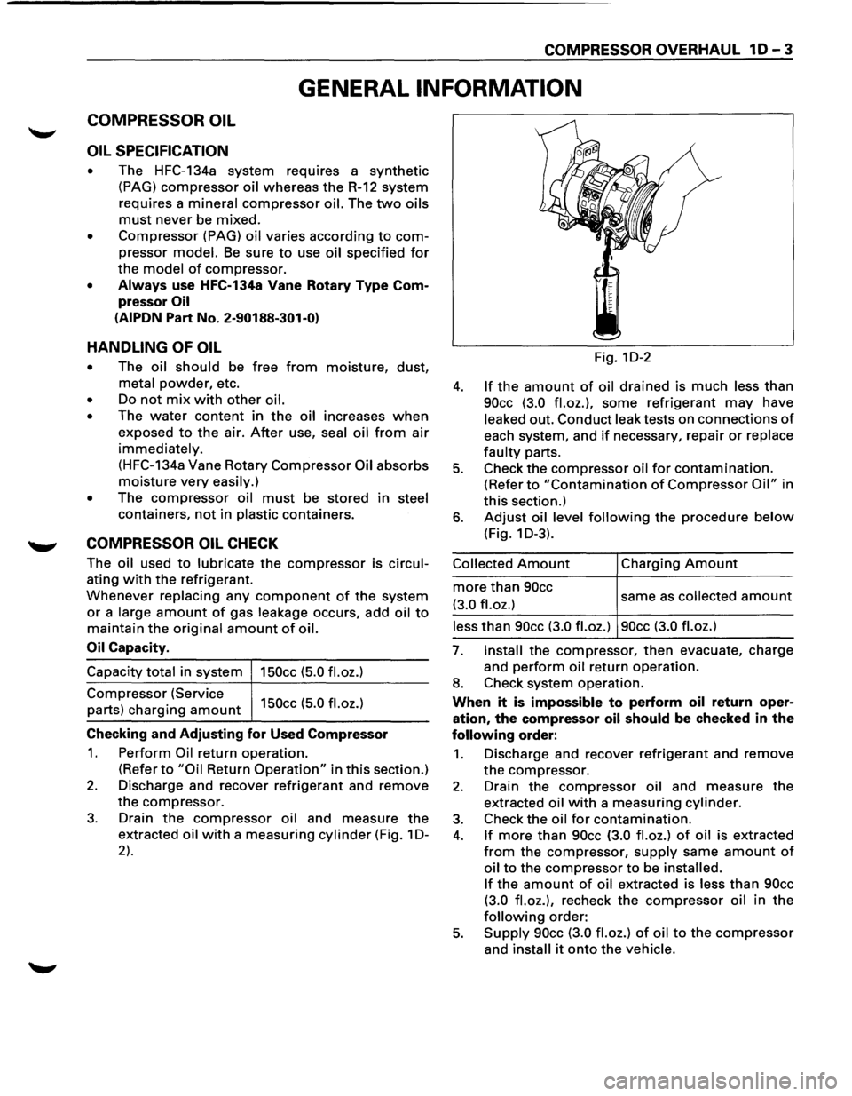
extracted oil with a measuring cylinder (Fig. 1 D-
2).
Fig. 1D-2
4. If the amount of oil drained is much less than
90cc (3.0 fl.oz.), some refrigerant may have
leaked out. Conduct leak tests on connections of
each system, and if necessary, repair or replace
faulty parts.
5. Check the compressor oil for contamination.
(Refer to "Contamination of Compressor Oil" in
this section.)
6. Adjust oil level following the procedure below
(Fig. 1 D-3).
Collected Amount
more than 90cc
(3.0 fl.oz.)
Charging Amount
same as collected amount
less than 90cc (3.0 fl.oz.) 90cc (3.0 fl.oz.)
7. Install the compressor, then evacuate, charge
and
perform oil return operation.
8. Check system operation.
When it is impossible to perform oil return oper
ation, the compressor oil should be checked in the
following order:
1. Discharge and recover refrigerant and remove
the compressor.
2. Drain the compressor oil and measure the
extracted oil with a measuring cylinder.
3. Check the oil for contamination.
4. If more than 90cc (3.0 fl.oz.) of oil is extracted
from the compressor, supply same amount of
oil to the compressor to be installed.
If
the amount of oil extracted is less than 90cc
(3.0 fl.oz.),
recheck the compressor oil in the
following order:
5. Supply 90cc (3.0 fl.oz.) of oil to the compressor
and install it onto the vehicle.
Page 631 of 1928
Mixing ratio(%) 0 10 20 30 40 50
~
' -10
'
1
' -30
~ -40
In case of 8.5 lit total cooling system capacity
Mixing Anti-freeze
Water: solution: ratio (%) lit. (U.S. gal) lit. (U.S. gal.)
0 0 0
8.5 (2.2) 10 0.9 (0.3) 7.6 (2.0) 15
1.3 (0.4) 7.2 (1.9) 20 1.7 (0.5) 6.8 (1.8)
25 2.1 (0.6) 6.4 (1.7) 30 2.6 (0.7) 5.9 (1.6)
35 3.0 (0.8) 5.5
(1.5) 40 3.4 (0.9) 5.1 (1.3)
45 3.8 (1.0) 4.7 (1.2) 50 4.3 (1.1)
4.2 (1.1)
Fig. 68-5
ENGINE COOLING 68-3
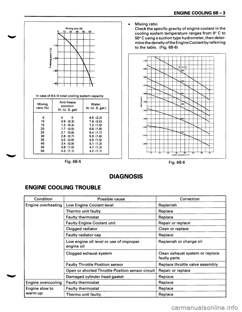
• Mixing ratio
Check
the specific gravity of engine coolant in the
cooling system temperature ranges from oo C to
50° C using a suction type hydrometer, then deter
mine the densityofthe Engine Coolant by referring
to the table. (Fig. 68-6)
1,100 1'-........ ........ ...... .............. Mixing ratio
~"""--r-... 1'-""' 1,1)90
........ ...... ........ ........ .......... '
1,000
'"" 1,07 o......_ 1'-........ I'-.......... I"-........ .......
I"-........ ..........
................. I"-........
'
1,080
....... I"-........ ~ ........ ......
........ "'" ~"""--r--..... 1,050
r-. ........ ~ .......... ......
---
........ ........ 1,040
r-.... !'--.. 1'-0 '"" ~"""--1'-.... ........ 1,03
1--....... ........ r--~ ........
'
1,020
....... ~ 1'-0 ~"""---.... 1,01
...... ,
'
1,000
10 20 30 40 50 60 70 Coolant temperature ("C)
Fig. 68-6
DIAGNOSIS
ENGINE COOLING TROUBLE
Condition Possible cause Correction
Engine
overheating Low Engine Coolant level Replenish
Thermo unit faulty Replace
Faulty
thermostat Replace
Faulty
Engine Coolant unit Repair or replace
Clogged
radiator Clean or replace
Faulty
radiator cap Replace
Low engine oil level or use of improper Replenish or change oil
engine oil
Clogged exhaust system Clean exhaust system or replace
faulty parts
Faulty Throttle Position sensor Replace throttle valve assembly
Open or shorted Throttle Position sensor circuit Repair or replace
Damaged cylinder head gasket Replace
Engine overcooling Faulty thermostat Replace
Engine slow to Faulty thermostat Replace
warm-up Thermo unit faulty Replace
Page 655 of 1928
ENGINE ELECTRICAL 601-1
SECTION 60
ENGINE ELECTRICAL
CONTENTS
Battery . . ..... . ...... . ... . .... . .... ..... .... . .... .. .... . .... . . ... . . . .... . . .. . . .... . ... . ... . .... . . .. ... . .... . . ... . ... . . .. . Section 601
Cranking System
........... ... . ... . .... . .... . . .... . .... .
. ... . . .... . .... . .... . . ... ...
.. .... . . ..... . .... . ......... ... Section 602
Charging System ..... .... . . .............. .... . .... . . .. .. . . ... . . ... . . ... . . ... . . ........ .... . . ..... .. .... . ... . .... . .. Section 603
Ignition System (V6 3.2L) .. .... ...... ...... .. .. .. .... ...... .... .. .... .... .... ...... ...... ...... .......... .... Section 6D4A
SECTION 601
BATTERY
CONTENTS
General Description ............................... 6D1-1
Diagnosis .............................................. 6D1-1
On-Vehicle Service ................................ 6D1-3
Battery Charging ................................ 6D1-3
Jump Starting .................................... 6D1-3
Removal and Installation of The Battery . . 6D1-4
Main Data and Specifications . . . . . . . . . . . . . . . . . . 6D1-4
GENERAL DESCRIPTION
There are six battery fluid caps at the top of the
battery. These are covered by a paper
label.
The battery is completely sealed except for the six
small vent holes at the side. These vent holes per
mit the escape of small amounts of gas generated
by the battery.
This type
of battery has the following advantages
over
conventional batteries:
1. There is no need to add water during the entire
service
life of the battery.
2. The battery protects itself against overcharging.
The battery
will refuse to accept an excessive
charge. (A
conventional battery will accept an excessive
charge,
resulting in gassing and loss of battery
fluid.)
3. The battery is much less vulnerable to self
discharge than a conventional type battery.
DIAGNOSIS
1. VISUAL INSPECTION
Inspect the battery for obvious physical damage,
such
as a cracked or broken case, which would per
mit electrolyte loss.
Replace
the battery if obvious physical damage is
discovered during inspection.
Check
for any other physical damage and correct it
as necessary. If not, proceed to Step 2.
2. HYDROMETER CHECK
There is a built-in hydrometer (Charge test indica
tor) at the top of the battery. It is designed to be
used during diagnostic procedures. Before
trying to read the hydrometer,
carefully
clean
the upper battery surface.
If your work area is poorly lit, additional light may
be necessary
to read the hydrometer (Fig. 6D1-1).
a. BLUE RING OR DOT VISIBLE -Go to Step
4.
b. BLUE RING OR DOT NOT VISIBLE -Go to
Step 3.