open hood ISUZU TROOPER 1995 Owner's Guide
[x] Cancel search | Manufacturer: ISUZU, Model Year: 1995, Model line: TROOPER, Model: ISUZU TROOPER 1995Pages: 1928
Page 1746 of 1928
9J-122 Supplemental Restraint System
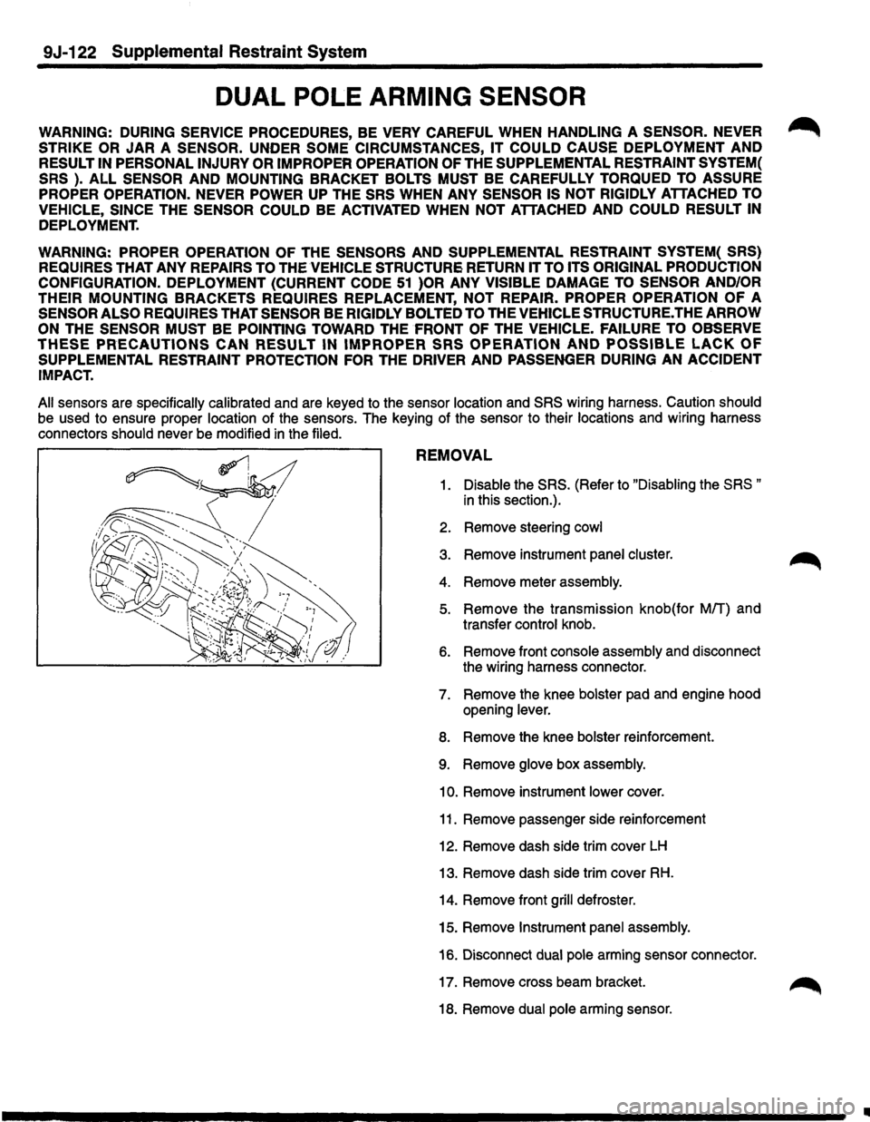
DUAL POLE ARMING SENSOR
WARNING: DURING SERVICE PROCEDURES, BE VERY CAREFUL WHEN HANDLING A SENSOR. NEVER ~
STRIKE OR JAR A SENSOR. UNDER SOME CIRCUMSTANCES, IT COULD CAUSE DEPLOYMENT AND
RESULT IN PERSONAL INJURY OR IMPROPER OPERATION OF THE SUPPLEMENTAL RESTRAINT SYSTEM(
SRS
). ALL SENSOR AND MOUNTING BRACKET BOLTS MUST BE CAREFULLY TORQUED TO ASSURE
PROPER OPERATION. NEVER POWER
UP THE SRS WHEN ANY SENSOR IS NOT RIGIDLY ATTACHED TO
VEHICLE, SINCE
THE SENSOR COULD BE ACTIVATED WHEN NOT ATTACHED AND COULD RESULT IN
DEPLOYMENT.
WARNING: PROPER OPERATION OF THE SENSORS AND SUPPLEMENTAL RESTRAINT SYSTEM( SRS)
REQUIRES
THAT ANY REPAIRS TO THE VEHICLE STRUCTURE RETURN IT TO ITS ORIGINAL PRODUCTION
CONFIGURATION.
DEPLOYMENT (CURRENT CODE 51 )OR ANY VISIBLE DAMAGE TO SENSOR AND/OR
THEIR MOUNTING
BRACKETS REQUIRES REPLACEMENT, NOT REPAIR. PROPER OPERATION OF A
SENSOR ALSO REQUIRES THAT SENSOR BE RIGIDLY BOLTED TO THE VEHICLE STRUCTURE. THE ARROW
ON
THE SENSOR MUST BE POINTING TOWARD THE FRONT OF THE VEHICLE. FAILURE TO OBSERVE
THESE PRECAUTIONS CAN RESULT IN IMPROPER SRS OPERATION AND POSSIBLE LACK OF
SUPPLEMENTAL RESTRAINT PROTECTION FOR THE DRIVER AND PASSENGER DURING AN ACCIDENT
IMPACT.
All
sensors are specifically calibrated and are keyed to the sensor location and SRS wiring harness. Caution should
be used to ensure proper location of the sensors. The keying of the sensor to their locations and wiring harness
connectors should never be modified
in the filed.
REMOVAL
1. Disable the SRS. (Refer to "Disabling the SRS "
in this section.).
2. Remove steering
cowl
3. Remove instrument panel cluster. ~
4. Remove meter assembly.
5. Remove the transmission knob(for Mff) and
transfer control knob.
6. Remove front console assembly and disconnect
the wiring harness connector.
7. Remove the knee bolster pad and engine hood
opening lever.
8. Remove the knee bolster reinforcement.
9. Remove glove box assembly.
10. Remove instrument lower cover.
11. Remove passenger side reinforcement
12. Remove dash side trim cover
LH
13. Remove dash side trim cover RH.
14. Remove front grill defroster.
15. Remove
Instrument panel assembly.
16. Disconnect
dual pole arming sensor connector.
17. Remove cross beam bracket.
18. Remove
dual pole arming sensor.
II
Page 1747 of 1928
INSTALLATION
1. Install dual pole arming sensor and tighten to
specified torque.
Torque: 26N·m(19 lb·ft.).
2. Install cross beam bracket.
3. Connect dual pole arming sensor connector.
4. Install instrument panel assembly.
5. Install front grill defroster.
6. Install dash side trim cover RH.
7. Install dash side trim cover LH.
8.
Install passenger side reinforcement
9. Install instrument lower cover.
1
0. Install glove box assembly.
11. Install the knee bolster reinforcement.
12.
Install the knee bolster pad and engine hood
opening
lever.
13. Install front console assembly and connect the
wiring harness connector.
14.
Install the transmission knob(for M/T) and
transfer control knob.
15.
Install meter assembly.
16. Install instrument panel cluster.
17. Install steering cowl
18. Enable the SRS (Refer to "Enabling the SRS" in
this section.).
Supplemental :Restraint System 9J-123
Page 1751 of 1928
Supplemental Restraint System 9J-127
SRS COIL ASSEMBLY
WARNING: SAFETY PRECAUTIONS MUST BE FOLLOWED WHEN HANDLING A DEPLOYED INFLATOR
MODULE{AIR
BAG). AFTER DEPLOYMENT, THE INFLATOR MODULE{AIR BAG) SURFACE MAY CONTAIN A
SMALL AMOUNT OF SODIUM HYDROXIDE, A BY-PRODUCT OF THE DEPLOYMENT REACTION, THAT IS
IRRITATING TO
THE SKIN AND EYES. MOST OF THE POWDER ON THE INFLATOR MODULE (AIR BAG )IS
HARMLESS.
AS A PRECAUTION, WEAR GLOVES AND SAFETY GLASSES WHEN HANDLING A DEPLOYED
INFLATOR MODULE {AIR BAG ), AND WASH YOUR HANDS WITH MILD SOAP AND WATER AFTERWARDS.
WARNING: WHEN CARRYING A LIVE INFLATOR MODULE {AIR BAG ), MAKE SURE THE BAG AND TRIM
COVER
ARE POINTED AWAY FROM YOU. NEVER CARRY INFLATOR MODULE {AIR BAG )BY THE WIRES OR
CONNECTOR ON
THE UNDERSIDE OF MODULE. IN THE CASE OF AN ACCIDENTAL DEPLOYMENT, THE BAG
WILL THEN DEPLOY WITH MINIMAL CHANCE OF INJURY. WHEN PLACING A LIVE INFLATOR MODULE (AIR
BAG ) ON A BENCH OR OTHER SURFACE, ALWAYS FACE BAG AND TRIM COVER UP, AWAY FROM THE
SURFACE. NEVER REST A STEERING COLUMN ASSEMBLY ON THE STEERING WHEEL WITH THE INFLATOR
MODULE (AIR BAG) FACE DOWN AND COLUMN VERTICAL. THIS IS NECESSARY SO THAT A FREE SPACE
IS PROVIDED TO
ALLOW THE INFLATOR MODULE { AIR BAG ) TO EXPAND IN THE UNLIKELY EVENT OF
ACCIDENTAL
DEPLOYMENT. OTHERWISE, PERSONAL INJURY COULD RESULT.
NOTE:
In the event deployment has occurred, inspect coil assembly wire for any signs of scorching, melting or any
other damage due to excessive heat.
If the coil has been damaged, replace it.
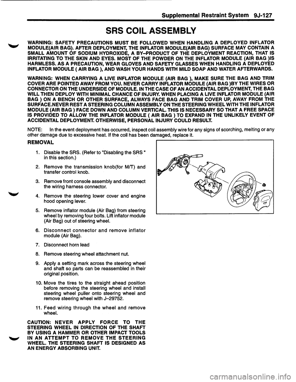
REMOVAL ~------------------------------------------,
1. Disable the SRS. (Refer to "Disabling the SRS"
in this section.)
2. Remove the transmission knob(for
MIT) and
transfer
control knob.
3. Remove front console assembly and disconnect
the wiring harness connector.
4. Remove the steering lower cover and engine
hood opening
lever.
5. Remove inflator module (Air Bag) from steering
wheel by removing four bolts. Lift inflator module
(Air Bag) out of steering wheel.
6. Disconnect connector and remove inflator
module (Air Bag).
7. Disconnect horn lead
8. Remove steering wheel attachment nut.
9. Apply a setting mark across the steering wheel
and shaft so parts can be reassembled in their
original position.
10. Move the tires to the straight ahead position
before removing the steering
wheel and install
steering wheel puller onto steering wheel and
remove steering
wheel with J-29752.
11. Feed wiring through the wheel and remove
wheel.
CAUTION:
NEVER APPLY FORCE TO THE
STEERING WHEEL IN DIRECTION OF THE SHAFT
BY USING A HAMMER OR OTHER IMPACT TOOLS
~ IN AN ATTEMPT TO REMOVE THE STEERING
WHEEL. THE STEERING SHAFT IS DESIGNED AS
AN ENERGY ABSORBING UNIT.
Page 1752 of 1928
9J-128 Supplemental Restraint System
12. Remove steering column cover.
13. Disconnect the wiring harness connectors ~
located base of steering column.
14. Remove the combination switch assembly with
SRScoil.
NOTE: SRS
coil is a part of combination switch
assembly, which
cannot be replaced individually.
Therefore, be sure not to remove the
SRS coil from the
combination switch assembly.
INSTALLATION
1. Install the combination switch assembly with
SRScoil.
2. Connect the wiring harness connector located In
base of steering column.
3. Turn the SRS coil clockwise to full, return about
3 turns and align the neutral mark.
CAUTION: WHEN TURNING THE SRS COIL
CLOCKWISE TO FULL, STOP TURNING IF
RESISTANCE IS FELT. FORCED FURTHER
TURNING MAY CAUSE DAMAGE TO THE CABLE IN
THE SRS COIL.
4. Install steering column cover.
CAUTION: WHEN INSTALLING THE STEERING
COLUMN COVER, BE SURE TO WIRE (THROUGH ~
EACH HARNESS) AS ILLUSTRATED SO THAT THE
HARNESSES OF STARTER SWITCH,COMBINATION
SWITCH
AND SRS COIL MAY NOT CATCH WIRING.
5. Install the steering wheel and align the setting
marks.
6. Tighten the steering fixing nut to the specified
torque.
Torque : 34N·m(25 lb·ft.).
7. Connect horn lead connector.
8. Connect inflator module to 2-way yellow wiring
harness connector.
9. Install inflator module into steering wheel and
torque fasteners.
NOTE: Always replace inflator module {Air Bag)
fasteners with new fasteners. Never reuse old fasteners.
Torque: 8N·m(69 lb·ln.)
10. Install the steering lower cover and engine hood
opening lever.
11. Install front console assembly and connect the
wiring harness connector.
12. Install the transmission knob{for M/T) and
transfer control knob. ~
13. Enable the SRS (Refer to "Enabling the SRS" in
this section.).
•
Page 1753 of 1928
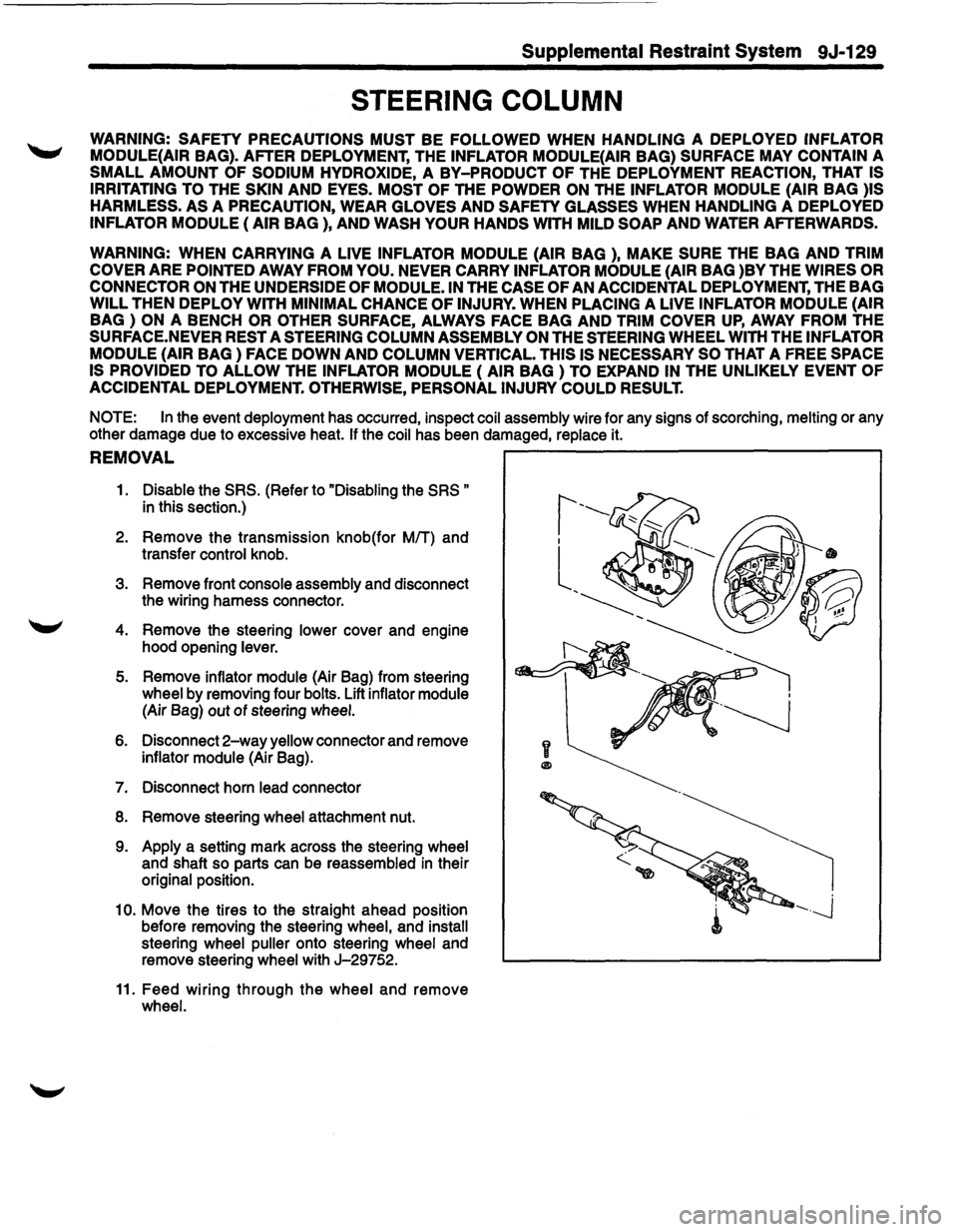
Supplemental Restraint System 9J-129
STEERING COLUMN
WARNING: SAFETY PRECAUTIONS MUST BE FOLLOWED WHEN HANDLING A DEPLOYED INFLATOR
MODULE{AIR
BAG). AFTER DEPLOYMENT, THE INFLATOR MODULE{AIR BAG) SURFACE MAY CONTAIN A
SMALL AMOUNT OF SODIUM HYDROXIDE, A BY-PRODUCT OF THE DEPLOYMENT REACTION, THAT IS
IRRITATING TO
THE SKIN AND EYES. MOST OF THE POWDER ON THE INFLATOR MODULE (AIR BAG )IS
HARMLESS.
AS A PRECAUTION, WEAR GLOVES AND SAFETY GLASSES WHEN HANDLING A DEPLOYED
INFLATOR MODULE (AIR BAG ), AND WASH YOUR HANDS WITH MILD SOAP AND WATER AFTERWARDS.
WARNING: WHEN CARRYING A LIVE INFLATOR MODULE {AIR BAG ), MAKE SURE THE BAG AND TRIM
COVER
ARE POINTED AWAY FROM YOU. NEVER CARRY INFLATOR MODULE (AIR BAG )BY THE WIRES OR
CONNECTOR ON
THE UNDERSIDE OF MODULE. IN THE CASE OF AN ACCIDENTAL DEPLOYMENT, THE BAG
WILL THEN DEPLOY WITH MINIMAL CHANCE OF INJURY. WHEN PLACING A LIVE INFLATOR MODULE (AIR
BAG ) ON A BENCH OR OTHER SURFACE, ALWAYS FACE BAG AND TRIM COVER UP, AWAY FROM THE
SURFACE.NEVER REST A STEERING COLUMN ASSEMBLY ON THE STEERING WHEEL WITH THE INFLATOR
MODULE {AIR
BAG) FACE DOWN AND COLUMN VERTICAL. THIS IS NECESSARY SO THAT A FREE SPACE
IS PROVIDED TO
ALLOW THE INFLATOR MODULE (AIR BAG) TO EXPAND IN THE UNLIKELY EVENT OF
ACCIDENTAL
DEPLOYMENT. OTHERWISE, PERSONAL INJURY COULD RESULT.
NOTE:
In the event deployment has occurred, inspect coil assembly wire for any signs of scorching, melting or any
other damage due to excessive heat.
If the coil has been damaged, replace it.
REMOVAL ~--------------------------~
1. Disable the SRS. (Refer to "Disabling the SRS "
in this section.)
2. Remove the transmission knob(for MIT) and
transfer
control knob.
3. Remove front console assembly and disconnect
the wiring harness connector.
4. Remove the steering lower cover and engine
hood opening
lever.
5. Remove inflator module (Air Bag) from steering
wheel by removing four bolts. Lift inflator module
(Air Bag) out of steering wheel.
6. Disconnect 2-way yellow connector and remove
inflator module (Air Bag).
7. Disconnect horn lead connector
8. Remove steering wheel attachment nut.
9. Apply a setting mark across the steering wheel
and shaft so parts can be reassembled in their
original position.
1
0. Move the tires to the straight ahead position
before removing the steering
wheel, and install
steering wheel puller onto steering wheel and
remove steering
wheel with J-29752.
11. Feed wiring through the wheel and remove
wheel.
y
®
Page 1755 of 1928
1 o. Connect the wiring harness connector located
base of steering column.
11. Turn the SRS coil clockwise to full, return about
3 turns and align the neutral mark.
CAUTION: WHEN TURNING THE SRS COIL
CLOCKWISE TO FULL, STOP TURNING IF
RESISTANCE IS FELT. FORCED FURTHER
TURNING MAY CAUSE DAMAGE TO THE CABLE IN
THE SRS COIL.
12. Install steering column cover.
CAUTION: WHEN INSTALLING THE STEERING
COLUMN COVER,
BE SURE TO WIRE {THROUGH
EACH HARNESS) AS ILLUSTRATED SO THAT THE
HARNESSES OF STARTER SWITCH,COMBINATION
SWITCH
AND SRS COIL MAY NOT CATCH WIRING.
13. Install the steering wheel and align the setting
marks.
14. Tighten the steering fixing nut to the specified
torque.
Torque: 34N·m(25 lb·ft.).
15. Connect horn lead connecor.
16. Connect inflator module to
2-way yellow wiring
harness connector.
17.
Install inflator module into steering wheel and
torque fasteners.
Torque: 8N·m(69 lb-in.)
18. Install the steering lower cover and engine hood
opening lever.
19.
Install front console assembly and connect the
wiring harness connector.
20.
Install the transmission knob(for M/T) and
transfer control knob.
21. Enable the
SRS (Refer to "Enabling the SRS" in
this section.).
Supplemental Restraint System 9J-131
Page 1784 of 1928
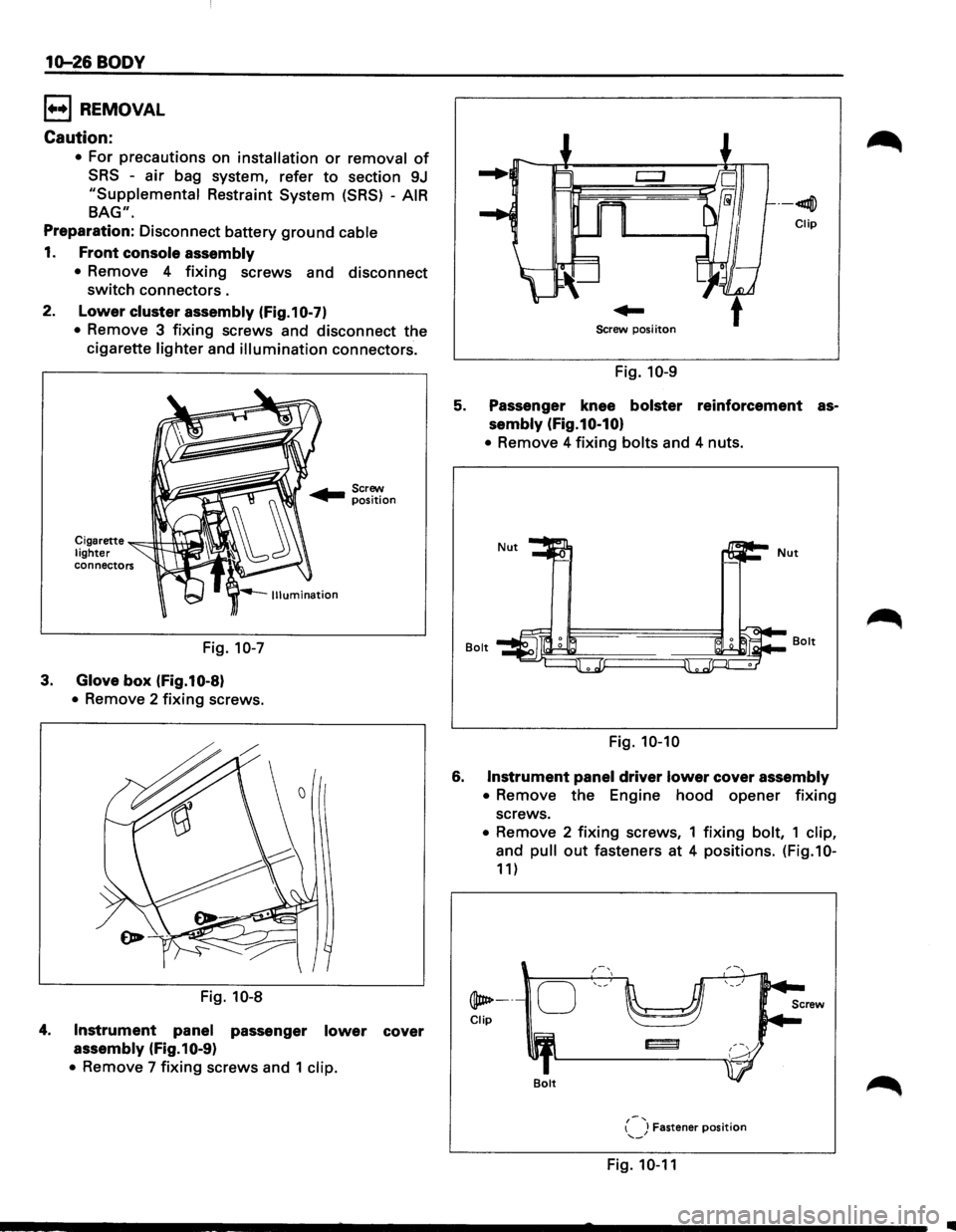
10-26 BODY
l••l REMOVAL
Caution:
• For precautions on installation or removal of
SRS -air bag system, refer to section 9J
"Supplemental Restraint System (SRS) -AIR
BAG".
Preparation: Disconnect battery ground cable
1. Front console assembly
•
Remove 4 fixing screws and disconnect
switch connectors .
2. Lower cluster assembly (Fig.10-7)
• Remove 3 fixing screws and disconnect the
cigarette
lighter and illumination connectors.
Cigarette ~c--!H---1\.+.....,. lighter connectors
Fig. 10-7
3. Glove box (Fig.10-8)
• Remove 2 fixing screws.
Fig.
10-8
4. Instrument panel passenger lower cover
assembly (Fig.10-9)
• Remove 7 fixing screws and 1 clip.
--41llj])
Clip
Screw posi iton
Fig. 10-9
5. Passenger knee bolster reinforcement as
sembly (Fig.10-10)
• Remove 4 fixing bolts and 4 nuts.
Bolt
Fig. 10-10
6. Instrument panel driver lower cover assembly
•
Remove the Engine hood opener fixing
screws.
• Remove 2 fixing screws, 1 fixing bolt, 1 clip,
and pull out fasteners at 4 positions. (Fig.10-
11)
@ate----
Clip
Bolt
{-J Fastener position '--
Fig. 10-11
..
Page 1787 of 1928
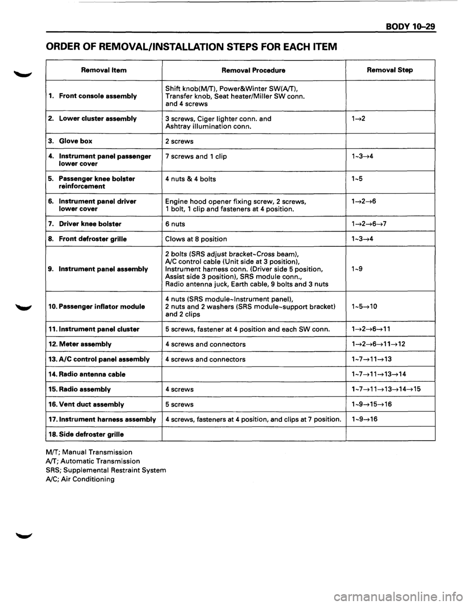
ORDER OF REMOVAL/INSTALLATION STEPS FOR EACH ITEM
Removal Item
1. Front console assembly
2. Lower cluster assembly
3. Glove box
4. Instrument panel passenger lower cover
5. Passenger knee bolster reinforcement
6. Instrument panel driver lower cover
7. Driver knee bolster
8. Front defroster grille
9. Instrument panel assembly
10. Passenger inflator module
11.1nstrument panel cluster
12. Meter assembly
13. A/C control panel assembly
14. Radio antenna cable
15. Radio assembly
16. Vent duct assembly
17 .Instrument harness assembly
18. Side defroster grille
MfT; Manual Transmission
A/T;
Automatic Transmission Removal
Procedure
Shift
knob(MfT), Power&Winter SW(A/T),
Transfer knob, Seat heater/Miller SW conn.
and 4 screws
3 screws, Ciger lighter conn. and
Ashtray illumination conn.
2 screws
7 screws and 1 clip
4 nuts & 4 bolts
Engine hood opener fixing screw, 2 screws, 1 bolt, 1 clip and fasteners at 4 position.
6 nuts
Claws at 8 position
2 bolts (SRS adjust bracket-Cross beam), A!C control cable (Unit side at 3 position), Instrument harness conn. (Driver side 5 position,
Assist side 3 position), SRS module conn.,
Radio antenna juck, Earth
cable, 9 bolts and 3 nuts
4 nuts (SRS module-Instrument panel), 2 nuts and 2 washers (SRS module-support bracket)
and 2 clips
5 screws, fastener at 4 position and each SW conn.
4 screws and connectors
4 screws and connectors
4 screws
5 screws
4 screws, fasteners at 4 position, and clips at 7 position.
SRS; Supplemental Restraint System
A!C; Air Conditioning
BODY 10-29
Removal Step
1~2
1~3~4
1~5
1~2~6
1~2~6~7
1-3~4
1~9
1-5~10
1~2~6~11
1~2~6~11~12
1-7~11~13
1-7~11~13~14
1~7~11~13~14~15
1-9~15~16
1-9~16