width ISUZU TROOPER 1995 Workshop Manual
[x] Cancel search | Manufacturer: ISUZU, Model Year: 1995, Model line: TROOPER, Model: ISUZU TROOPER 1995Pages: 1928
Page 15 of 1928
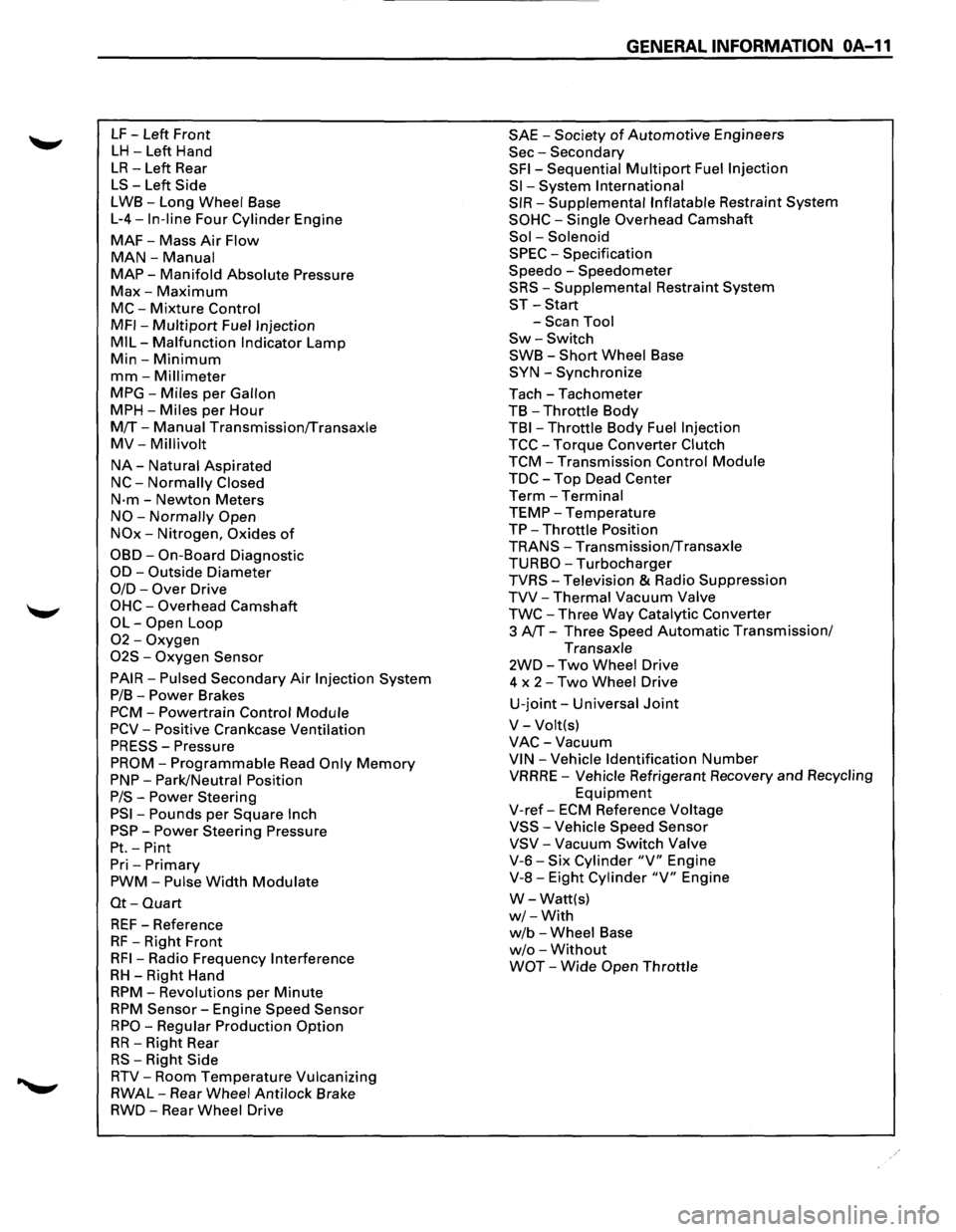
LF -Left Front
LH -Left Hand
LR-Left Rear
LS-Left Side
LWB-Long Wheel Base
L-4-In-line Four Cylinder Engine
MAF-Mass Air Flow
MAN-Manual
MAP-Manifold Absolute Pressure
Max-Maximum
MC-Mixture Control
MFI-Multipart Fuel Injection
MIL-Malfunction Indicator Lamp
Min-Minimum
mm-Millimeter
MPG-Miles per Gallon
MPH-Miles per Hour
M!f-Manual Transmission!fransaxle
MV-Millivolt
NA-Natural Aspirated
NC-Normally Closed
N·m-Newton Meters
NO-Normally Open
NOx-Nitrogen, Oxides of
OBD-On-Board Diagnostic
OD-Outside Diameter
0/D-Over Drive
OHC-Overhead Camshaft
OL-Open Loop
02-Oxygen
02S -Oxygen Sensor
PAIR-Pulsed Secondary Air Injection System
P/B-Power Brakes
PCM-Powertrain Control Module
PCV-Positive Crankcase Ventilation
PRESS-Pressure
PROM-Programmable Read Only Memory
PNP-Park/Neutral Position
P/S-Power Steering
PSI-Pounds per Square Inch
PSP-Power Steering Pressure
Pt.-Pint
Pri -Primary
PWM-Pulse Width Modulate
Ot-Quart
REF-Reference
RF -Right Front
RFI-Radio Frequency Interference
RH-Right Hand
RPM-Revolutions per Minute
RPM Sensor-Engine Speed Sensor
RPO-Regular Production Option
RR-Right Rear
RS-Right Side
RTV-Room Temperature Vulcanizing
RWAL-Rear Wheel Anti lock Brake
RWD-Rear Wheel Drive
GENERAL INFORMATION OA-11
SAE -Society of Automotive Engineers
Sec-Secondary
SFI-Sequential Multipart Fuel Injection
Sl-System International
SIR-Supplemental Inflatable Restraint System
SOHC-Single Overhead Camshaft
Sol -Solenoid
SPEC -Specification
Speedo -Speedometer
SRS-Supplemental Restraint System
ST-Start
-Scan Tool
Sw-Switch
SWB-Short Wheel Base
SYN-Synchronize
Tach-Tachometer
TB
-Throttle Body
TBI-Throttle Body Fuel Injection
TCC-Torque Converter Clutch
TCM-Transmission Control Module
TDC-Top Dead Center
Term-Terminal
TEMP-Temperature
TP-Throttle Position
TRANS-Transmission!fransaxle
TURBO-Turbocharger
TVRS-Television & Radio Suppression
TVV-Thermal Vacuum Valve
TWC-Three Way Catalytic Converter
3
AfT-Three Speed Automatic Transmission/
Transaxle
2WD-Two Wheel Drive
4 x
2-Two Wheel Drive
U-joint-Universal Joint
V-Volt(s)
VAC-Vacuum
VIN-Vehicle Identification Number
VRRRE -Vehicle Refrigerant Recovery and Recycling
Equipment
V-ref-ECM Reference Voltage
VSS-Vehicle Speed Sensor
VSV-Vacuum Switch Valve
V-6-Six Cylinder "V" Engine
V-8-Eight Cylinder "V" Engine
W-Watt(s)
w/-With
w/b -Wheel Base
w/o -Without
WOT-Wide Open Throttle
Page 201 of 1928
WHEELS AND TIRES 3E-1
SECTION 3E
WHEELS AND TIRES
W CAUTION:
When fasteners are removed, always reinstall them at the same location from which they were removed.
If a fastener needs to be replaced, use the correct part number fastener for that application. If the correct
part
number fastener is not available, a fastener of equal size and strength (or stronger) may be used.
Fasteners
that are not reused, and those requiring thread locking compound, will be called out. The correct
torque value must be used when installing fasteners that require it. If the above conditions are not
followed, parts or system damage could result.
CONTENTS
General Description . . . . . . . . . . . . . . . . . . . . . . . . . . . . . . . 3 E -1 Unit Repair .......................................... 3E-7
Diagnosis ........................................... 3E-2 Tires ............................................... 3E-7
Irregular and Premature Wear ................ 3E-2 Wheels ............................................ 3E-7
Inflation of Tires ................................. 3 E- 3 General Balance Procedure ................... 3E-8
Diagnosis List. . . . . . . . . . . . . . . . . . . . . . . . . . . . . . . . . . . . 3 E- 3 Balancing Wheel and Tire ...................... 3E-8
On-Vehicle Service ................................ 3E-6 Main Data and Specifications .................... 3E-9
Wheels ............................................ 3E-6 General Specifications ......................... 3E-9
Torque Specifications .......................... 3E-9
GENERAL DESCRIPTION
Replacement wheels or tires must be equivalent to
the originals in load capacity, specified dimension
and mounting configuration. Improper size or type
may affect bearing life, brake performance,
speedometer/odometer calibration, vehicle ground
clearance and tire clearance to the body and chassis.
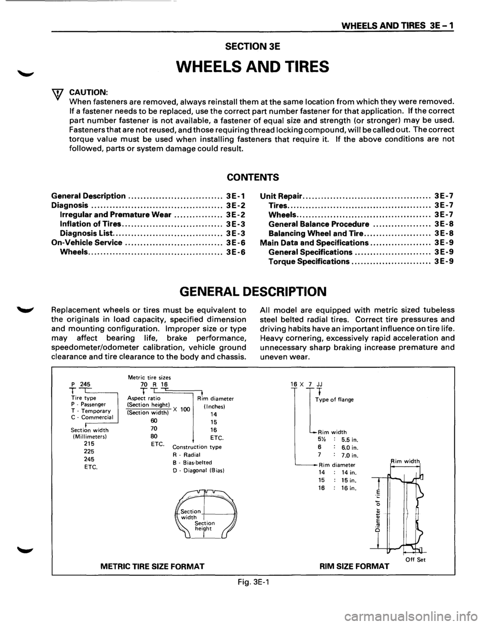
p 245
T Tire type P -Passenger T -Temporary C -Commercial
Section
width (Millimeters) 215 225
245
ETC.
Metric tire sizes 70 R 16 T ,...
Aspect ratio I Rim diameter
(Section height)
(Section
width) X 100 (Inches)
14 60 70
80 ETC.
15
16 ETC.
Construction type
R-Radial
B - Bias-belted
D - Diagonal (Bias)
METRIC TIRE SIZE FORMAT
All model are equipped with metric sized tubeless
steel belted radial
tires. Correct tire pressures and
driving habits have an important influence on tire life.
Heavy cornering, excessively rapid acceleration and
unnecessary sharp braking increase
premature and
uneven wear.
16 X 7 JJ
I
~pe of flange
Rim width 5% 5.5 in.
6 6.0 in. 7 7.0 in.
Rim diameter Rim width
14 14 in. 15 15 in. 16 : 16 in.
I Off Set RIM SIZE FORMAT
Fig. 3E-1
Page 523 of 1928
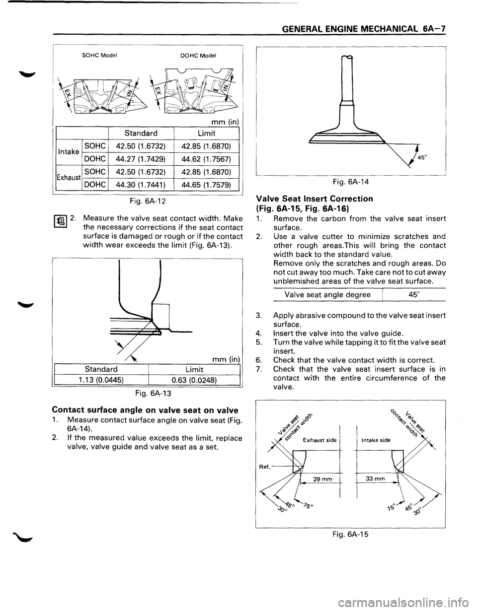
Intake
Exhaust
~ 2.
SOHC Model DOHC Model
mm (in)
Standard Limit
SOHC 42.50 (1.6732)
42.85 (1.6870)
DOHC 44.27 (1.7429)
44.62 (1.7567)
SOHC 42.50 (1.6732) 42.85 (1.6870)
DOHC 44.30 (1.7441) 44.65 (1.7579)
Fig. 6A-12
Measure the
valve seat contact width. Make
the necessary corrections
if the seat contact
surface is damaged or rough
or if the contact
width wear exceeds the limit (Fig. 6A-13).
mm (in)
Standard Limit
1 .13
(0.0445)
0.63 (0.0248)
Fig. 6A-13
Contact surface angle on valve seat on valve
1. Measure contact surface angle on valve seat (Fig.
6A-14).
2. If the measured value exceeds the limit, replace
valve, valve
guide and valve seat as a set.
GENERAL ENGINE MECHANICAL 6A-7
Fig. 6A-14
Valve Seat Insert Correction
(Fig. 6A-15, Fig. 6A-16)
1. Remove the carbon from the valve seat insert
surface.
2. Use a valve cutter to minimize scratches and
other rough areas.This
will bring the contact
width back to the standard value.
Remove only the scratches and rough areas. Do
not cut away too much. Take care not to cut away
unblemished areas of the valve seat surface.
Valve seat angle degree
3. Apply abrasive compound to the valve seat insert
surface.
4. Insert the valve into the valve guide.
5. Turn the valve while tapping it to fit the valve seat
insert.
6. Check that the valve contact width is correct.
7. Check that the valve seat insert surface is in
contact
with the entire circumference of the
valve.
Fig. 6A-15
Page 524 of 1928
&A-8 GENERAL ENGINE MECHANICAL
Fig. 6A-16
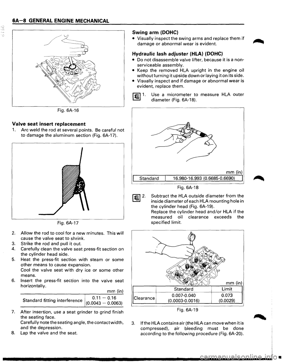
Valve seat insert replacement
1. Arc weld the rod at several points. Be careful not
to damage the aluminum section (Fig. 6A-17).
Fig. 6A-17
2. Allow the rod to cool for a new minutes. This will
cause the valve seat to shrink.
3. Strike the rod and pull it out.
4. Carefully clean the valve seat press-fit section on
the
cylinder head side.
5. Heat the press-fit section with steam or some
other means
to cause expansion.
Cool the valve seat with dry ice or some other
means.
6. Insert the press-fit section into the valve seat
horizontally.
mm (in)
S d df. 0 0 f 0.11-0.16 tan ar 1tt1ng 1nter erence (0.0043 _ 0_
0063 )
7. After insertion,
use a seat grinder to grind finish
the seating face.
Carefully note the seating angle, the contact width,
and the depression.
8. Lap the valve and the seat.
Swing arm (DOHC)
• Visually inspect the swing arms and replace them if
damage or abnormal wear is evident.
Hydraulic lash adjuster (HLA) (DOHC}
• Do not disassemble valve lifter, because it is a non
serviceable assembly.
•
Keep the removed HLA upright in the engine oil
withoutturning it upside down or laying it on its side.
• Visually inspect and if damage or abnormal wear is
evident,
replace them.
[§) 1. Use a micrometer to measure HLA outer
diameter (Fig. 6A-18).
mm (in)
Standard 16.980-16.993
(0.6685-0.6690) I
Fig.
6A-18
Subtract the HLA outside diameter
from the
inside diameter
of each HLA mounting hole in
the
cylinder head (Fig. 6A-19).
Replace the cylinder head and/or HLA if the
measured
oil clearance exceeds the
specified
limit.
Clearance 0.007-0.040
(0.0003-0.0016)
Fig. 6A-19
mm (in)
0.073
(0.0029)
3. lfthe HLA contains air (the HLA can move when it is
compressed). air
bleeding must be done
according
to the following procedure (Fig. 6A-20).
•
Page 540 of 1928
6A-24 GENERAL ENGINE MECHANICAL
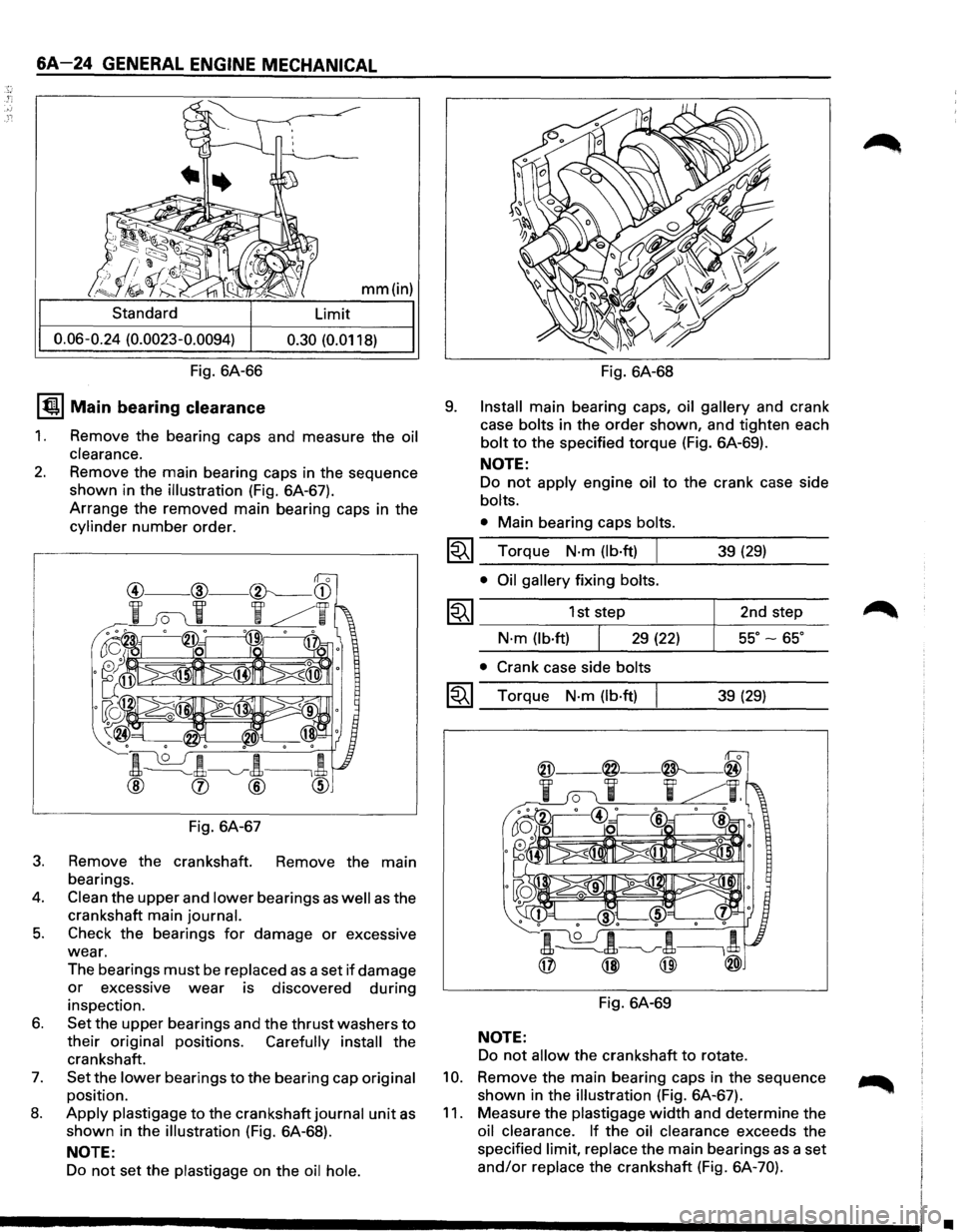
mm(in)
Standard Limit
0.06-0.24 (0.0023-0.0094) 0.30 (0.0118)
Fig. 6A-66 Fig. 6A-68
IQI Main bearing clearance
1. Remove the bearing caps and measure the oil
clearance.
2. Remove the main bearing caps in the sequence
shown in the
illustration (Fig. 6A-67).
Arrange the removed main bearing caps in the
cylinder number order.
Fig. 6A-67
3. Remove the crankshaft. Remove the main
bearings.
4. Clean the upper and lower bearings as well as the
crankshaft main
journal.
5. Check the bearings for damage or excessive
wear.
The bearings
must be replaced as a set if damage
or excessive wear is discovered during
inspection.
6. Set the upper bearings and the thrust washers to
their original positions. Carefully install the
crankshaft.
7. Set the lower bearings to the bearing cap original
position.
8. Apply plastigage to the crankshaft journal unit as
shown in the illustration (Fig. 6A-68).
NOTE:
Do not set the plastigage on the oil hole.
9. Install main bearing caps, oil gallery and crank
case
bolts in the order shown, and tighten each
bolt to the specified torque (Fig. 6A-69).
~
~
~
NOTE:
Do not apply engine oil to the crank case side
bolts.
•
Main bearing caps bolts.
Torque N·m (lb·ft) I 39 (29)
• Oil gallery fixing bolts.
1st step 2nd step
N·m (lb·ft) 29 (22) 55°-65°
• Crank case side bolts
Torque N·m (lb·ft) 39 (29)
Fig. 6A-69
NOTE:
Do not allow the crankshaft to rotate.
10. Remove the main bearing caps in the sequence
shown in the
illustration (Fig. 6A-67).
11. Measure the plastigage width and determine the
oil clearance. If the oil clearance exceeds the
specified
limit, replace the main bearings as a set
and/or replace the crankshaft (Fig. 6A-70).
•
Page 545 of 1928
1£41• Match the numbered caps with the numbers on
the connecting rods.
Align the punched marks
on the connecting rods and caps.
1'l:::r.1• Apply engine oil to the threads and seating
faces
of the nuts.
• Tighten the nuts
~~~ Torque N·m (lb·ft) 54 (40)
7.
After tightening the cap nuts, check to see that
the crankshaft rotates smoothly.
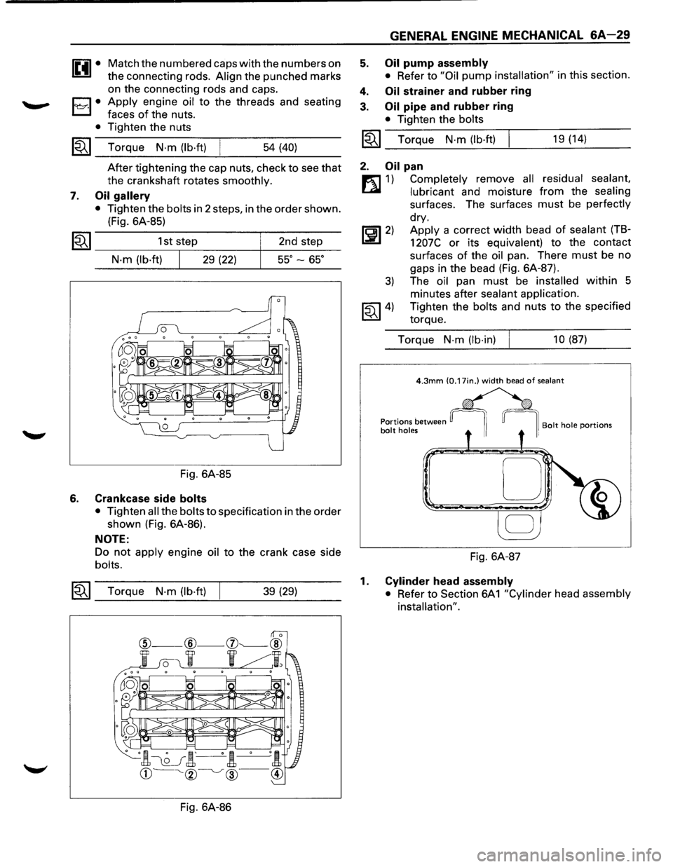
Oil gallery
• Tighten the bolts in 2 steps, in the order shown.
(Fig. 6A-85)
1~1 _________ 1_s_t,s_te~p ________ ~ __ 2_n_d __ st_e~p---
N·m (lb·ft) 29 (22) 55° -65°
Fig. 6A-85
6. Crankcase side bolts
• Tighten all the bolts to specification in the order
shown (Fig. 6A-86).
NOTE:
Do not apply engine oil to the crank case side
bolts.
~~~ Torque N·m (lb·ft) 39 (29)
Fig. 6A-86
5.
4.
3.
GENERAL ENGINE MECHANICAL 6A-29
Oil pump assembly
• Refer to "Oil pump installation" in this section.
Oil strainer and rubber ring
Oil pipe and rubber ring
• Tighten the bolts
I~I_T_o_rq...:....u_e_N_·_m_(:.._lb_·ft....:.)---!. ___ 1_9 _(1_4_) __ _
2. Oil pan
m 1) Completely remove all residual sealant,
~ lubricant and moisture from the sealing
surfaces. The surfaces must be perfectly
dry.
~~~2) Apply a correct width bead of sealant (TB-
1207C or its equivalent) to the contact
surfaces
of the oil pan. There must be no
gaps in the bead (Fig. 6A-87).
3) The oil pan must be installed within 5
minutes after
sealant application.
~~~4) Tighten the bolts and nuts to the specified
torque.
Torque
N-m (lb-in) 10 (87)
D
Fig. 6A-87
1. Cylinder head assembly
• Refer to Section 6A
1 "Cylinder head assembly
installation".
Page 550 of 1928
6A-34 GENERAL ENGINE MECHANICAL
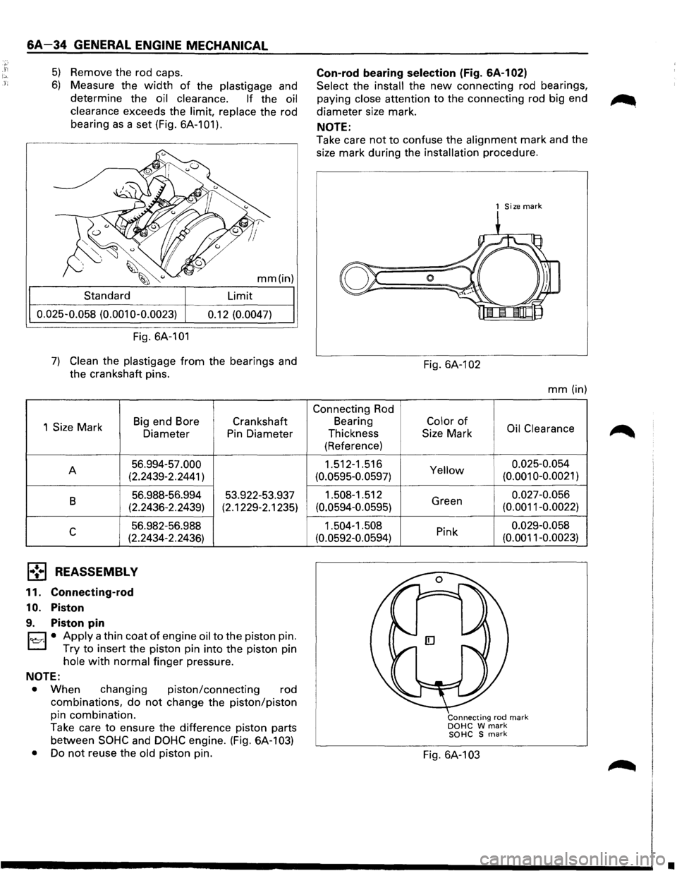
5) Remove the rod caps.
6) Measure the width of the plastigage and
determine the
oil clearance. If the oil
clearance
exceeds the limit, replace the rod
bearing
as a set (Fig. 6A-101).
mm(in)
Standard Limit
0.025-0.058
(0.001 0-0.0023) 0.12 (0.0047)
Fig. 6A-101
7) Clean the plastigage from the bearings and
the crankshaft pins.
1
Size Mark Big
end Bore
Diameter
A 56.994-57.000
(2.2439-2.2441)
B 56.988-56.994
(2.2436-2.2439)
c 56.982-56.988
(2.2434-2.2436)
1,.!•1 REASSEMBLY
11. Connecting-rod
10. Piston
9. Piston pin
Crankshaft
Pin Diameter
53.922-53.937
(2.1229-2.1235)
D • Apply a thin coat of engine oil to the piston pin.
r..::::J Try to insert the piston pin into the piston pin
hole with normal finger pressure.
NOTE:
•
When changing piston/connecting rod
combinations,
do not change the piston/piston
pin combination.
Take care
to ensure the difference piston parts
between
SOHC and DOHC engine. (Fig. 6A-1 03)
• Do not reuse the old piston pin.
Con-rod bearing selection (Fig. GA-1 02)
Select the install the new connecting rod bearings,
paying
close attention to the connecting rod big end
diameter size mark.
NOTE:
Take care not to confuse the alignment mark and the
size mark during the
installation procedure.
Connecting Rod
Bearing
Thickness
(Reference)
1.512-1.516
(0.0595-0.0597)
1.508-1.512
(0.0594-0.0595)
1.504-1.508
(0.0592-0.0594)
1 Size mark
Fig. 6A-1 02
mm (in)
Color of Oil Clearance
Size Mark
Yellow 0.025-0.054 (0.001 0-0.0021)
Green 0.027-0.056
(0.0011-0.0022)
Pink 0.029-0.058
(0.0011-0.0023)
Connecting rod mark DOHC W mark SOHC S mark
Fig. 6A-103
•
Page 557 of 1928
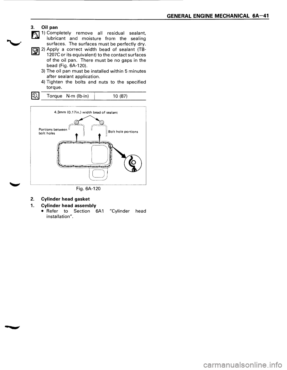
3. Oil pan
m 1) Completely remove all residual sealant,
t..al lubricant and moisture from the sealing
surfaces. The surfaces must be perfectly dry.
li5il 2) Apply a correct width bead of sealant (TB
L::!i!J 1207C or its equivalent) to the contact surfaces
of the oil pan. There must be no gaps in the
bead (Fig. 6A-120).
3) The oil pan must be installed within 5 minutes
after sealant application.
4) Tighten the bolts and nuts to the specified
torque.
1«.1 Torque N·m (lb-in) 10 (87)
4.3mm (0.17in.) width bead of sealant
Fig. 6A-120
2. Cylinder head gasket
1. Cylinder head assembly
• Refer to Section 6A 1 "Cylinder head
installation".
GENERAL ENGINE MECHANICAL 6A-41
Page 561 of 1928
CYLINDER BLOCK
The cylinder block is made of aluminum die-cast
casting
for 75° V-type six cylinders. It has a rear plate
integrated structure and employs a deep skirt. The
cylinder liner is cast and the liner inner diameter and
crankshaft
journal diameter are classified into grades.
The crankshaft is supported by four bearings
of which
width is different between No.2, No.3 and No.1, No.4;
the
width of No.3 bearing on the body side is different
in order
to support the thrust bearing. The bearing cap
is made
of nodular cast iron and each bearing cap uses
four bolts and two side bolts.
CYLINDER HEAD
The cylinder head, made of aluminum alloy casting
employs a pent-roof type combustion chamber with a
spark
plug in the center.
The intake and exhaust
valves are placed in V-type
design. The ports are cross-flow type.
VALVE TRAIN
SOHC: The camshafts on both banks are driven by a
timing
belt to operate the valves via rocker arm.
No
further valve clearance adjustment is
required, due
to the Hydraulic lash adjuster
attachedtotherockerarm.
DOHC: Intake camshaft on the both sides of banks are
driven through a
timing belt, while exhaust
camshaft are driven by the both sides
of intake
camshaft through chains.
The driven camshafts open and
close valves
through swing arms.
Valve clearance is automatically adjusted by
means
of HLA built in the cylinder head.
INTAKE MANIFOLD
SOHC: The intake manifold system is composed ofthe
aluminum cast common chamber and intake
manifold attached with six fuel injectors.
DOHC: The intake manifold system is composed of the
aluminum cast common chamber duct having
the induction
control valve, common chamber
and intake
manifold attached with six fuel
injectors.
EXHAUST MANIFOLD
The exhaust manifold is made of nodular cast iron.
PISTONS AND CONNECTING RODS
Aluminum pistons are used after selecting the grade
that meets the cylinder bore diameter. Each piston has
two compression rings and one oil ring. The piston pin
made
of chromium steel is offset 1 mm toward the
thrust side, and the thrust pressure
of piston to the
cylinder wall varies gradually as the piston travels. The
connecting rods are made
of forged steel. The
connecting rod bearings are graded
for correct size
selection.
ENGINE (V6 3.2L DOHC AND SOHC) 6A1-3
CRANKSHAFT AND BEARINGS
The crankshaft is made of Ductile cast-iron.Pins and
journals are graded for correct size selection for their
bearing.
OIL PUMP
The trochoid-type oil pump is driven by crankshaft.
Operation and service procedures are described in this
section.
ENGINE LUBRICATION
The oil discharged by a trochoid-type oil pump driven
by the crankshaft is fed through full-flow oil filter and
engine
coolant cooled oil cooler up to the oil gallery
provided under the crankshaft bearing cap. The oil is
then
led to the crankshaft journals and cylinder head.
The crank pins are
lubricated with oil from crankshaft
journals through oil holes. Also, an oil jet is fed to each
cylinder from crankshaft journals on the connecting
rod
for piston cleaning. The oil pan flange is sealed with
liquid packing only; do not deform or damage the
flange surface during removal or installation.
Page 609 of 1928
.., ¢'
-
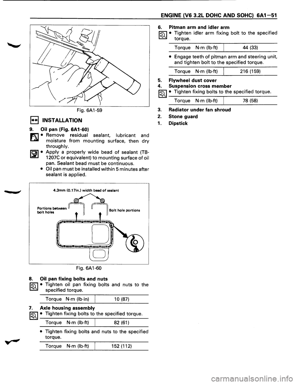
Fig. 6A1-59
1••1 INSTALLATION
9. Oil pan (Fig. 6A1-60)
m • Remove residual sealant, lubricant and
~ moisture from mounting surface, then dry
throughly.
ISPI• Apply a properly wide bead of sealant (TB-
1207C or equivalent) to mounting surface of oil
pan. Sealant bead must be continuous.
• Oil pan must be installed within 5 minutes after
sealant is applied.
4.3mm (0.17in.) width bead of sealant
Portions between bolt holes
Fig. 6A1-60
8. Oil pan fixing bolts and nuts
Bolt hole portions
~ • Tighten oil pan fixing bolts and nuts to the
~ specified torque.
Torque
N·m (lb·in)
10 (87)
7. Axle housing assembly
~~~· Tighten fixing bolts to the specified torque.
Torque
N·m (lb·ft) 82 (61)
• Tighten fixing bolts and nuts to the specified
torque.
Torque
N·m (lb·ft) 152 (112)
ENGINE (V6 3.2L DOHC AND SOHC) 6A 1-51
6. Pitman arm and idler arm
~·
Tighten idler arm fixing bolt to the specified
torque.
Torque
N·m (lb·ft) 44 (33)
• Engage teeth of pitman arm and steering unit,
and tighten
bolt to the specified torque.
Torque
N·m (lb·ft) 216 (159)
5. Flywheel dust cover
4. Suspension cross member
~~~ • Tighten fixing bolts to the specified torque.
Torque
N·m (lb·ft) I 78 (58)
3. Radiator under fan shroud
2. Stone guard
1. Dipstick