width ISUZU TROOPER 1995 Owner's Manual
[x] Cancel search | Manufacturer: ISUZU, Model Year: 1995, Model line: TROOPER, Model: ISUZU TROOPER 1995Pages: 1928
Page 879 of 1928
1. SHIFT CONTROL
The transmission gear is shifted according to the
shift pattern selected by the driver.
~ In shifting gears, the gear ratio is controlled by the
ON/ OFF signal using the 1-2/3-4 shift solenoids and
the 2-3 shift solenoid.
2. BAND APPLY CONTROL
The band apply is controlled when in the 3-2
downshift (engine overrun prevention) and the
garage shift (shock control).
The band
apply solenoid is controlled by the signal
from the Pulse Width Modulation (PWM) to regulate
the
flow of the oil.
3. TORQUE CONVERTER CLUTCH CONTROL
The clutch ON/OFF is controlled by moving the
converter clutch valve through shifting Torque
Converter Clutch
(TCC) solenoid using the ON/OFF
signal.
4. LINE PRESSURE CONTROL
The throttle signal allows the current signal to be
sent
to the force motor. After receiving the current
signal, the force motor activates the pressure
regulator valve to regulate the line pressure.
5. ON-BOARD DIAGNOSTIC SYSTEM
Several malfunction displays can be stored in the
Transmission Control Module (TCM) memory, and
read
out of it afterward.
The serial data lines, which are required for the
testing of the final assembly and the coupling to
other electronic modules, can be regulated by this
function.
6 FAIL-SAFE MECHANISM
If there is a problem in the transmission system, the
TCM will go into a "backup" mode. The vehicle can
still be driven, but the driver must use the gear
lever to shift gears.
7. TORQUE MANAGEMENT CONTROL
The TCM sends the absolute spark advance signal
to the Engine Control Module (ECM) while the
transmission is being shifted, to control the engine
spark timing in compliance with the vehicle running
condition to reduce the shocks caused by the
change of speed.
8. ATF WARNING CONTROL
The oil temperature sensor detects the ATF oil
temperature to control the oil temperature warning,
TCC and the winter mode.
9. ABS CONTROL
When the select lever is at "L" or "R" range, a
signal is sent
to the ABS controller as one of the
ABS control conditions.
AUTOMATIC TRANSMISSION (4L30-E) 7A-7
Page 974 of 1928
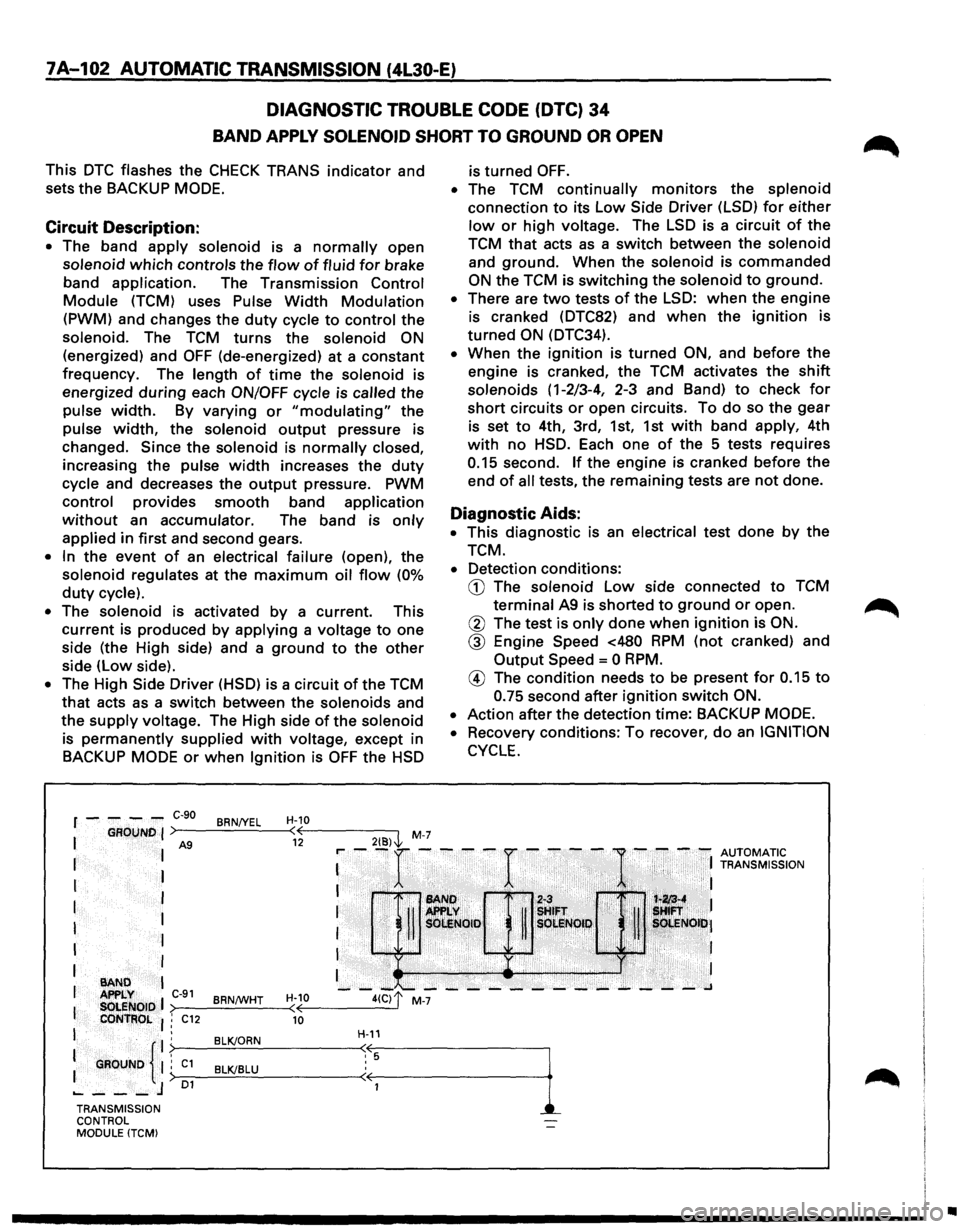
7A-102 AUTOMATIC TRANSMISSION (4L30-E)
DIAGNOSTIC TROUBLE CODE
(DTC) 34
BAND APPLY SOLENOID SHORT TO GROUND OR OPEN
This DTC flashes the CHECK TRANS indicator and
sets the BACKUP
MODE.
Circuit Description:
• The band apply solenoid is a normally open
solenoid
which controls the flow of fluid for brake
band
application. The Transmission Control
Module (TCM) uses Pulse Width Modulation
(PWM) and changes the duty cycle to control the
solenoid. The
TCM turns the solenoid ON
(energized) and OFF (de-energized) at a constant
frequency. The length
of time the solenoid is
energized
during each ON/OFF cycle is called the
pulse
width. By varying or "modulating" the
pulse
width, the solenoid output pressure is
changed.
Since the solenoid is normally closed,
increasing the pulse width increases the duty
cycle and decreases the output pressure. PWM
control provides smooth band application
without an accumulator. The band is only
applied in first and second gears.
• In the event of an electrical failure (open), the
solenoid regulates at the
maximum oil flow (0%
duty cycle).
• The solenoid is activated by a current. This
current is produced
by applying a voltage to one
side (the High side) and a
ground to the other
side (low side).
• The High Side Driver (HSD) is a circuit of the TCM
that acts as a switch between the solenoids and
the
supply voltage. The High side of the solenoid
is
permanently supplied with voltage, except in
BACKUP
MODE or when Ignition is OFF the HSD
2{8)\l, M-7
r----C-90 BRN/YEL H-10 ( 12
is turned OFF.
• The TCM continually monitors the splenoid
connection
to its low Side Driver (LSD) for either
low or high voltage. The LSD is a circuit of the
TCM that acts as a switch between the solenoid
and
ground. When the solenoid is commanded
ON the TCM is switching the solenoid to ground.
• There are two tests of the LSD: when the engine
is cranked (DTC82) and
when the ignition is
turned ON (DTC34).
• When the ignition is turned ON, and before the
engine is cranked, the TCM activates the shift
solenoids (1-2/3-4, 2-3 and Band) to check for
short circuits or open circuits. To do so the gear
is set
to 4th, 3rd, 1st, 1st with band apply, 4th
with no HSD. Each one of the 5 tests requires
0.15 second. If the engine is cranked before the
end
of all tests, the remaining tests are not done.
Diagnostic Aids:
• This diagnostic is an electrical test done by the
TCM.
• Detection conditions:
CD The solenoid low side connected to TCM
terminal A9 is shorted to ground or open.
@ The test is only done when ignition is ON.
@ Engine Speed <480 RPM (not cranked) and
Output Speed= 0 RPM.
® The condition needs to be present for 0.15 to
0.75 second after ignition switch ON.
•
Action after the detection time: BACKUP MODE.
•
Recovery conditions: To recover, do an IGNITION
CYCLE.
: --r ----r ----
1-
- -: ~Z[;'~,~~ION
I 1'•1 ~~ If ~!FT . i '· !:
I
I
I
1 ·. SOI:!Noto· R sOLI!lQI,~, . ~ , ~. sOt.ENOiti•J
I ,Ji'Ji ·
· I
I •• ) . I
--~~---------~---~ >--------<
I
I I
BAND APPLY C-91 BRNtWHT H-10
I SOLENOID ( CONTROL : C12 10
I .
: GROUND {
. BLK/ORN . ; C1 BLK/BLU :> 01 ..... ---J
H-11
TRANSMISSION
CONTROL
MODULE (TCM)
•
Page 988 of 1928
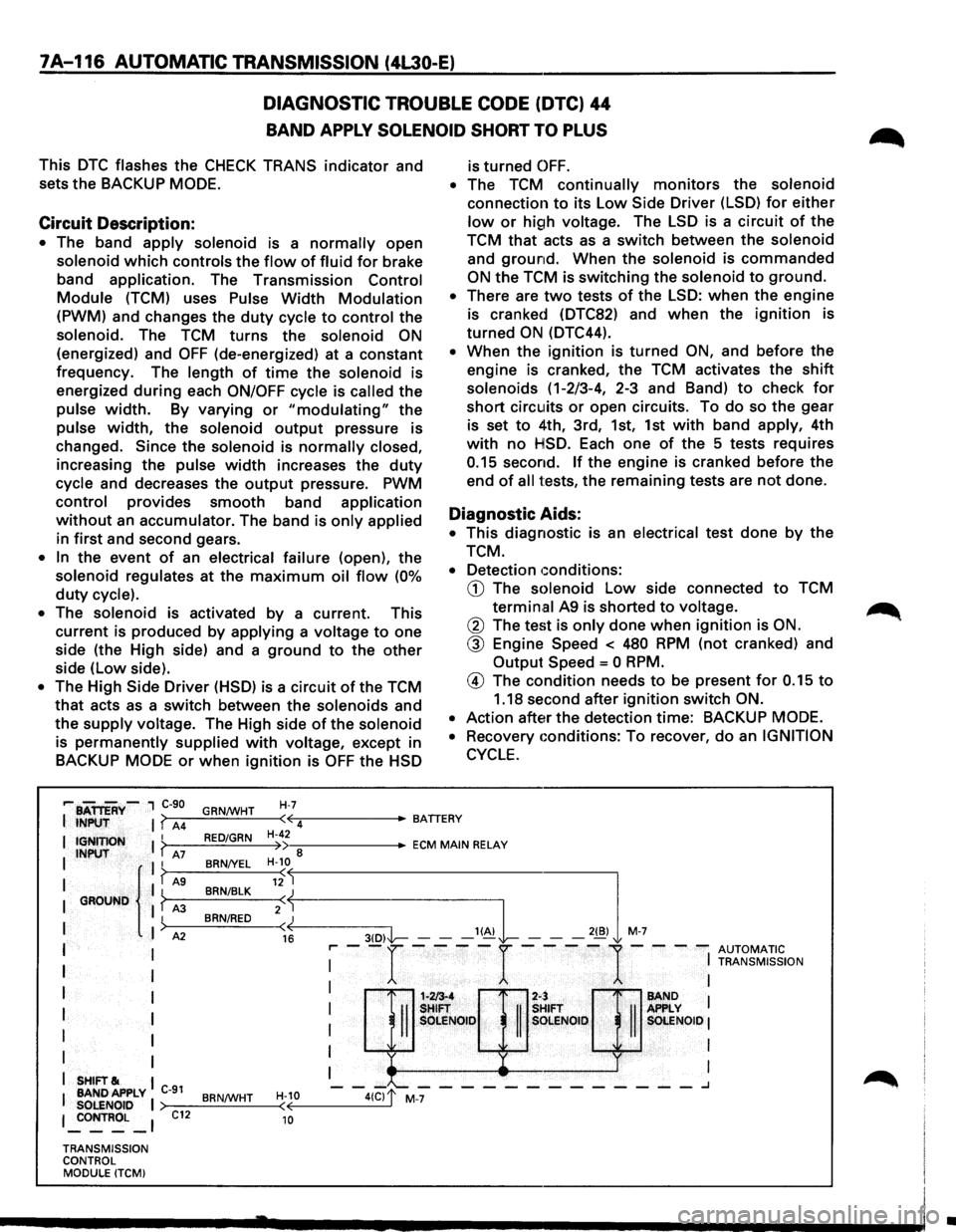
7A-116 AUTOMATIC TRANSMISSION (4L30-E)
DIAGNOSTIC TROUBLE CODE (DTC) 44
BAND APPLY SOLENOID SHORT TO PLUS
This DTC flashes the CHECK TRANS indicator and
sets the BACKUP
MODE.
Circuit Description:
• The band apply solenoid is a normally open
solenoid which controls the flow of fluid for brake
band
application. The Transmission Control
Module (TCM) uses Pulse Width Modulation
(PWM) and changes the duty cycle to control the
solenoid. The TCM turns the solenoid ON
(energized) and OFF (de-energized) at a constant
frequency. The
length of time the solenoid is
energized
during each ON/OFF cycle is called the
pulse width. By varying or "modulating" the
pulse width, the solenoid output pressure is
changed.
Since the solenoid is normally closed,
increasing the pulse width increases the duty
cycle and decreases the output pressure. PWM
control provides smooth band application
without an accumulator. The band is only applied
in first and second gears.
• In the event of an electrical failure (open), the
solenoid regulates at the maximum oil flow (0%
duty cycle).
•
The solenoid is activated by a current. This
current is produced by
applying a voltage to one
side (the High side) and a
ground to the other
side (low side).
• The High Side Driver (HSD) is a circuit of the TCM
that acts as a switch between the solenoids and
the
supply voltage. The High side of the solenoid
is permanently supplied with voltage, except in
BACKUP
MODE or when ignition is OFF the HSD
H-7
is turned OFF.
• The TCM continually monitors the solenoid
connection to its Low Side Driver (LSD) for either
low or high voltage. The LSD is a circuit of the
TCM
that acts as a switch between the solenoid
and ground. When the solenoid is commanded
ON the TCM is switching the solenoid to ground.
• There are two tests of the LSD: when the engine
is cranked (DTC82) and
when the ignition is
turned
ON (DTC44).
• When the ignition is turned ON, and before the
engine is cranked, the TCM activates the
shift
solenoids (1-2/3-4, 2-3 and Band) to check for
short circuits or open circuits. To do so the gear
is set
to 4th, 3rd, 1st, 1st with band apply, 4th
with no HSD. Each one of the 5 tests requires
0.15 second. If the engine is cranked before the
end
of all tests, the remaining tests are not done.
Diagnostic Aids:
• This diagnostic is an electrical test done by the
TCM.
• Detection conditions:
CD The solenoid Low side connected to TCM
termin.al A9 is shorted to voltage.
@ The test is only done when ignition is ON.
@ Engine Speed < 480 RPM (not cranked) and
Output
Speed = 0 RPM.
@ The condition needs to be present for 0.15 to
1.18 second after ignition switch ON.
•
Action after the detection time: BACKUP MODE.
•
Recovery conditions: To recover, do an IGNITION
CYCLE.
,... BATTERY-, C-90
I INPUT I? A4 GRN/WHT ·~-----BATTERY
( 4
I IGNITION I ? I INPUT A7 II
I { I? AS I GROUND I ? A3
I
)
I A2
I I
I
I
I I
I I
I
I
I I
I SHIFT& I
I BANDAPPLY C-91 SOLENOID I 1 _:oNTROL _ 1
TRANSMISSION
CONTROL MODULE (TCMI
C12
RED/GRN
BRN/YEL
BRN/BLK
BRN/RED
BRN/WHT
H-42 •--::------ECM MAIN RELAY )) 8 H-10
«--------3-(D--,I'l----- --'~L -,,,l M-7
( 12
2:j
16 r-- -r ----r ----
1-- --
AUTOMATIC I
I TRANSMISSION
: H::Q]:;& : I OLE SOlENOID I
I I
I I
1-213-4 2-:
-II
SHIFT
II
s SOLE NOlO s
-"--------_______ .J
H-10 ( 10
•
Page 1196 of 1928
8-6 CHASSIS ELECTRICAL
SPLICING WIRE
1. Open the Harness
If the harness is taped, remove the tape. To avoid wire
insulation damage, use a sewing "seam ripper"
{available from sewing supply stores) to cut open the
harness.
If the harness has a black plastic conduit, simply pull
out the desired wire.
2. Cut the wire
Begin by cutting as little wire off the harness as
possible. You
may need the extra length of wire later
if you decide to cut more wire off to change the
location
of a splice. You may have to adjust splice
locations
to make certain that each splice is at least
1-1/2" {40 mm) away from other splices, harness
branches,
or connectors.
3. Strip the insulation
When replacing a wire, use a wire of the same size as
the original wire. Check the stripped wire for nicks or
cut stands. If the wire is damaged, repeat the proce
dure on a new section of wire. The two stripped wire
ends should be equal in length.
4. Crimp the Wires
Select the proper clip to secure the splice. To deter
mine the proper clip size for the wire being spliced,
follow the directions included with your clips. Select
the correct anvil on the crimper.
{On most crimpers
your choice is limited to either a small or large anvil.)
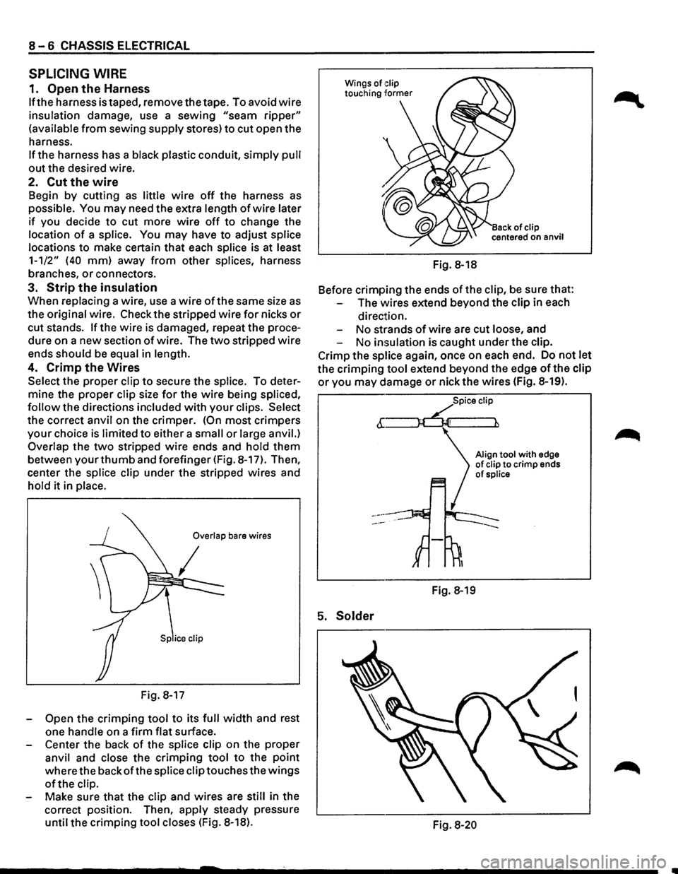
Overlap the two stripped wire ends and hold them
between your thumb and forefinger {Fig. 8-17). Then,
center the splice clip under
the stripped wires and
hold
it in place.
Overlap bare wires
Fig. 8-17
-
Open the crimping tool to its full width and rest
one handle on a
firm flat surface.
- Center
the back of the splice clip on the proper
anvil and close the
crimping tool to the point
where the backofthe splice clip touches the wings
of the clip.
Make sure
that the clip and wires are still in the
correct position. Then,
apply steady pressure
until
the crimping tool closes {Fig. 8-18). Fig.
8-18
Before
crimping the ends ofthe clip, be sure that:
The wires extend beyond
the clip in each
direction.
No strands of wire are cut loose, and
No insulation is caught under
the clip.
Crimp the splice again, once on each end. Do
not let
the crimping tool extend beyond the edge of the clip
or you may damage or nick the wires (Fig. 8-19).
5. Solder
Spice clip
6:~
Fig. 8-19
Align tool with edge of clip to crimp ends of splice
Fig. 8-20