width ISUZU TROOPER 1995 User Guide
[x] Cancel search | Manufacturer: ISUZU, Model Year: 1995, Model line: TROOPER, Model: ISUZU TROOPER 1995Pages: 1928
Page 617 of 1928
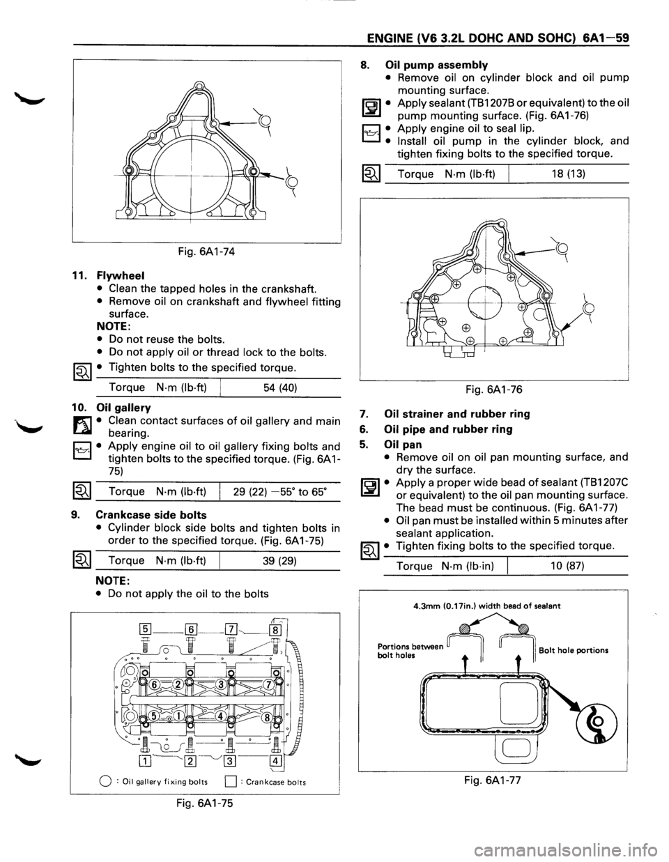
Fig. 6A1-74
11. Flywheel
• Clean the tapped holes in the crankshaft.
• Remove oil on crankshaft and flywheel fitting
surface.
NOTE:
• Do not reuse the bolts.
•
Do not apply oil or thread lock to the bolts.
~~~ • Tighten bolts to the specified torque.
Torque
N-m (lb·ft) 54 (40)
10. Oil gallery
m • Clean contact surfaces of oil gallery and main
~ bearing.
D • Apply engine oil to oil gallery fixing bolts and
L:::J tighten bolts to the specified torque. (Fig. 6A 1-
75)
~~~ Torque N·m (lb·ft) 29 (22) -55° to 65°
9. Crankcase side bolts
• Cylinder block side bolts and tighten bolts in
order
to the specified torque. (Fig. 6A 1-75)
~~~ Torque N·m (lb·ft) 39 (29)
NOTE:
• Do not apply the oil to the bolts
0 :Oil gallery fixing bolts 0: Crankcase bolts
Fig. 6A1-75
ENGINE (V6 3.2L DOHC AND SOHC) 6A1-59
8. Oil pump assembly
• Remove oil on cylinder block and oil pump
mounting surface.
ll:JI• Apply sealant (TB12078 or equivalent) to the oil
pump mounting surface. (Fig. 6A1-76)
19Y·I •. Apply engine oil to seal lip.
Install oil
pump in the cylinder block, and
tighten fixing
bolts to the specified torque.
1~1 Torque N·m (lb·ft)
Fig. 6A1-76
7. Oil strainer and rubber ring
6. Oil pipe and rubber ring
5. Oil pan
18 (13)
• Remove oil on oil pan mounting surface, and
dry the surface.
~~~· Apply a proper wide bead of sealant (TB1207C
or equivalent) to the oil pan mounting surface.
The bead
must be continuous. (Fig. 6A1-77)
• Oil pan must be installed within 5 minutes after
sealant application.
~~~· Tighten fixing bolts to the specified torque.
Torque
N·m (lb·in) 10 (87)
4.3mm (0.17in.) width bead of sealant
Portions between bolt holes I Bolt hole portions
D
Fig. 6A1-77
Page 644 of 1928
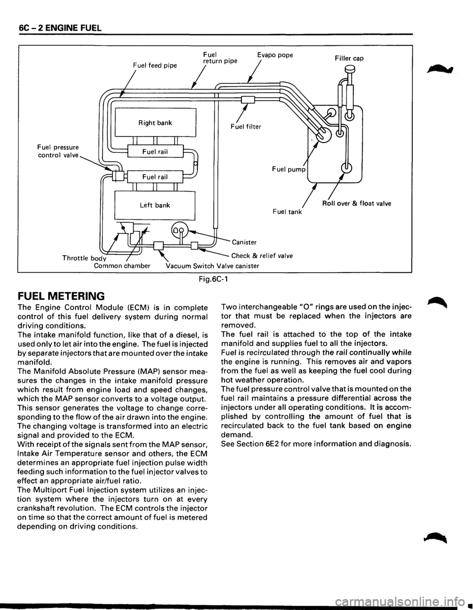
6C - 2 ENGINE FUEL
Fuel
Fuel
feed pipe return pipe Evapo pope
Fuel pressure
control valve Right
bank
Left bank Fuel tank
Canister
Throttle body Common chamber
Check & relief
valve
Vacuum Switch Valve canister
Fig.6C-1
FUEL METERING
The Engine Control Module (ECM) 1s 1n complete
control of this fuel delivery system during normal
driving conditions.
The intake manifold function, like that of a diesel, is
used
only to let air into the engine. The fuel is injected
by separate injectors that are mounted over the intake
manifold.
The Manifold Absolute Pressure (MAP) sensor mea
sures
the changes in the intake manifold pressure
which result from engine load and speed changes,
which the MAP sensor converts to a voltage output.
This sensor generates the voltage to change corre
sponding to the flow ofthe air drawn into the engine.
The
changing voltage is transformed into an electric
signal and provided to the ECM.
With receipt of the signals sent from the MAP sensor,
Intake Air Temperature sensor and others, the ECM
determines an appropriate fuel injection pulse width
feeding such information to the fuel injector valves to
effect an appropriate air/fuel ratio.
The
Multipart Fuel Injection system utilizes an injec
tion system where the injectors turn on at every
crankshaft revolution. The ECM controls the injector
on time so that the correct amount of fuel is metered
depending on driving conditions.
Two interchangeable "0" rings are used on the injec
tor that must be replaced when the injectors are
removed.
The fuel rail is attached to the top of the intake
manifold and supplies fuel to all the injectors.
Fuel is recirculated
through the rail continually while
the engine is running. This removes air and vapors
from the fuel as well as keeping the fuel cool during
hot weather operation.
The fuel pressure control valve that is mounted on the
fuel rail maintains a pressure differential across the
injectors under all operating conditions. It is accom
plished by controlling the amount of fuel that is
recirculated back
to the fuel tank based on engine
demand.
See Section 6E2 for more information and diagnosis.
;au
•
Page 698 of 1928
6E2-2 DRIVEABILITY AND EMISSIONS
DRIVEABILITV AND EMISSIONS GENERAL INFORMATION
CONTENTS
General Information
Driveability ....................... .
Emissions
........................ .
Maintenance
Schedule .............. .
Introduction ...................... .
Electronic Engine
Control .......... .
What This Section Contains ........ .
Blocking Drive Wheels
Visual/Physical
Underhood Inspection
6E2-3
6E2-3
6E2-3
6E2-3
6E2-3
6E2-3
6E2-3
6E2-3
Basic
Knowledge required . . . . . . . . . . . . 6E2-4
Basic Electric Circuits . . . . . . . . . . . . . .
6E2-4
Use
of Circuit Testing Tools . . . . . . . . . 6E2-4
Use
of Digital Volt-Ohm Meter (DVOM). 6E2-4
Diagnostic
Information . . . . . . . . . . . . . . . 6E2-4
"Check Engine" Malfunction Indicator
Lamp (MIL) . . . . . . . . . . . . . . . . . . . . 6E2-4
Intermittent "Check Engine"
Malfunction Indicator Lamp (MIL) . . 6E2-4
Reading Diagnostic
Trouble Codes . . . 6E2-5
Clearing
Trouble Codes . . . . . . . . . . . . 6E2-5
Diagnostic Test
Mode .............. 6E2-5
Engine Control
Module Learning
Ability . . . . . . . . . . . . . . . . . . . . . . . . 6E2-6
Field
Service Mode . . . . . . . . . . . . . . . . 6E2-6
Standard Nomenclature
for Certain
Electrical/Electronic
Components
and Systems . . . . . . . . . . . . . . . . . . . 6E2-6
Abbreviations and Glossary of Terms ..... 6E2-11
Driveability and Emissions
Section Summary ................... 6E2-12
Section .,. A"
Diagnostic Procedure Summary ...... 6E2-13
Data Link Connector
"SCAN Tools" ..... 6E2-14
Data
List (FO) ...................... 6E2-14
"SCAN Tool" Limitations and Use ...... 6E2-14
Intermittent Conditions ............ 6E2-14
"SCAN Tool" Positions ............... 6E2-14
Injector Pulse Width ............... 6E2-14
Closed Loop/Open Loop . . . . . . . . . . . .
6E2-14
Trouble Codes ................... 6E2-14
Throttle Position (TP) Sensor . . . . . . . . 6E2-14
Throttle Angle . . . . . . . . . . . . . . . . . . . 6E2-15 Heated
Oxygen
Sensor (H02S)
Vehicle Speed Sensor (VSS) ....... .
Programmable Read Only Memory ID .
Revolution
Per Minute (RPM) ...... .
Mile Per Hour (MPH) ............. .
Engine
Coolant Temperature (ECT) .. .
Intake Air Temperature (IAT)
Sensor
...................... .
Manifold Absolute Pressure (MAP) .. .
Barometric Pressure (BARO) ....... .
Exhaust Gas Recirculation
(EGR)
(ON/OFF) .................... .
Short Term (S.T.) Fuel Trim and
Long Term
(LT.) Fuel Trim ...... .
Long Term
(LT.) Fuel Trim ........ .
Idle Air Control (lAC) Counts ....... .
Desired Revolution
Per Minute ..... .
Air Conditioning (A/C) Request ..... .
Air Conditioning (A/C) Clutch ...... .
Power Steering Pressure (PSP)
Switch ...................... .
Battery Positive Voltage .......... .
Spark Advance .................. .
Start Up Engine Coolant .......... .
Engine
Speed (RPM) ............. .
Fuel Trim Enable ................ .
Air/Fuel Ratio .................. .
Induction Air Control ............. .
Section B -Driveability Symptoms ... .
Section C -Component Systems .... .
Engine
Control Module (ECM)
and
Sensors .................. .
Fuel Control System ............. .
Electric
Fuel Pump (in-tank) ....... .
Evaporative Emission
(EVAP)
Control System ................ .
Ignition Control (IC) .............. .
Exhaust Gas Recirculator
(EGR) .... .
Air Conditioning (A/C) Clutch Control .
Positive Crankcase Ventilation (PCV) .
Tools Needed
to Service the System .... .
General Specifications
............... .
Vacuum Hose Routing Diagram
........ .
6E2-15
6E2-15
6E2-15
6E2-15
6E2-15
6E2-15
6E2-15
6E2-15
6E2-15
6E2-15
6E2-15
6E2-16
6E2-16
6E2-16
6E2-16
6E2-16
6E2-16
6E2-16
6E2-16
6E2-16
6E2-16
6E2-16
6E2-16
6E2-16
6E2-16
6E2-16
6E2-17
6E2-17
6E2-17
6E2-17
6E2-17
6E2-17
6E2-17
6E2-17
6E2-18
6E2-21
6E2-22
~
... ...
•
Page 706 of 1928
6E2-10 DRIVEABILITY AND EMISSIONS
Former ISUZU Name New ISUZU Name Term
MPFI Injector Multiport Fuel Injection Injector -MFI Injection
MPH Mile Par Hour -MPH
Multi-Port Injection
Multiport Fuel Injection -MFI
02 Oxygen-02
02 Sensor Oxygen Sensor -02S
OBD On-Board Diagnostic -OBD
Oxygen Sensor
Heated Oxygen Sensor -H02S
Oxygen
Sensor Exhaust Oxygen Sensor -02S
P/N
Park/Neutral Position -PNP
Park/Neutral
Park/Neutral Position -PNP
Park/Neutral Switch Park/Neutral Position Switch -PNP Switch
PFI Multiport Fuel Injection -MFI
Port Fuel Injection Multiport Fuel Injection -MFI
Pressure Regulator
Fuel Pressure Control Valve
PROM Programmable Read Only Memory -PROM
PSPS Power Steering Pressure Switch-PSP Switch
Pulse Air Pulsed Secondary Air Injection -PAIR
Pulse Air Injection System Pulsed Secondary Air Injection System -PAIR System
Pulse Air System Pulsed Secondary Air Injection System -PAIR System
Pulse Width Modulate Pulse Width Modulate -PWM
PWM Pulse
Width Modulate -PWM
Rich Exhaust
Rich Heated Oxygen Sensor Signal -Rich H02S Signal
Rich Exhaust
Rich Oxygen Sensor Signal -Rich 02S Signal
Rich Mixture Signal Rich Heated Oxygen Sensor Signal -Rich H02S Signal
Rich Mixture Signal Rich Oxygen Sensor Signal -Rich 02S Signal
RPM Revolution Per Minute -RPM
SCAN
Scan Tool -ST
Scan Data Scan Tool Data -ST Data
Secondary
Air System Secondary Air Injection System -AIR System
Secondary
Air Valves Secondary Air Injection System Valves -AIR System Valve
Secondary Throttle Plate
Induction Air Control Plate System -lAC Plate System
Secondary Throttle
Plate System Induction Air Control Plate System -lAC Plate System
System Too Lean
Lean Heated
Oxygen Sensor Signal -Lean H02S Signal
System Too Rich
Rich Heated Oxygen Sensor Signal -Rich H02S Signal
System Voltage Battery Positive Voltage -B+
TB Throttle Body -TB
TBI Throttle Body Fuel Injection -TBI
Temperature Gauge
Engine Coolant Temperature Gause -ECT Gauge
Thermal Vacuum Switch
Thermal Vacuum
Valve -TVV
Thermal Vacuum Valve Thermal Vacuum Valve -TVV
Thermostatic Air Cleaner Air Cleaner -ACL
Page 708 of 1928
6E2-12 DRIVEABILITY AND EMISSIONS
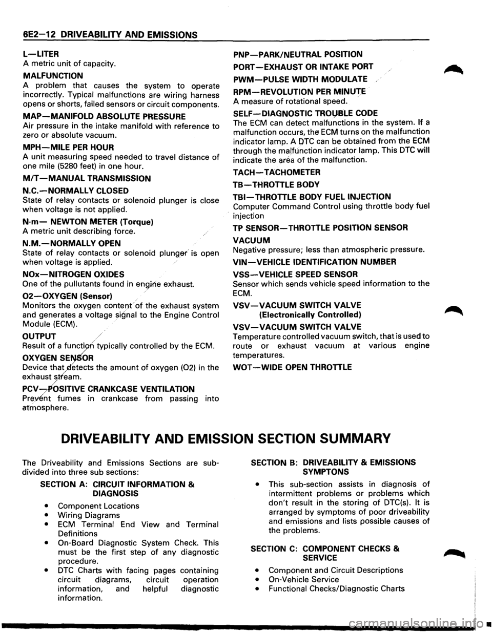
L-LITER
A metric unit of capacity.
MALFUNCTION
A problem that causes the system to operate
incorrectly. Typical malfunctions are wiring harness
opens
or shorts, failed sensors or circuit components.
MAP-MANIFOLD ABSOLUTE PRESSURE
Air pressure in the intake manifold with reference to
zero or absolute vacuum.
MPH-MILE PER HOUR
A unit measuring speed needed to travel distance of
one mile (5280 feet) in one hour.
MIT -MANUAL TRANSMISSION
N.C.-NORMALLY CLOSED
State of relay contacts or solenoid plunger is close
when voltage is not applied.
N·m-NEWTON METER (Torque)
A metric unit describing force.
N.M.-NORMALLY OPEN
State of relay contacts or solenoid plung&r' is open
when voltage is applied.
NOx-NITROGEN OXIDES
One of the pullutants found in engirie exhaust.
02-0XYGEN (Sensor)
Monitors the oxygen contel)f of the exhaust system
and generates a
voltage signal to the Engine Control
Module (ECM).
OUTPUT
Result of a functi typically controlled by the ECM.
OXYGEN SE OR
Device that etects the amount of oxygen (02) in the
exhaust
stfeam. /
PCV-~OSITIVE CRANKCASE VENTILATION
Prey£nt fumes in crankcase from passing into
atmosphere.
PNP-PARK/NEUTRAL POSITION
PORT-EXHAUST OR INTAKE PORT
PWM-PULSE WIDTH MODULATE
RPM-REVOLUTION PER MINUTE
A measure of rotational speed.
SELF-DIAGNOSTIC TROl)SLE CODE
The ECM can detect malfunctions in the system. If a
malfunction occurs, the ECM turns on the malfunction
indicator lamp. A OTC can be obtained from the ECM
through the malfunction indicator lamp. This DTC will
indicate the area of the malfunction.
TACH-TACHOMETER
TB-THROTTLE BODY
TBI-THROTTLE BODY FUEL INJECTION
Computer Command Control using throttle body fuel
injection
TP SENSOR-THROTTLE POSITION SENSOR
VACUUM
Negative pressure; less than atmospheric pressure.
VIN-VEHICLE IDENTIFICATION NUMBER
VSS-VEHICLE SPEED SENSOR
Sensor which sends vehicle speed information to the
ECM.
VSV-VACUUM SWITCH VALVE
(Electronically Controlled)
VSV-VACUUM SWITCH VALVE
Temperature controlled vacuum switch, that is used to
route or exhaust vacuum at various engine
temperatures.
WOT -WIDE OPEN THROTTLE
DRIVEABILITV AND EMISSION SECTION SUMMARY
The Driveability and Emissions Sections are sub
divided into three sub sections:
SECTION A: CIRCUIT INFORMATION &
DIAGNOSIS
• Component Locations
• Wiring Diagrams
• ECM Terminal End View and Terminal
Definitions
• On-Board Diagnostic System Check. This
must be the first step of any diagnostic
procedure.
• DTC Charts with facing pages containing
circuit diagrams, circuit operation
information, and
helpful diagnostic
information.
SECTION B: DRIVEABILITY & EMISSIONS
SYMPTONS
• This sub-section assists in diagnosis of
intermittent problems or problems which
don't result in the storing of DTC(s). It is
arranged
by symptoms of poor driveability
and emissions and lists possible causes of
the problems.
SECTION C: COMPONENT CHECKS &
SERVICE
• Component and Circuit Descriptions
• On-Vehicle Service
• Functional
Checks/Diagnostic Charts
•
Page 710 of 1928
6E2-14 DRIVEABILITY AND EMISSIONS
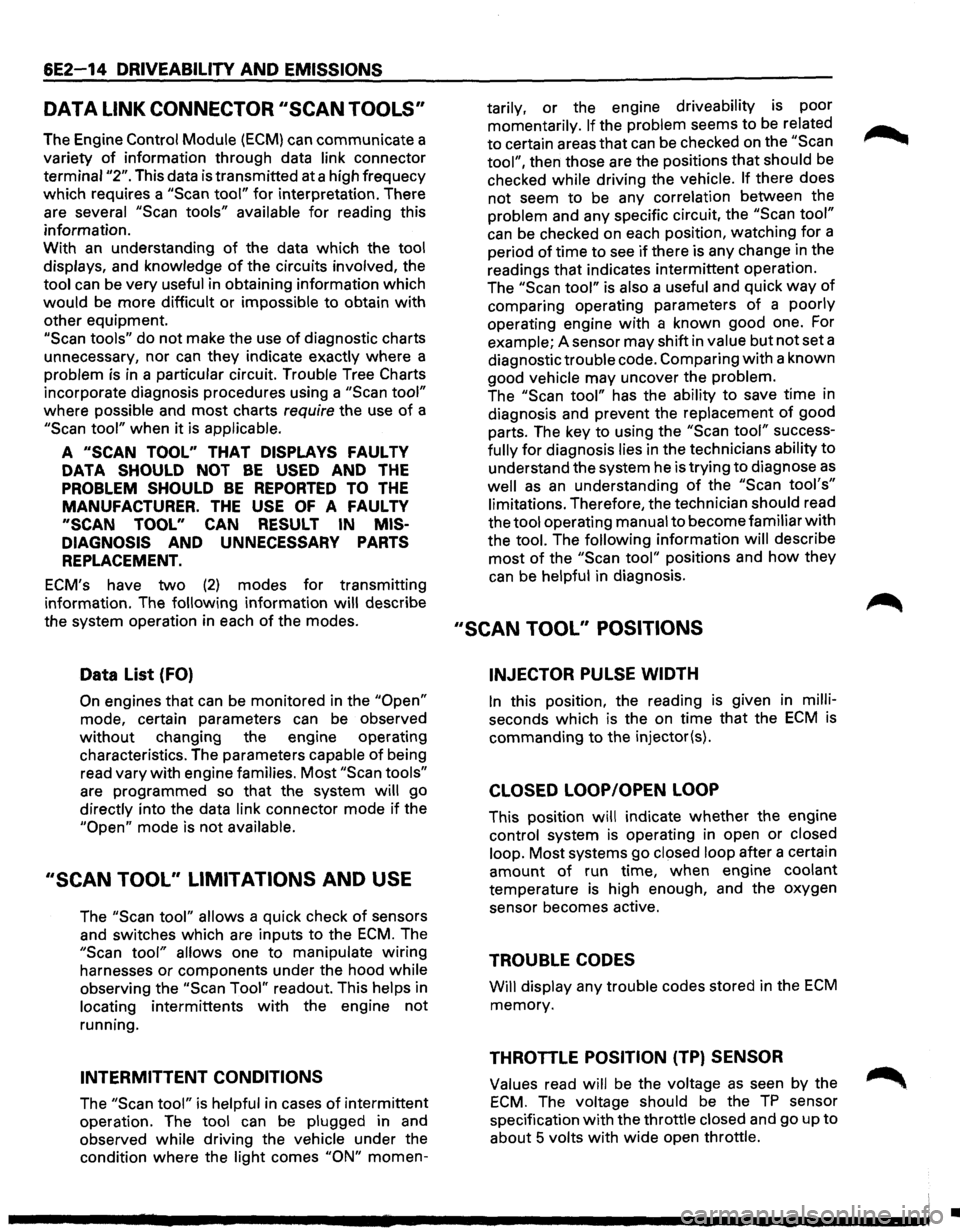
DATA LINK CONNECTOR ''SCAN TOOLS''
The Engine Control Module (ECM) can communicate a
variety
of information through data link connector
terminal
"2". This data is transmitted at a high frequecy
which requires a
"Scan tool" for interpretation. There
are several
"Scan tools" available for reading this
information.
With an understanding
of the data which the tool
displays, and knowledge of the circuits involved, the
tool can be
very useful in obtaining information which
would be more difficult or impossible to obtain with
other equipment.
"Scan tools" do not make the use of diagnostic charts
unnecessary, nor
can they indicate exactly where a
problem is in a particular circuit. Trouble Tree
Charts
incorporate diagnosis procedures using a "Scan tool"
where possible and most charts require the use of a
"Scan tool" when it is applicable.
A "SCAN TOOL" THAT DISPLAYS FAUL TV
DATA SHOULD NOT BE USED AND THE
PROBLEM SHOULD BE REPORTED TO THE
MANUFACTURER. THE USE OF A FAUL TV
"SCAN TOOL" CAN RESULT IN MIS
DIAGNOSIS
AND UNNECESSARY PARTS
REPLACEMENT.
ECM's have two (2) modes for transmitting
information. The
following information will describe
the system operation in each
of the modes.
Data List (FO)
On engines that can be monitored in the "Open"
mode, certain parameters can be observed
without changing the engine operating
characteristics. The parameters capable
of being
read vary with engine families.
Most "Scan tools"
are programmed so that the system will go
directly into the data link connector mode
if the
"Open" mode is not available.
''SCAN TOOL'' LIMITATIONS AND USE
The "Scan tool" allows a quick check of sensors
and switches which are inputs
to the ECM. The
"Scan tool" allows one to manipulate wiring
harnesses or components under the hood while
observing the "Scan Tool" readout. This helps in
locating intermittents
with the engine not
running.
INTERMITTENT CONDITIONS
The "Scan tool" is helpful in cases of intermittent
operation. The
tool can be plugged in and
observed while driving the vehicle under the
condition
where the light comes "ON" momen- tarily,
or the
engine driveability is poor
momentarily.
If the problem seems to be related
to certain areas
that can be checked on the "Scan ~
tool", then those are the positions that should be
checked while driving the vehicle. If there does
not seem to
be any correlation between the
problem and any specific circuit, the
"Scan tool"
can be checked on each position, watching for a
period
of time to see if there is any change in the
readings that indicates intermittent operation.
The
"Scan tool" is also a useful and quick way of
comparing operating parameters of a poorly
operating engine with a known good one. For
example; A sensor may shift in
value but not set a
diagnostic trouble code. Comparing with a known
good vehicle may uncover the problem.
The
"Scan tool" has the ability to save time in
diagnosis and prevent the replacement
of good
parts. The key to using the
"Scan tool" success
fully
for diagnosis lies in the technicians ability to
understand the system he is trying to diagnose as
well as an understanding of the "Scan tool's"
limitations. Therefore, the technician should read
the tool operating manual to become familiar
with
the tool. The following information will describe
most of the "Scan tool" positions and how they
can be helpful in diagnosis.
"SCAN TOOL" POSITIONS
INJECTOR PULSE WIDTH
In this position, the reading is given in milli
seconds which is the on time that the ECM is
commanding to the injector(s).
CLOSED LOOP/OPEN LOOP
This position will indicate whether the engine
control system
is operating in open or closed
loop. Most systems go closed loop after a certain
amount of run time, when engine coolant
temperature
is high enough, and the oxygen
sensor becomes active.
TROUBLE CODES
Will display any trouble codes stored in the ECM
memory.
THROTTLE POSITION (TP) SENSOR
Values read will be the voltage as seen by the ~
ECM. The voltage should be the TP sensor
specification
with the throttle closed and go up to
about 5 volts with
wide open throttle.
•
Page 730 of 1928
6E2-34 DRIVEABILITY AND EMISSIONS
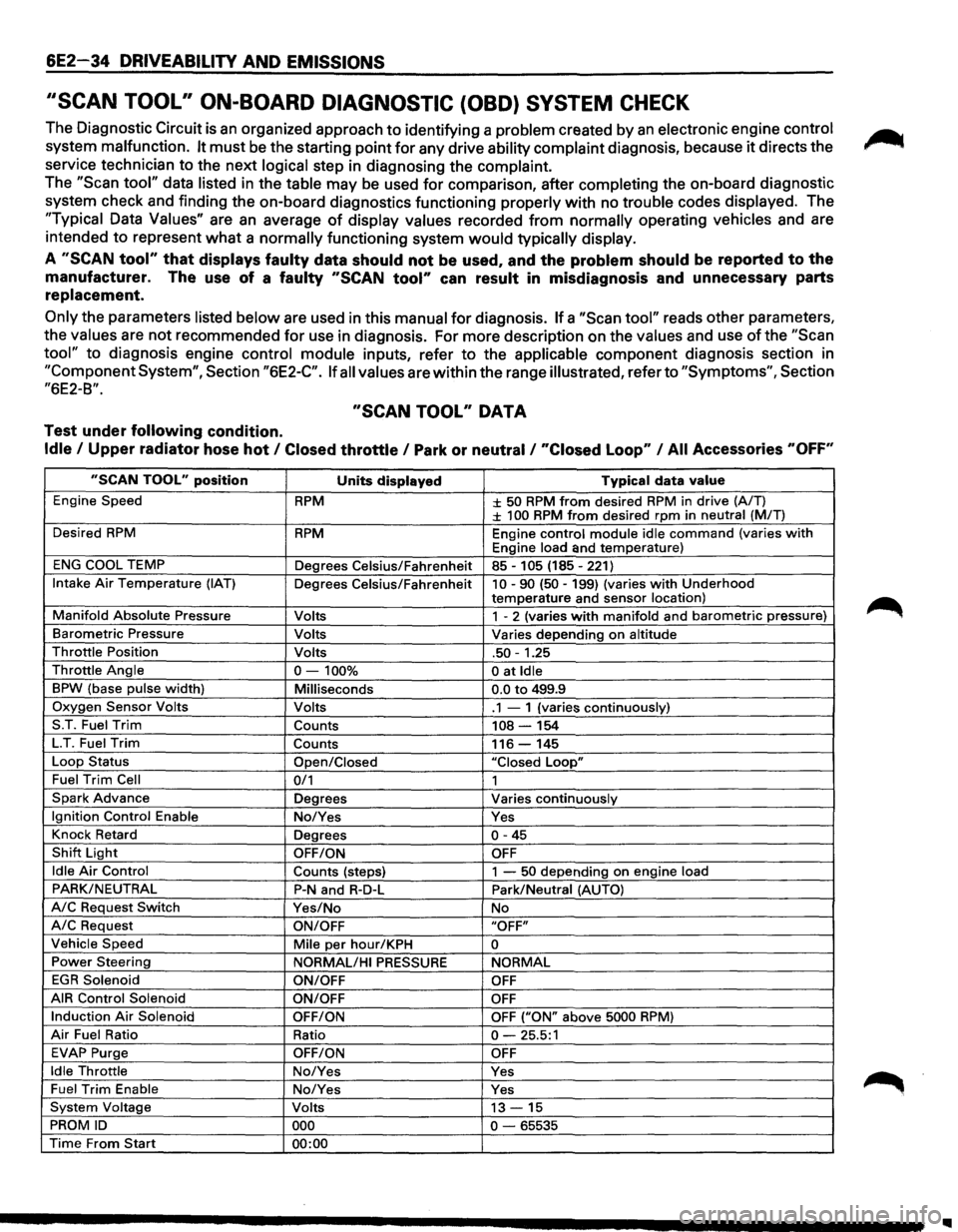
''SCAN TOOL" ON-BOARD DIAGNOSTIC (OBD) SYSTEM CHECK
The Diagnostic Circuit is an organized approach to identifying a problem created by an electronic engine control
system malfunction. It must be the starting point for any drive ability complaint diagnosis, because it directs the
service technician to the next
logical step in diagnosing the complaint.
The "Scan tool" data listed in the table may be used for comparison, after completing the on-board diagnostic
system check and finding the on-board diagnostics functioning
properly with no trouble codes displayed. The
"Typical Data Values" are an average of display values recorded from normally operating vehicles and are
intended
to represent what a normally functioning system would typically display.
A "SCAN tool" that displays faulty data should not be used, and the problem should be reported to the
manufacturer. The use of a faulty "SCAN tool" can result in misdiagnosis and unnecessary parts
replacement.
Only the parameters listed below are used in this manual for diagnosis. If a "Scan tool" reads other parameters,
the
values are not recommended for use in diagnosis. For more description on the values and use of the "Scan
tool" to diagnosis engine control module inputs, refer to the applicable component diagnosis section in
"Component System", Section "6E2-C". If all values are within the range illustrated, refer to "Symptoms", Section
"6E2-B".
"SCAN TOOL" DATA
Test under following condition.
Idle I Upper radiator hose hot I Closed throttle I Park or neutral I "Closed Loop" I All Accessories "OFF"
"SCAN TOOL" position Units displayed Typical data value
Engine Speed RPM ± 50 RPM from desired RPM in drive (A/T) ± 100 RPM from desired rpm in neutral (MIT)
Desired
RPM RPM Engine control module idle command (varies with Engine load and temperature)
ENG COOL TEMP
Degrees Celsius/Fahrenheit 85-105 (185-221)
Intake Air Temperature (IAT) Degrees Celsius/Fahrenheit 10-90 (50-199) (varies with Underhood
temperature and sensor location)
Manifold Absolute Pressure Volts 1 - 2 (varies with manifold and barometric pressure)
Barometric Pressure Volts Varies depending on altitude
Throttle Position Volts .50-1.25
Throttle Angle 0-100% 0 at Idle
BPW (base pulse width) Milliseconds 0.0 to 499.9
Oxygen Sensor Volts Volts .1 - 1 (varies continuously)
S.T. Fuel
Trim Counts 108-154
LT. Fuel Trim Counts 116-145
Loop Status
Open/Closed "Closed Loop"
Fuel Trim Cell 0/1 1
Spark Advance Degrees Varies continuously
Ignition Control Enable No/Yes Yes
Knock Retard
Degrees
0-45
Shift Light OFF/ON OFF
Idle Air Control
Counts (steps) 1 -50 depending on engine load
PARK/NEUTRAL P-N and R-D-L Park/Neutral (AUTO)
A/C Request Switch Yes/No No
A/C Request ON/OFF "OFF"
Vehicle Speed
Mile per hour/KPH 0
Power Steering
NORMAL/HI PRESSURE NORMAL
EGR Solenoid
ON/OFF OFF
AIR Control Solenoid
ON/OFF OFF
Induction Air Solenoid OFF/ON OFF ("ON" above 5000 RPM)
Air Fuel Ratio Ratio 0-25.5:1
EVAP Purge OFF/ON OFF
Idle Throttle No/Yes Yes
Fuel Trim Enable No/Yes Yes
System Voltage Volts 13-15
PROM ID 000 0-65535
Time From Start 00:00
Page 813 of 1928
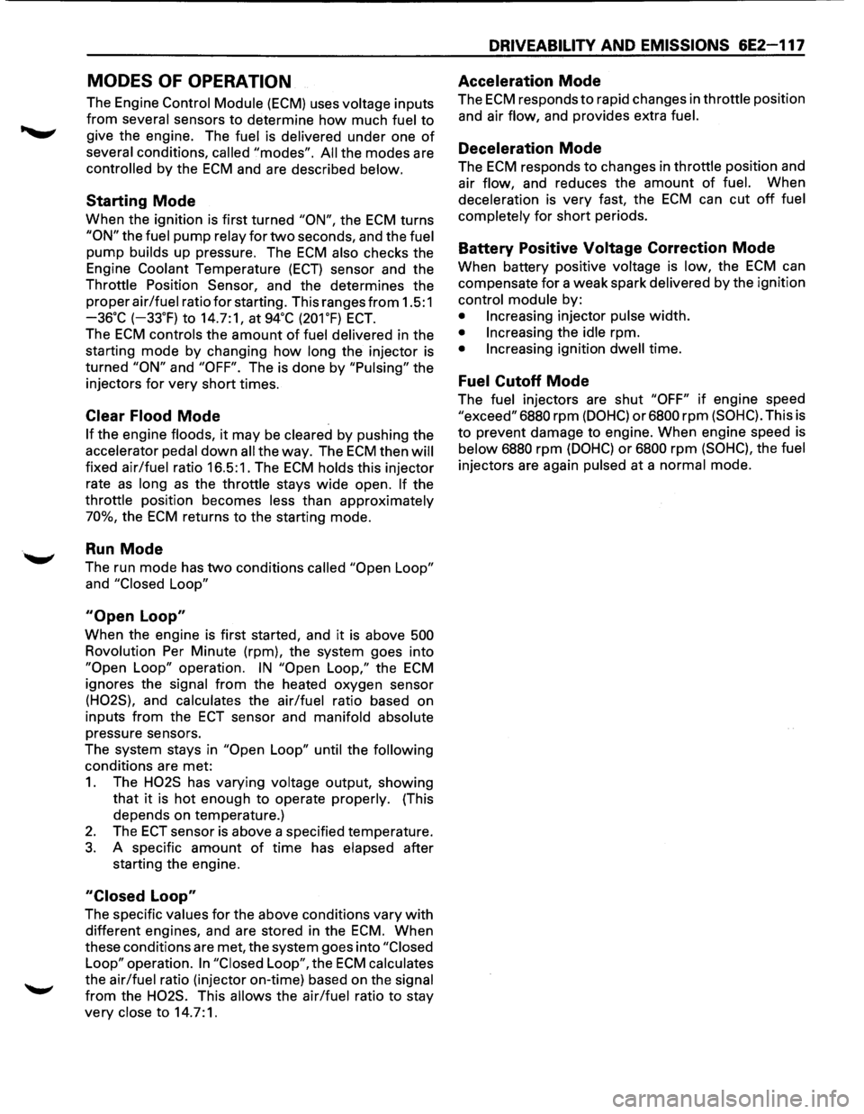
MODES OF OPERATION
The Engine Control Module (ECM) uses voltage inputs
from several sensors to determine how much fuel to
give the engine. The fuel is delivered under one of
several conditions, called "modes". All the modes are
controlled by the ECM and are described below.
Starting Mode
When the ignition is first turned "ON", the ECM turns
"ON" the fuel pump relay for two seconds, and the fuel
pump builds up pressure. The ECM also checks the
Engine
Coolant Temperature (ECT) sensor and the
Throttle Position Sensor, and the determines the
proper
air/fuel ratio for starting. This ranges from 1.5:1
-36·c (-33.F) to 14.7:1, at 94•c (201.F) ECT.
The ECM controls the amount of fuel delivered in the
starting mode by changing
how long the injector is
turned
"ON" and "OFF". The is done by "Pulsing" the
injectors
for very short times.
Clear Flood Mode
If the engine floods, it may be cleared by pushing the
accelerator pedal down all the way. The ECM then will
fixed air/fuel ratio 16.5:1. The ECM holds this injector
rate
as long as the throttle stays wide open. If the
throttle position becomes less than approximately
70%, the ECM returns to the starting mode.
Run Mode
The run mode has two conditions called "Open Loop"
and "Closed Loop"
"Open Loop"
When the engine is first started, and it is above 500
Rovolution Per Minute (rpm), the system goes into
"Open Loop" operation. IN "Open Loop," the ECM
ignores the signal from the heated oxygen sensor
(H02S), and calculates the air/fuel ratio based on
inputs
from the ECT sensor and manifold absolute
pressure sensors.
The system stays in
"Open Loop" until the following
conditions are met:
1. The H02S has varying voltage output, showing
that
it is hot enough to operate properly. (This
depends on temperature.)
2. The ECT sensor is above a specified temperature.
3. A specific amount of time has elapsed after
starting the engine.
"Closed Loop"
The specific values for the above conditions vary with
different engines, and are stored in the ECM. When
these conditions are met, the system goes into
"Closed
Loop"
operation. In "Closed Loop", the ECM calculates
the air/fuel ratio (injector on-time) based on the signal
from the H02S. This allows the air/fuel ratio to stay
very close to 14.7:1.
DRIVEABILITV AND EMISSIONS 6E2-117
Acceleration Mode
The ECM responds to rapid changes in throttle position
and air
flow, and provides extra fuel.
Deceleration Mode
The ECM responds to changes in throttle position and
air
flow, and reduces the amount of fuel. When
deceleration is very fast, the ECM can cut off fuel
completely
for short periods.
Battery Positive Voltage Correction Mode
When battery positive voltage is low, the ECM can
compensate
for a weak spark delivered by the ignition
control module by:
• Increasing injector pulse width.
• Increasing the idle rpm.
• Increasing ignition dwell time.
Fuel Cutoff Mode
The fuel injectors are shut "OFF" if engine speed
"exceed" 6880 rpm (DOHC) or6800 rpm (SOHC). This is
to prevent damage to engine. When engine speed is
below 6880 rpm (DOHC) or 6800 rpm (SOHC), the fuel
injectors are again pulsed at a normal mode.
Page 815 of 1928
FUEL INJECTORS
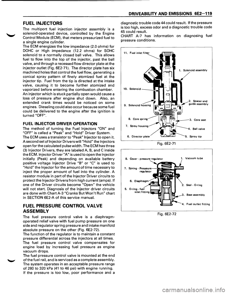
The multipart fuel injection injector assembly is a
solenoid-operated device, controlled
by the Engine
Control Module (ECM), that meters pressurized fuel to
a single engine cylinder.
The
ECM energizes the low impedance (2.0 ohms) for
DOHC or High impedance (12.2 ohms) for SOHC
solenoid to a normally closed ball valve. This allows
fuel
to flow into the top of the injector, past the ball
valve, and through a recessed
flow director plate at the
injector outlet (Fig. 6E2-71). The director plate has six
machined holes
that control the fuel flow, generating a
conical spray pattern
of finely atomized fuel at the
injector tip. Fuel
from the tip is directed at the intake
valve, causing
it to become further atomized and
vaporized before entering the combustion chamber.
An injector which is stuck partially open
would cause a
loss
of pressure after engine shut down. Also, an
extended crank times would be noticed on some
engines. Dieseling could also
occ!Jr because some fuel
could be delivered
to the engine after the ignition is
turned
"OFF".
FUEL INJECTOR DRIVER OPERATION
The method of turning the Fuel Injectors "ON" and
"OFF" is called a "Peak" and "Hold" Driver System.
The
ECM uses a transistor to "Peak" Injector to open it.
A second set
of Injector Drivers will "Hold" the Injectors
open for the calculated pulse width. The ECM has three
(3) Injector Drivers, they are labeled A, 8, and C inside
the
ECM. Injector Driver "A" is used to open the Injector
initially (Peak) and depending on available battery
positive voltage
Injector Drive "8" or "C" is used to
"Hold" the Injector for the amount of time necessary to
inject the proper amount of fuel into the cylinder. A
resistor module in part
of the Injector Driver circuits to
protect the Injector Drivers from high current (amps). If
one of the Driver circuits become "Open" the vehicle
will
not start. Diagnosis of the Injector driver circuits
are done
with Chart A-3 "Cranks But Won't Run" chart
in
SECTION 6E2-A of this service manual.
FUEL PRESSURE CONTROL VALVE
ASSEMBLY
The fuel pressure control valve is a diaphragm
operated relief valve
with fuel pump pressure on one
side and regulator spring pressure and intake manifold
absolute pressure on the other (Fig. 6E2-72).
The function
of the regulator is to maintain a constant
pressure differential across the injectors at all times.
The fuel pressure control valve compensates
for
engine load by increasing fuel pressure as engine
vacuum drops.
The fuel pressure control valve is mounted at the end
ofthe fuel rail, and is serviced as a complete assembly.
The system operates in
an acceptable pressure range
of 280 to 320 kPa (41 to 46 psi) with engine running.
If the pressure is too low, poor performance and a
DRIVEABILITV AND EMISSIONS 6E2-119
diagnostic trouble code 44 could result. If the pressure
is too high, excess odor and a diagnostic trouble code
45 could result.
CHART A-7 has information on diagnosing fuel
pressure conditions.
11. Fuel inlet
Fig. 6E2-71
1. Solenoid assembly
Spacer
and
guide assembly
. Ball valve
8. Cover-pressure regulator 1. Vacuum tube
7.
6.
Seal · 0-ring
Base assembly
Fuel
outlet fitting
Fig. 6E2-72
Page 817 of 1928
Throttle Position (TP) Sensor
The Throttle Position (TP) Sensor is mounted on the
side
of the throttle body opposite the throttle lever
assembly.
Its function is to sense the current throttle
body position and relay that information to the ECM.
Knowledge ofTP is needed by the ECM to generate the
proper injector pulse width.
If the TP sensor senses a
Wide
Open Throttle, a voltage signal indicating this
condition is transmitted to the
ECM. The ECM will
widen the injector pulse, or increase the repetition rate,
permitting increased fuel
flow to each for the six fuel
injectors located in the fuel fail. As the throttle shaft
rotates in response to
movement of the accelerator
pedal (opening
or closing of the throttle body), the
throttle shaft transmits throttle
movement to the TP
sensor. A potentiometer (variable resistor) within the
TP sensor assembly creates a voltage that varies in
response to
TP. By applying a reference voltage (+5
VDC) to the TP sensor input, a varying voltage
(reflecting
TP) is available at the TP sensor output. The
voltage
output from the TP sensor is sent to the ECM
for use in determining current TP.
For further information ofTP sensor, refer to "ECM and
Sensors", Section
"6E2-C1 ". The TP sensor is an auto
zeroing type and cannot
be adjusted.
DRIVEABILITY AND EMISSIONS 6E2-121
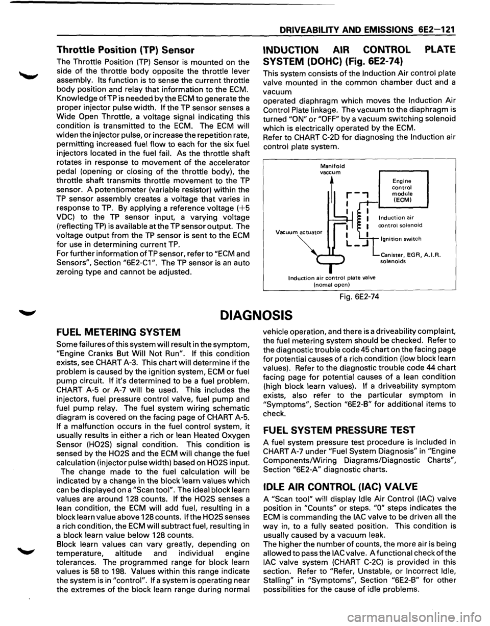
INDUCTION AIR CONTROL PLATE
SYSTEM (DOHC) (Fig. 6E2-74)
This system consists of the Induction Air control plate
valve mounted in the common chamber
duct and a
vacuum operated diaphragm
which moves the Induction Air
Control Plate linkage. The vacuum to the diaphragm is
turned
"ON" or "OFF" by a vacuum switching solenoid
which is electrically operated by the
ECM.
Refer to CHART C-20 for diagnosing the Induction air
control plate system.
Manifold vaccum
1
Vacuum actuator
Induction air control plate valve
(noma! open)
Fig. 6E2-74
Engine control module (ECM)
Ignition switch
Canister, EGR, A.I.R. solenoids
DIAGNOSIS
FUEL METERING SYSTEM
Some failures of this system will result in the symptom,
"Engine Cranks But Will Not Run". If this condition
exists, see CHART A-3. This chart will determine
if the
problem is caused by the ignition system,
ECM or fuel
pump circuit.
If it's determined to be a fuel problem.
CHART A-5
or A-7 will be used. This includes the
injectors, fuel pressure control valve, fuel
pump and
fuel pump relay. The fuel system
wiring schematic
diagram is covered on the facing page
of CHART A-5.
If a malfunction occurs in the fuel control system, it
usually results in either a rich or lean Heated Oxygen
Sensor (H02S) signal condition. This condition is
sensed by the
H02S and the ECM will change the fuel
calculation (injector pulse width) based on
H02S input.
The change made to the fuel calculation will be
indicated
by a change in the block learn values which
can be displayed on a
"Scan tool". The ideal block learn
values are around 128 counts.
If the H02S senses a
lean condition, the
ECM will add fuel, resulting in a
block learn value above 128 counts.
If the H02S senses
a rich condition, the
ECM will subtract fuel, resulting in
a block learn value below 128 counts.
Block learn values can vary greatly, depending on
temperature, altitude and individual engine
tolerances. The programmed range for block learn
values is
58 to 198. Values within this range indicate
the system is in
"control". If a system is operating near
the extremes
of the block learn range during normal vehicle
operation, and there is a driveability complaint,
the fuel metering system should be checked. Refer to
the diagnostic trouble code
45 chart on the facing page
for potential causes of a rich condition (low block learn
values). Refer to the diagnostic trouble code 44 chart
facing page
for potential causes of a lean condition
(high block learn values).
If a driveability symptom
exists, also refer to the particular symptom in
"Symptoms", Section "6E2-B" for additional items to
check.
FUEL SYSTEM PRESSURE TEST
A fuel system pressure test procedure is included in
CHART A-7 under
"Fuel System Diagnosis" in "Engine
Components/Wiring Diagrams/Diagnostic
Charts",
Section "6E2-A" diagnostic charts.
IDLE AIR CONTROL (lAC) VALVE
A "Scan tool" will display Idle Air Control (lAC) valve
position in
"Counts" or steps. "0" steps indicates the
ECM is commanding the lAC valve to be driven all the
way in, to a fully seated position. This condition is
usually caused by a vacuum leak.
The higher the number
of counts, the more air is being
allowed to pass the
lAC valve. A functional check of the
lAC valve system (CHART C-2C) is provided in this
section. Refer to
"Refer, Unstable, or Incorrect Idle,
Stalling"
in "Symptoms", Section "6E2-B" for other
possibilities
for the cause of idle problems.