ISUZU TROOPER 1998 Service Repair Manual
TROOPER 1998
ISUZU
ISUZU
https://www.carmanualsonline.info/img/61/57184/w960_57184-0.png
ISUZU TROOPER 1998 Service Repair Manual
Trending: ECO mode, Coolant system, maintenance, fuel type, coolant temperature, oil filter, catalytic converter
Page 1701 of 3573
STARTING SYSTEM 6D2 Ð 7
INSPECTION AND REPAIR
Repair or replace necessary parts if extreme wear or
damage is found during inspection.
Armature
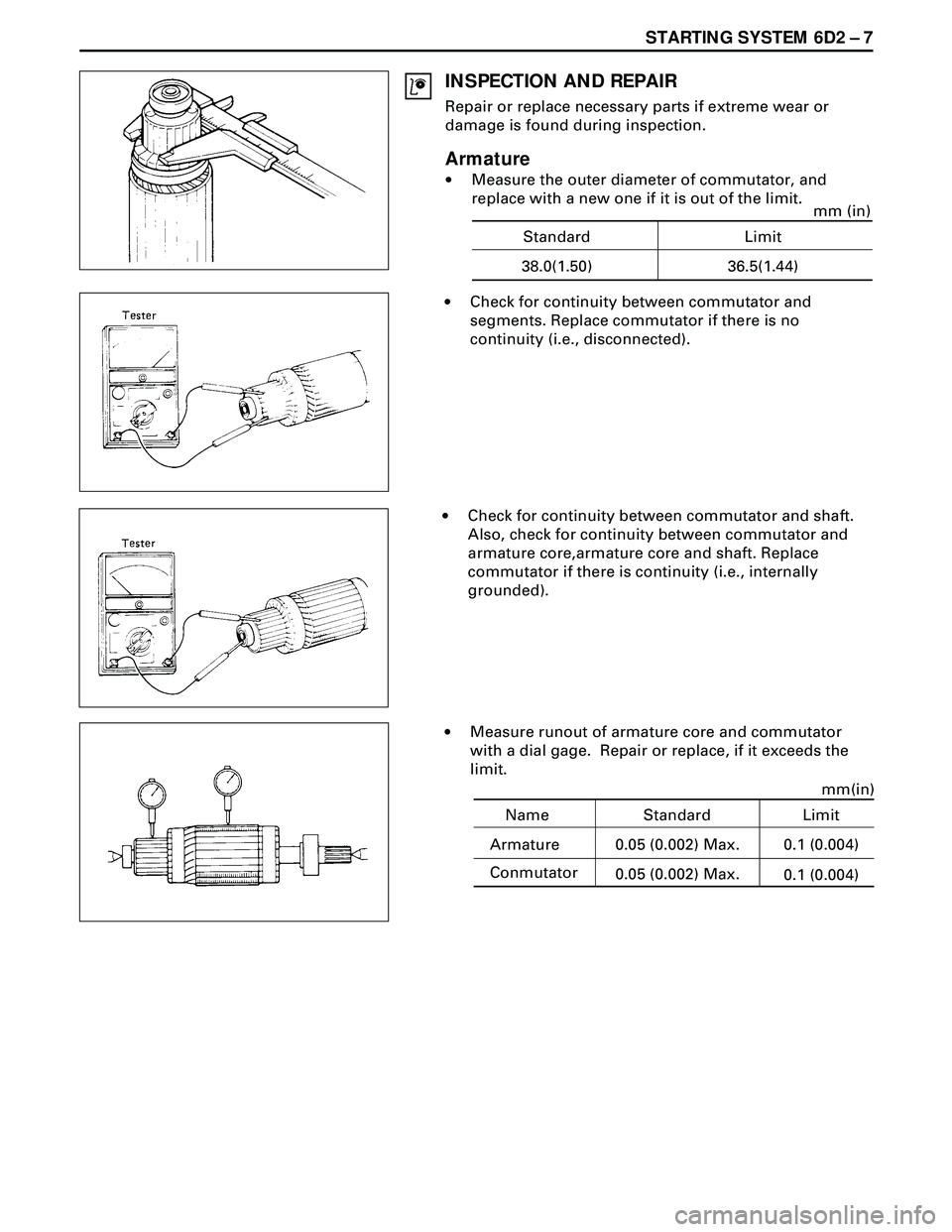
·Measure the outer diameter of commutator, and
replace with a new one if it is out of the limit.
·Check for continuity between commutator and
segments. Replace commutator if there is no
continuity (i.e., disconnected).
·Check for continuity between commutator and shaft.
Also, check for continuity between commutator and
armature core,armature core and shaft. Replace
commutator if there is continuity (i.e., internally
grounded).
·Measure runout of armature core and commutator
with a dial gage. Repair or replace, if it exceeds the
limit.
Name Standard
Armature 0.05 (0.002) Max.mm(in)
Conmutator
0.05 (0.002) Max.0.1 (0.004)
0.1 (0.004)
Limit
Standard Limit
38.0(1.50) 36.5(1.44)mm (in)
Page 1702 of 3573
6D2 Ð 8 STARTING SYSTEM
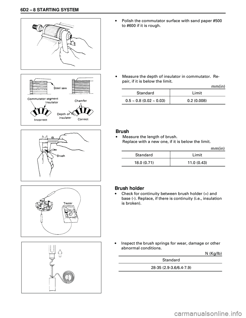
·Polish the commutator surface with sand paper #500
to #600 if it is rough.
·Measure the depth of insulator in commutator. Re-
pair, if it is below the limit.
Brush
·Measure the length of brush.
Replace with a new one, if it is below the limit.
Brush holder
·Check for continuity between brush holder (+) and
base (-). Replace, if there is continuity (i.e., insulation
is broken).
·Inspect the brush springs for wear, damage or other
abnormal conditions.
Standard Limit
0.5 ~ 0.8 (0.02 ~ 0.03) 0.2 (0.008)mm(in)
Standard Limit
18.0 (0.71) 11.0 (0.43)mm(in)
Standard
28-35 (2.9-3.6/6.4-7.9)N (Kg/lb)
Page 1703 of 3573
STARTING SYSTEM 6D2 Ð 9
Magnetic switch
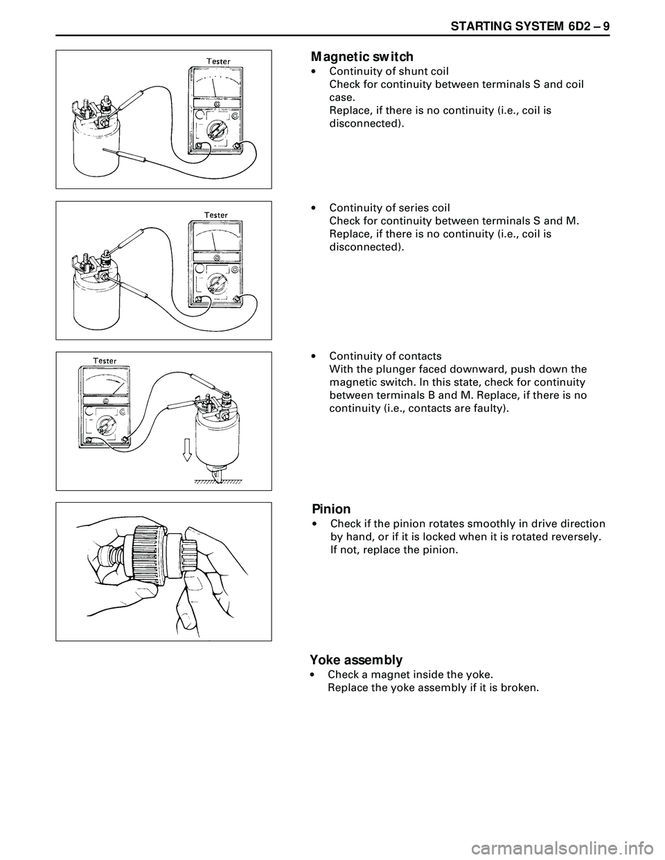
·Continuity of shunt coil
Check for continuity between terminals S and coil
case.
Replace, if there is no continuity (i.e., coil is
disconnected).
·Continuity of series coil
Check for continuity between terminals S and M.
Replace, if there is no continuity (i.e., coil is
disconnected).
Pinion
·Check if the pinion rotates smoothly in drive direction
by hand, or if it is locked when it is rotated reversely.
If not, replace the pinion.
Yoke assembly
·Check a magnet inside the yoke.
Replace the yoke assembly if it is broken. ·Continuity of contacts
With the plunger faced downward, push down the
magnetic switch. In this state, check for continuity
between terminals B and M. Replace, if there is no
continuity (i.e., contacts are faulty).
Page 1704 of 3573
6D2 Ð 10 STARTING SYSTEM
REASSEMBLY
To install, follow the removal steps in the reverse order,
noting the following points:
Grease application places
·Gears in reduction gear
·Shift lever operating portion
·Sliding portion of pinion
·Plunger sliding portion of magnetic switch
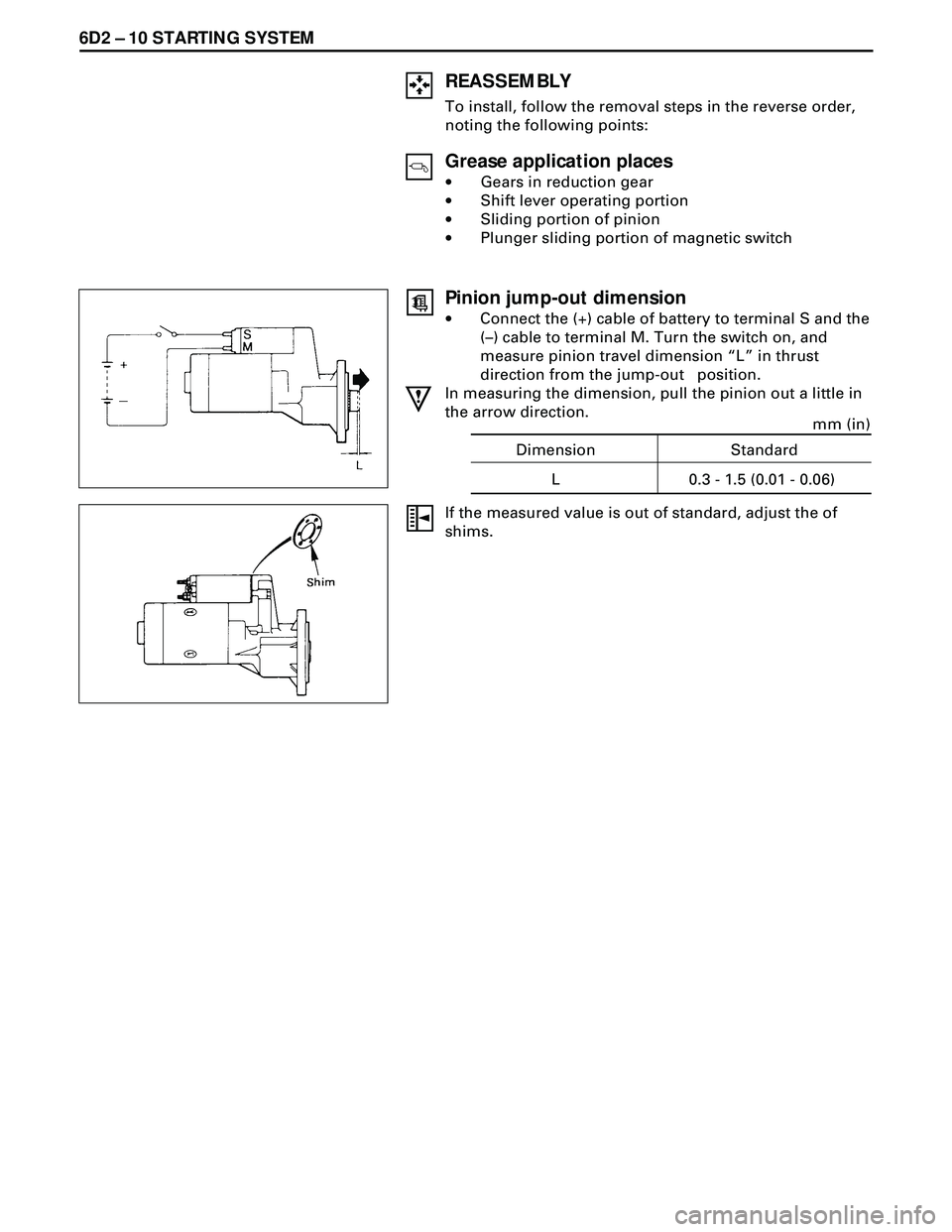
Pinion jump-out dimension
·Connect the (+) cable of battery to terminal S and the
(Ð) cable to terminal M. Turn the switch on, and
measure pinion travel dimension ÒLÓ in thrust
direction from the jump-out position.
In measuring the dimension, pull the pinion out a little in
the arrow direction.
If the measured value is out of standard, adjust the of
shims.
Dimension
L 0.3 - 1.5 (0.01 - 0.06)Standard
mm (in)
Page 1705 of 3573
STARTING SYSTEM 6D2 Ð 11
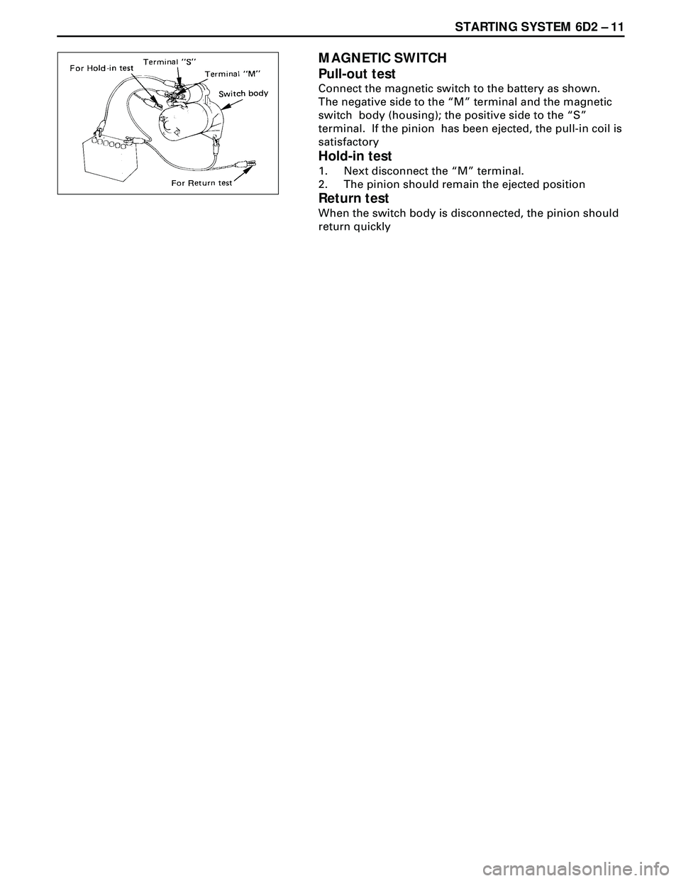
MAGNETIC SWITCH
Pull-out test
Connect the magnetic switch to the battery as shown.
The negative side to the ÒMÓ terminal and the magnetic
switch body (housing); the positive side to the ÒSÓ
terminal. If the pinion has been ejected, the pull-in coil is
satisfactory
Hold-in test
1. Next disconnect the ÒMÓ terminal.
2. The pinion should remain the ejected position
Return test
When the switch body is disconnected, the pinion should
return quickly
Page 1706 of 3573
6D2 Ð 12 STARTING SYSTEM
MEMO
Page 1707 of 3573
CHARGING SYSTEM 6D3 Ð 1
SECTION 6D3
CHARGING SYSTEM
CONTENTS
PAGE
General Description ........................................................................................................ 6D3-1
Diagnosis ......................................................................................................................... 6D3-4
Unit Repair ....................................................................................................................... 6D3-5
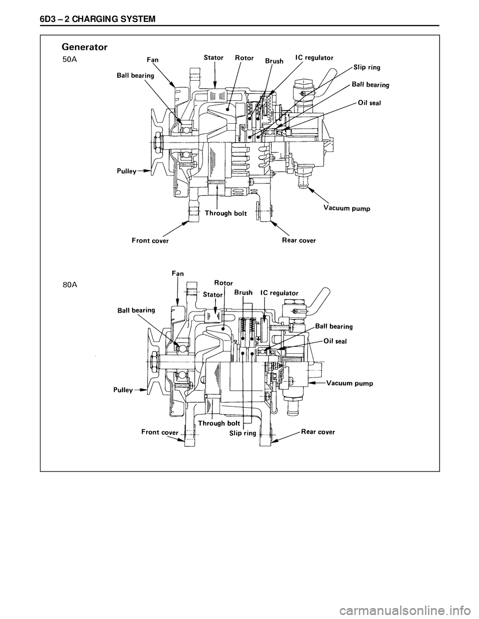
GENERAL DESCRIPTION
The generator does not require particular
maintenance such as voltage adjustment. The
rectifier connected to the stator coil has nine diodes
to transform A.C. voltage into D.C. voltage. This
D.C. voltage is connected to the output terminal of
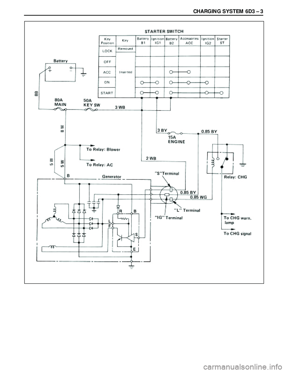
generator. The charging system is the IC integral regulator
charging system and its main components are
connected as shown in Figure.
The regulator is a solid state type and it is mounted
along with the brush holder assembly inside the
generator installed on the rear end cover.
Page 1708 of 3573
Page 1709 of 3573
Page 1710 of 3573
6D3 Ð 4 CHARGING SYSTEM
DIAGNOSIS
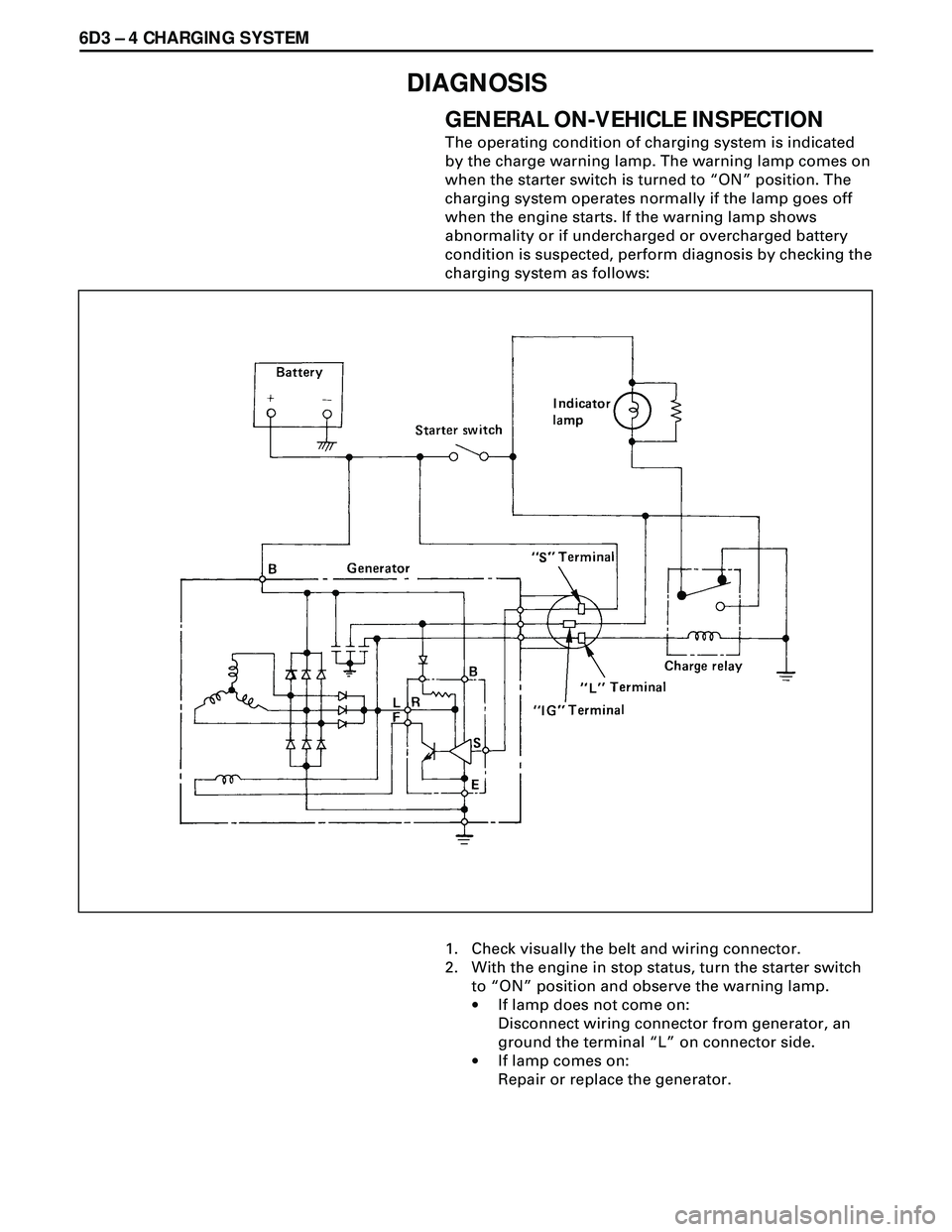
GENERAL ON-VEHICLE INSPECTION
The operating condition of charging system is indicated
by the charge warning lamp. The warning lamp comes on
when the starter switch is turned to ÒONÓ position. The
charging system operates normally if the lamp goes off
when the engine starts. If the warning lamp shows
abnormality or if undercharged or overcharged battery
condition is suspected, perform diagnosis by checking the
charging system as follows:
1. Check visually the belt and wiring connector.
2. With the engine in stop status, turn the starter switch
to ÒONÓ position and observe the warning lamp.
·If lamp does not come on:
Disconnect wiring connector from generator, an
ground the terminal ÒLÓ on connector side.
·If lamp comes on:
Repair or replace the generator.
Trending: oil change, Coolant system diagram, fuel additives, automatic transmission, instrument cluster, removing engine, fuel reserve
