ISUZU TROOPER 1998 Service Repair Manual
Manufacturer: ISUZU, Model Year: 1998, Model line: TROOPER, Model: ISUZU TROOPER 1998Pages: 3573, PDF Size: 60.36 MB
Page 1661 of 3573
ENGINE COOLING 6B Ð 7
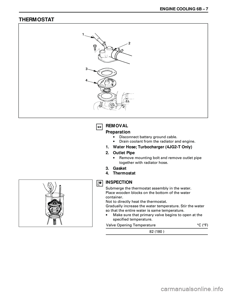
THERMOSTAT
REMOVAL
Preparation
·Disconnect battery ground cable.
·Drain coolant from the radiator and engine.
1. Water Hose; Turbocharger (4JG2-T Only)
2. Outlet Pipe
·Remove mounting bolt and remove outlet pipe
together with radiator hose.
3. Gasket
4. Thermostat
INSPECTION
Submerge the thermostat assembly in the water.
Place wooden blocks on the bottom of the water
container.
Not to directly heat the thermostat.
Gradually increase the water temperature. Stir the water
so that the entire water is same temperature.
·Make sure that primary valve begins to open at the
specified temperature.
82 (180 )
°C (°F) Valve Opening Temperature
Page 1662 of 3573
6B Ð 8 ENGINE COOLING
·Make sure that secondary valve opens fully at the
specified temperature.
Make necessary repair and parts replacement if extreme
wear or damage is found during inspection.
INSTALLATION
4. Thermostat
3. Gasket
2. Outlet Pipe
·Connect outlet pipe and tighten bolts to the
specified torque.
19(1.9/14)
N·m (Kgm/lb·ft)
1. Water Hose: Turbocharger (4JG2-T Only)
·Install battery ground cable.
·Pour coolant,
·Start the engine and check coolant leakage.
95 (203)
°C (°F) Valve Full Open Temperature
Page 1663 of 3573
ENGINE COOLING 6B Ð 9
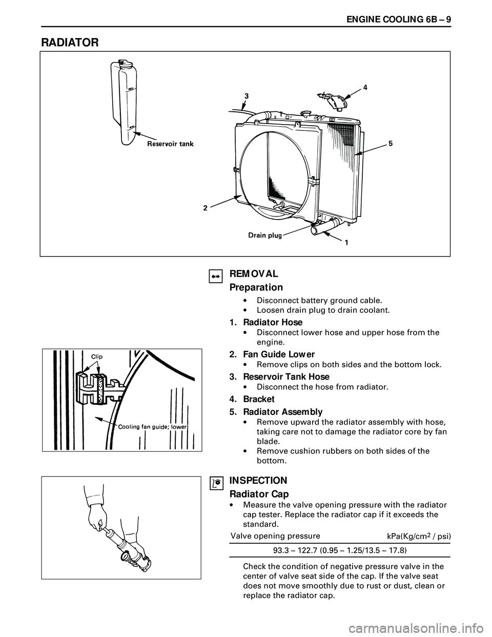
RADIATOR
REMOVAL
Preparation
·Disconnect battery ground cable.
·Loosen drain plug to drain coolant.
1. Radiator Hose
·Disconnect lower hose and upper hose from the
engine.
2. Fan Guide Lower
·Remove clips on both sides and the bottom lock.
3. Reservoir Tank Hose
·Disconnect the hose from radiator.
4. Bracket
5. Radiator Assembly
·Remove upward the radiator assembly with hose,
taking care not to damage the radiator core by fan
blade.
·Remove cushion rubbers on both sides of the
bottom.
INSPECTION
Radiator Cap
·Measure the valve opening pressure with the radiator
cap tester. Replace the radiator cap if it exceeds the
standard.
Check the condition of negative pressure valve in the
center of valve seat side of the cap. If the valve seat
does not move smoothly due to rust or dust, clean or
replace the radiator cap.
Valve opening pressure
93.3 – 122.7 (0.95 – 1.25/13.5 – 17.8)kPa(Kg/cm2 / psi)
Page 1664 of 3573
6B Ð 10 ENGINE COOLING
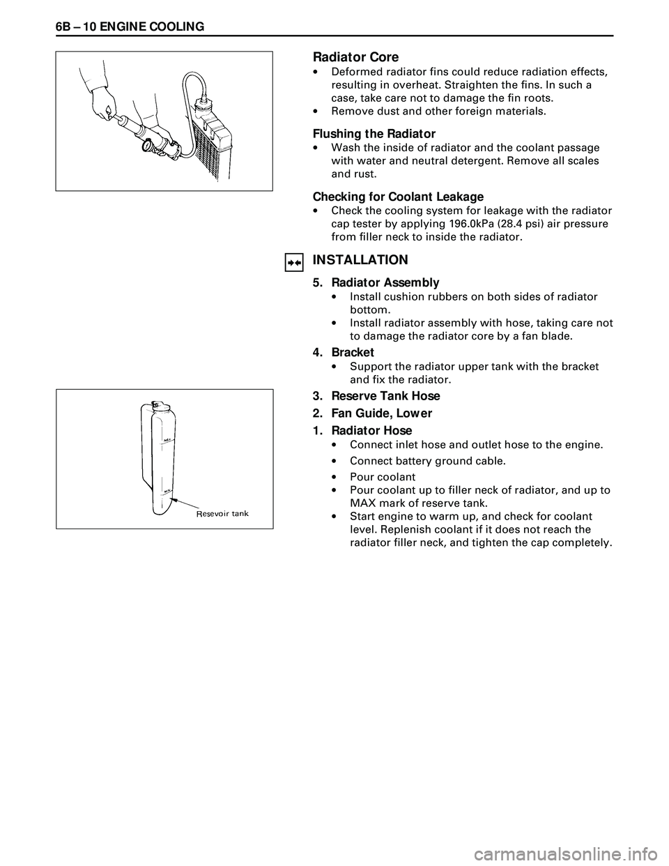
Radiator Core
·Deformed radiator fins could reduce radiation effects,
resulting in overheat. Straighten the fins. In such a
case, take care not to damage the fin roots.
·Remove dust and other foreign materials.
Flushing the Radiator
·Wash the inside of radiator and the coolant passage
with water and neutral detergent. Remove all scales
and rust.
Checking for Coolant Leakage
·Check the cooling system for leakage with the radiator
cap tester by applying 196.0kPa (28.4 psi) air pressure
from filler neck to inside the radiator.
INSTALLATION
5. Radiator Assembly
·Install cushion rubbers on both sides of radiator
bottom.
·Install radiator assembly with hose, taking care not
to damage the radiator core by a fan blade.
4. Bracket
·Support the radiator upper tank with the bracket
and fix the radiator.
3. Reserve Tank Hose
2. Fan Guide, Lower
1. Radiator Hose
·Connect inlet hose and outlet hose to the engine.
·Connect battery ground cable.
·Pour coolant
·Pour coolant up to filler neck of radiator, and up to
MAX mark of reserve tank.
·Start engine to warm up, and check for coolant
level. Replenish coolant if it does not reach the
radiator filler neck, and tighten the cap completely.
Page 1665 of 3573
ENGINE COOLING 6B Ð 11
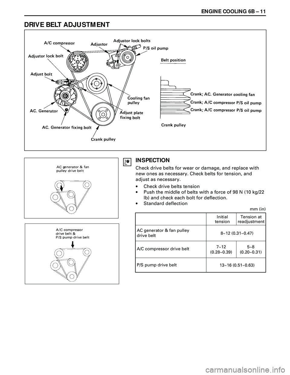
DRIVE BELT ADJUSTMENT
INSPECTION
Check drive belts for wear or damage, and replace with
new ones as necessary. Check belts for tension, and
adjust as necessary.
·Check drive belts tension
·Push the middle of belts with a force of 98 N (10 kg/22
lb) and check each bolt for deflection.
·Standard deflection
AC generator & fan pulley
drive beltInitial
tensionTension at
readjustment8~12 (0.31~0.47)
A/C compressor drive belt7~12
(0.28~0.39)5~8
(0.20~0.31)
mm (in)
P/S pump drive belt
13~16 (0.51~0.63)
Page 1666 of 3573
6B Ð 12 ENGINE COOLING
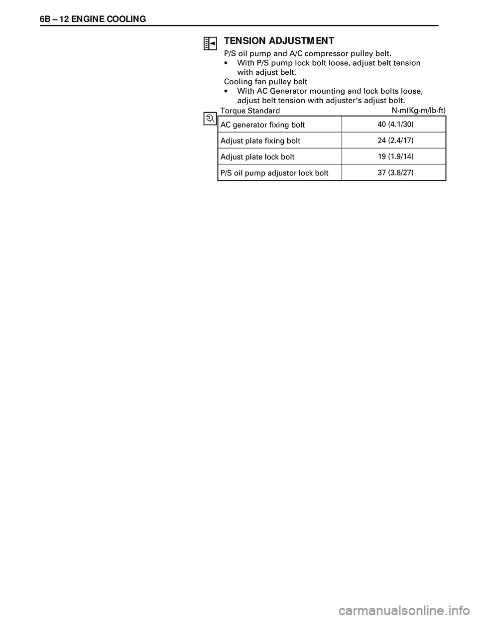
TENSION ADJUSTMENT
P/S oil pump and A/C compressor pulley belt.
·With P/S pump lock bolt loose, adjust belt tension
with adjust belt.
Cooling fan pulley belt
·With AC Generator mounting and lock bolts loose,
adjust belt tension with adjuster's adjust bolt.
AC generator fixing bolt40 (4.1/30) Torque StandardN·m(Kg·m/lb·ft)
Adjust plate fixing bolt24 (2.4/17)
Adjust plate lock bolt19 (1.9/14)
P/S oil pump adjustor lock bolt37 (3.8/27)
Page 1667 of 3573
FUEL SYSTEM 6C Ð 1
PAGE
General Description ....................................................................................................................... 6C- 1
On-Vehicle Service ......................................................................................................................... 6C- 7
Fuel Filter Assembly .................................................................................................................. 6C- 7
Fuel Filter Cartrige ..................................................................................................................... 6C- 8
Injection nozzle .......................................................................................................................... 6C- 9
Injection Pump Assembly ......................................................................................................... 6C-14
Fuel Tank .................................................................................................................................... 6C-18
Fuel Gauge Unit ......................................................................................................................... 6C-19
Fuel Filler Cap ............................................................................................................................ 6C-20
Accelerator Control ........................................................................................................................ 6C-21
Accelerator Control Cable ........................................................................................................ 6C-21
Accelerator Pedal ...................................................................................................................... 6C-23
Air Cleaner .................................................................................................................................. 6C-24
SECTION 6C
FUEL SYSTEM
CONTENTS
GENERAL DESCRIPTION
When working on the fuel system, there are several
things to keep in mind:
·Any time the fuel system is being worked on,
disconnect the negative battery cable except for
those tests where battery voltage is required.
·Always keep a dry chemical (Class B) fire extin-
guisher near the work area.
·Replace all pipes with the same pipe and fittings
that were removed.
Clean and inspect ÒOÓ rings. Replace where
required.
·Always relieve the line pressure before servicing
any fuel system components.·Do not attempt repairs on the fuel system until
you have read the instructions and checked the
pictures relating to that repair.
Page 1668 of 3573
6C Ð 2 FUEL SYSTEM
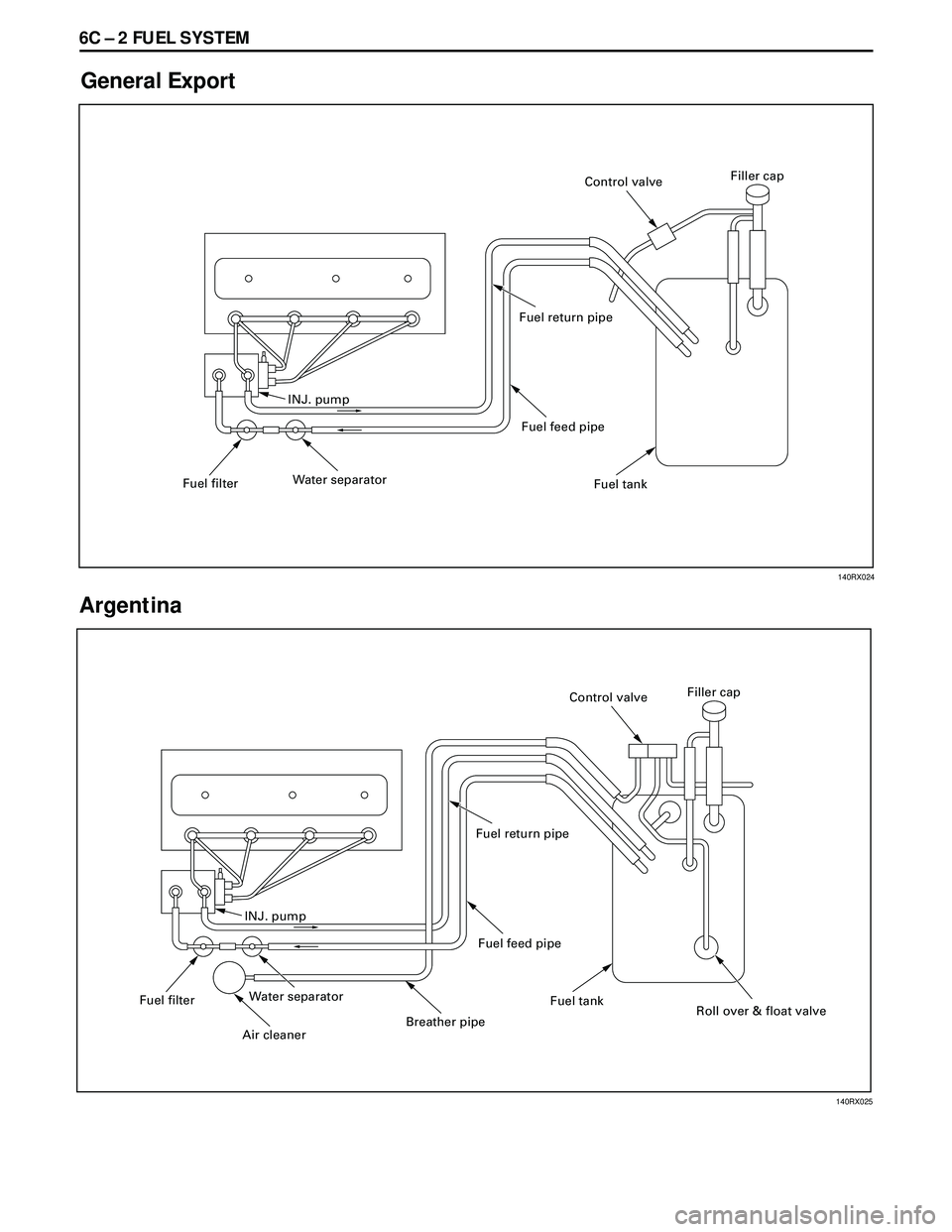
General Export
Argentina
INJ. pump
Fuel filterWater separatorFuel feed pipe Fuel return pipe
Fuel tankFiller cap
Control valve
INJ. pump
Fuel filterWater separator
Air cleaner
Breather pipeFuel feed pipe Fuel return pipe
Fuel tank
Roll over & float valve Filler cap
Control valve
140RX024
140RX025
Page 1669 of 3573
FUEL SYSTEM 6C Ð 3
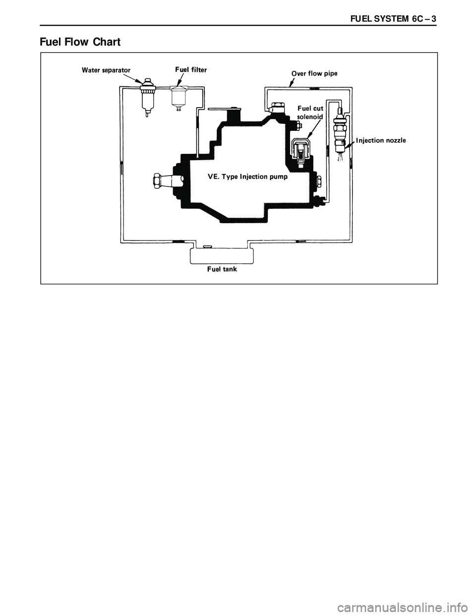
Fuel Flow Chart
Page 1670 of 3573
6C Ð 4 FUEL SYSTEM
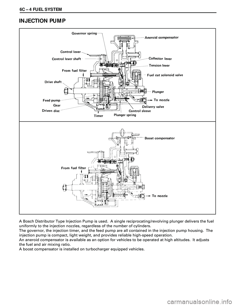
INJECTION PUMP
A Bosch Distributor Type Injection Pump is used. A single reciprocating/revolving plunger delivers the fuel
uniformly to the injection nozzles, regardless of the number of cylinders.
The governor, the injection timer, and the feed pump are all contained in the injection pump housing. The
injection pump is compact, light weight, and provides reliable high-speed operation.
An aneroid compensator is available as an option for vehicles to be operated at high altitudes. It adjusts
the fuel and air mixing ratio.
A boost compensator is installed on turbocharger equipped vehicles.