ISUZU TROOPER 1998 Service Repair Manual
TROOPER 1998
ISUZU
ISUZU
https://www.carmanualsonline.info/img/61/57184/w960_57184-0.png
ISUZU TROOPER 1998 Service Repair Manual
Trending: climate control, Wiring diagram eci, transmission fluid, heater, catalytic converter, engine coolant, maintenance
Page 321 of 3573
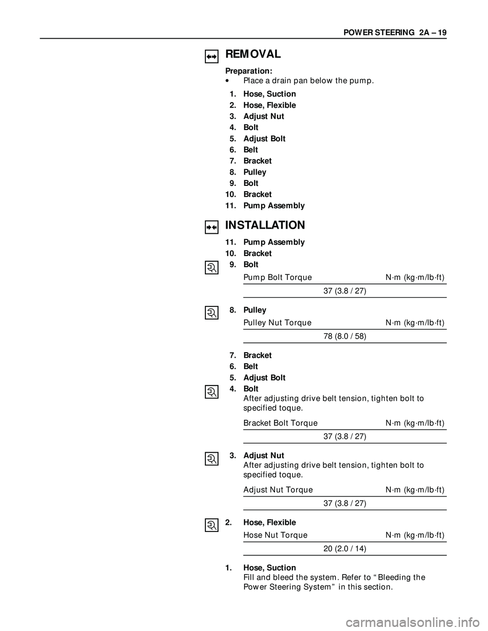
REMOVAL
Preparation:
•Place a drain pan below the pump.
1. Hose, Suction
2. Hose, Flexible
3. Adjust Nut
4. Bolt
5. Adjust Bolt
6. Belt
7. Bracket
8. Pulley
9. Bolt
10. Bracket
11. Pump Assembly
INSTALLATION
11. Pump Assembly
10. Bracket
9. Bolt
Pump Bolt Torque N·m (kg·m/lb·ft)
37 (3.8 / 27)
8. Pulley
Pulley Nut Torque N·m (kg·m/lb·ft)
78 (8.0 / 58)
7. Bracket
6. Belt
5. Adjust Bolt
4. Bolt
After adjusting drive belt tension, tighten bolt to
specified toque.
Bracket Bolt Torque N·m (kg·m/lb·ft)
37 (3.8 / 27)
3. Adjust Nut
After adjusting drive belt tension, tighten bolt to
specified toque.
Adjust Nut Torque N·m (kg·m/lb·ft)
37 (3.8 / 27)
2. Hose, Flexible
Hose Nut Torque N·m (kg·m/lb·ft)
20 (2.0 / 14)
1. Hose, Suction
Fill and bleed the system. Refer to “Bleeding the
Power Steering System” in this section.POWER STEERING 2A – 19
Page 322 of 3573
2A – 20 POWER STEERING
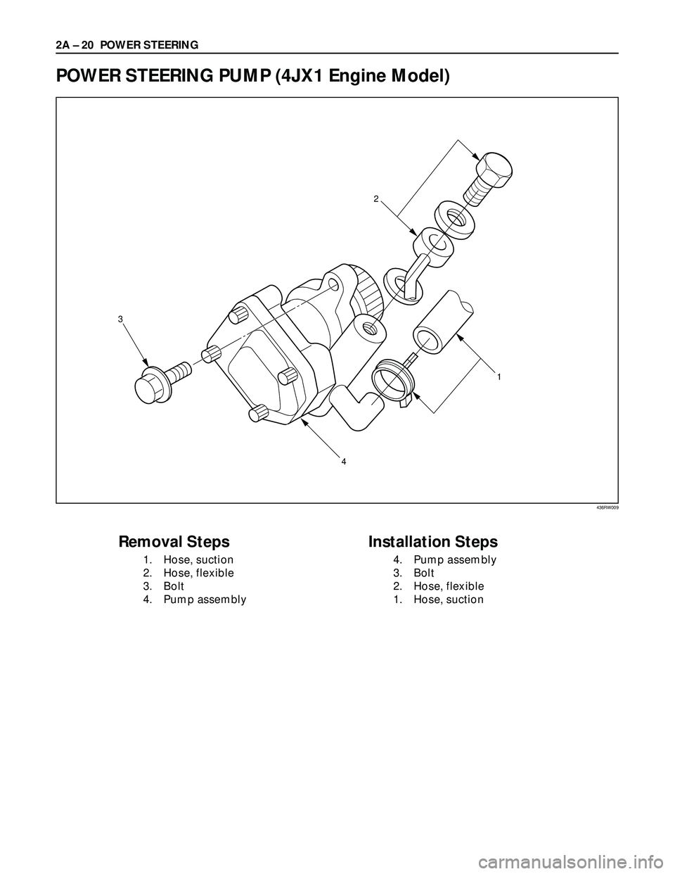
POWER STEERING PUMP (4JX1 Engine Model)
3
2
1
4
Removal Steps
1. Hose, suction
2. Hose, flexible
3. Bolt
4. Pump assembly
Installation Steps
4. Pump assembly
3. Bolt
2. Hose, flexible
1. Hose, suction
436RW009
Page 323 of 3573
POWER STEERING 2A – 21
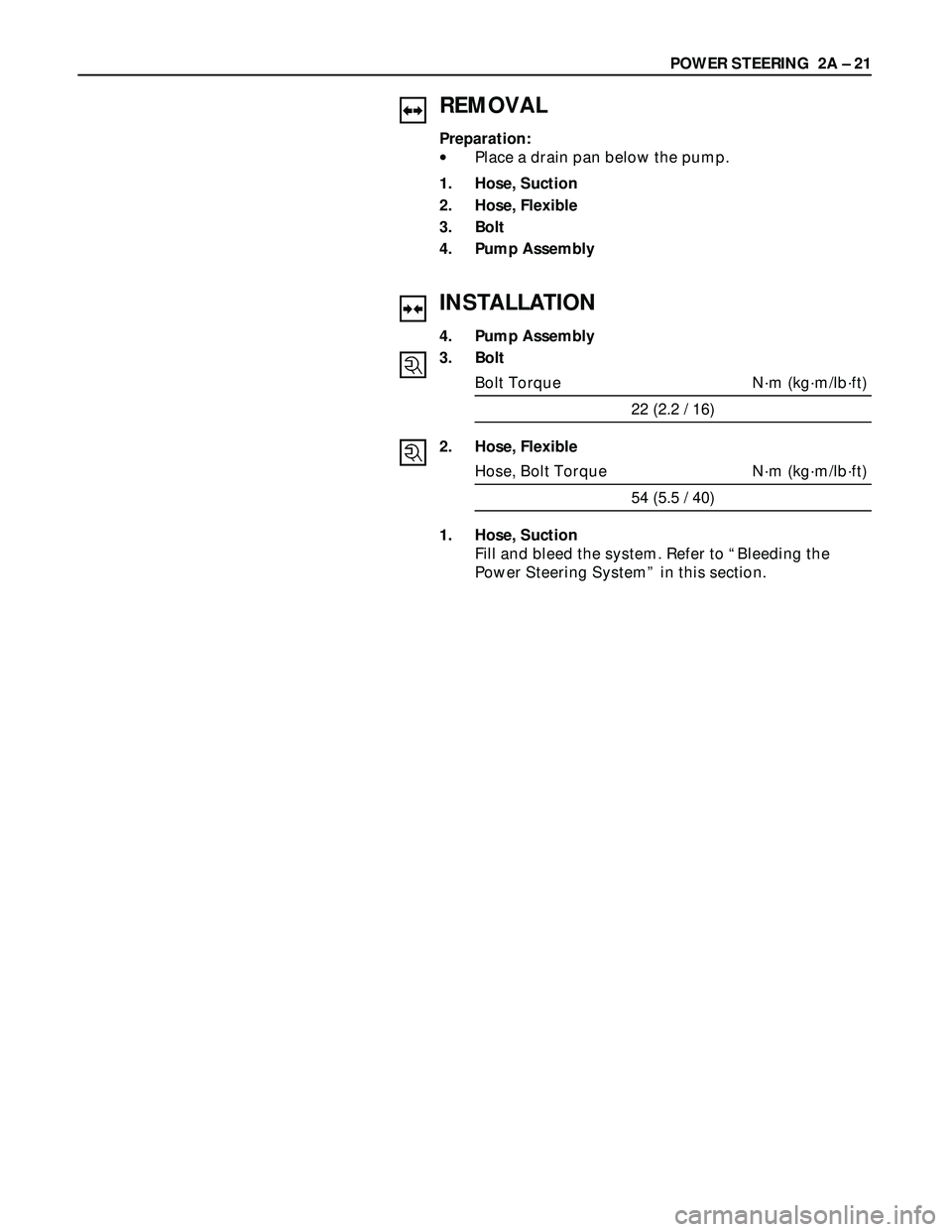
REMOVAL
Preparation:
•Place a drain pan below the pump.
1. Hose, Suction
2. Hose, Flexible
3. Bolt
4. Pump Assembly
INSTALLATION
4. Pump Assembly
3. Bolt
Bolt Torque N·m (kg·m/lb·ft)
22 (2.2 / 16)
2. Hose, Flexible
Hose, Bolt Torque N·m (kg·m/lb·ft)
54 (5.5 / 40)
1. Hose, Suction
Fill and bleed the system. Refer to “Bleeding the
Power Steering System” in this section.
Page 324 of 3573
2A – 22 POWER STEERING
UNIT REPAIR
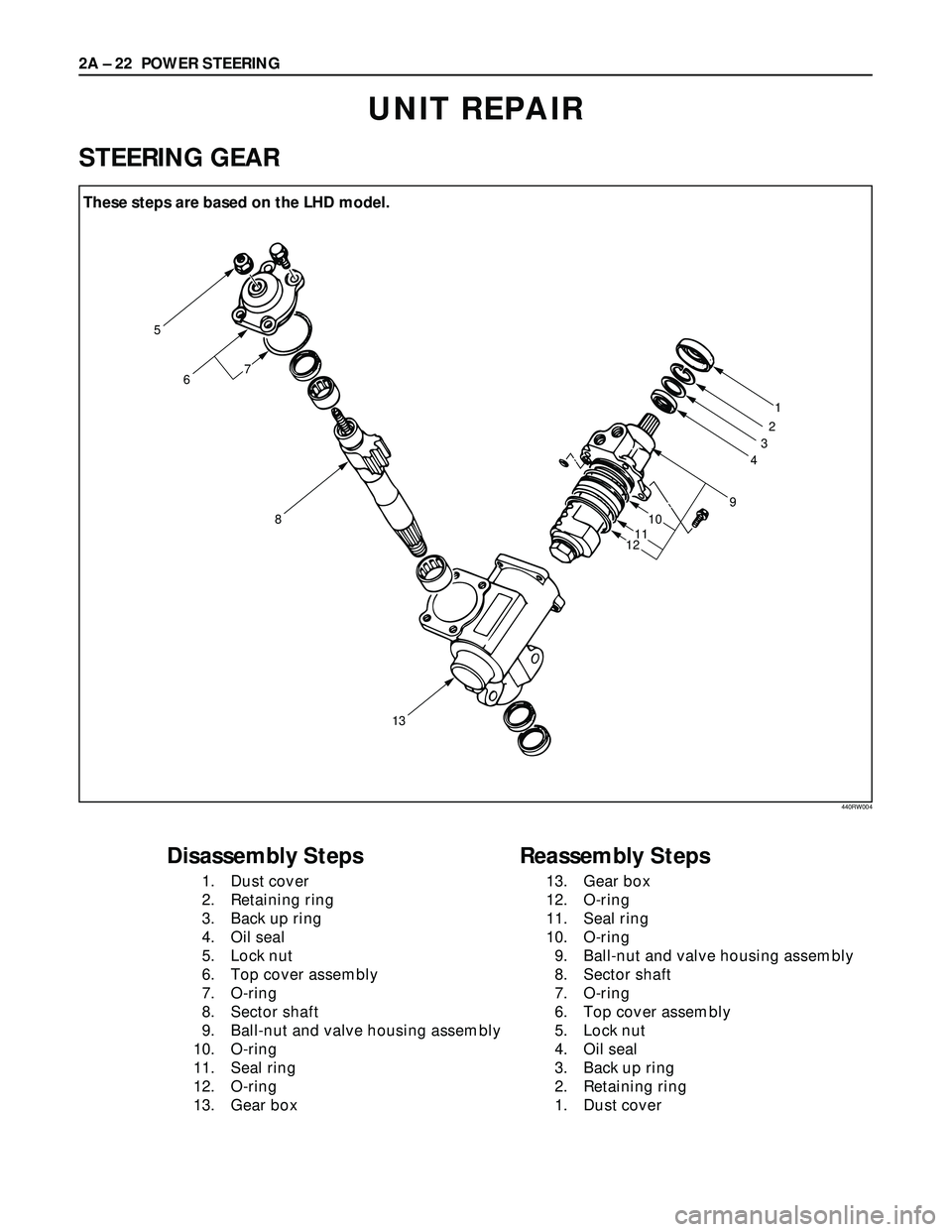
STEERING GEAR
5 These steps are based on the LHD model
6
8
131
2
3
4
9
10
11
12
7
Disassembly Steps
1. Dust cover
2. Retaining ring
3. Back up ring
4. Oil seal
5. Lock nut
6. Top cover assembly
7. O-ring
8. Sector shaft
9. Ball-nut and valve housing assembly
10. O-ring
11. Seal ring
12. O-ring
13. Gear box
Reassembly Steps
13. Gear box
12. O-ring
11. Seal ring
10. O-ring
9. Ball-nut and valve housing assembly
8. Sector shaft
7. O-ring
6. Top cover assembly
5. Lock nut
4. Oil seal
3. Back up ring
2. Retaining ring
1. Dust cover
440RW004
These steps are based on the LHD model.
Page 325 of 3573
POWER STEERING 2A – 23
DISASSEMBLY
CAUTION:
Do not clamp the steering gear assembly in a vise by the
power cylinder housing.
1. Dust Cover
2. Retaining Ring
3. Back up RIng
4. Oil Seal
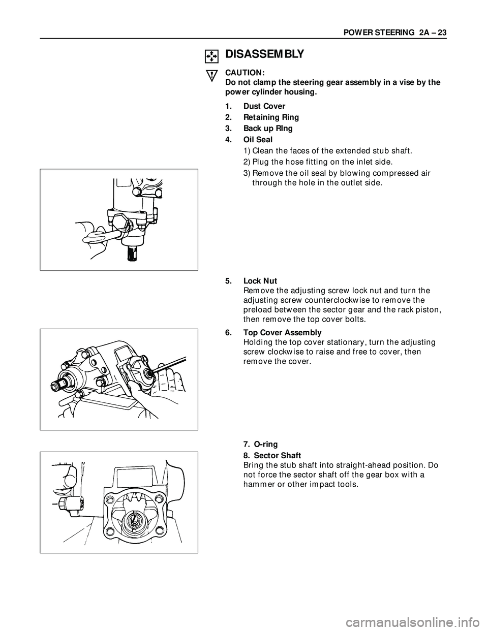
1) Clean the faces of the extended stub shaft.
2) Plug the hose fitting on the inlet side.
3) Remove the oil seal by blowing compressed air
through the hole in the outlet side.
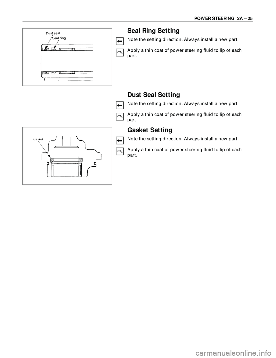
5. Lock Nut
Remove the adjusting screw lock nut and turn the
adjusting screw counterclockwise to remove the
preload between the sector gear and the rack piston,
then remove the top cover bolts.
6. Top Cover Assembly
Holding the top cover stationary, turn the adjusting
screw clockwise to raise and free to cover, then
remove the cover.
7. O-ring
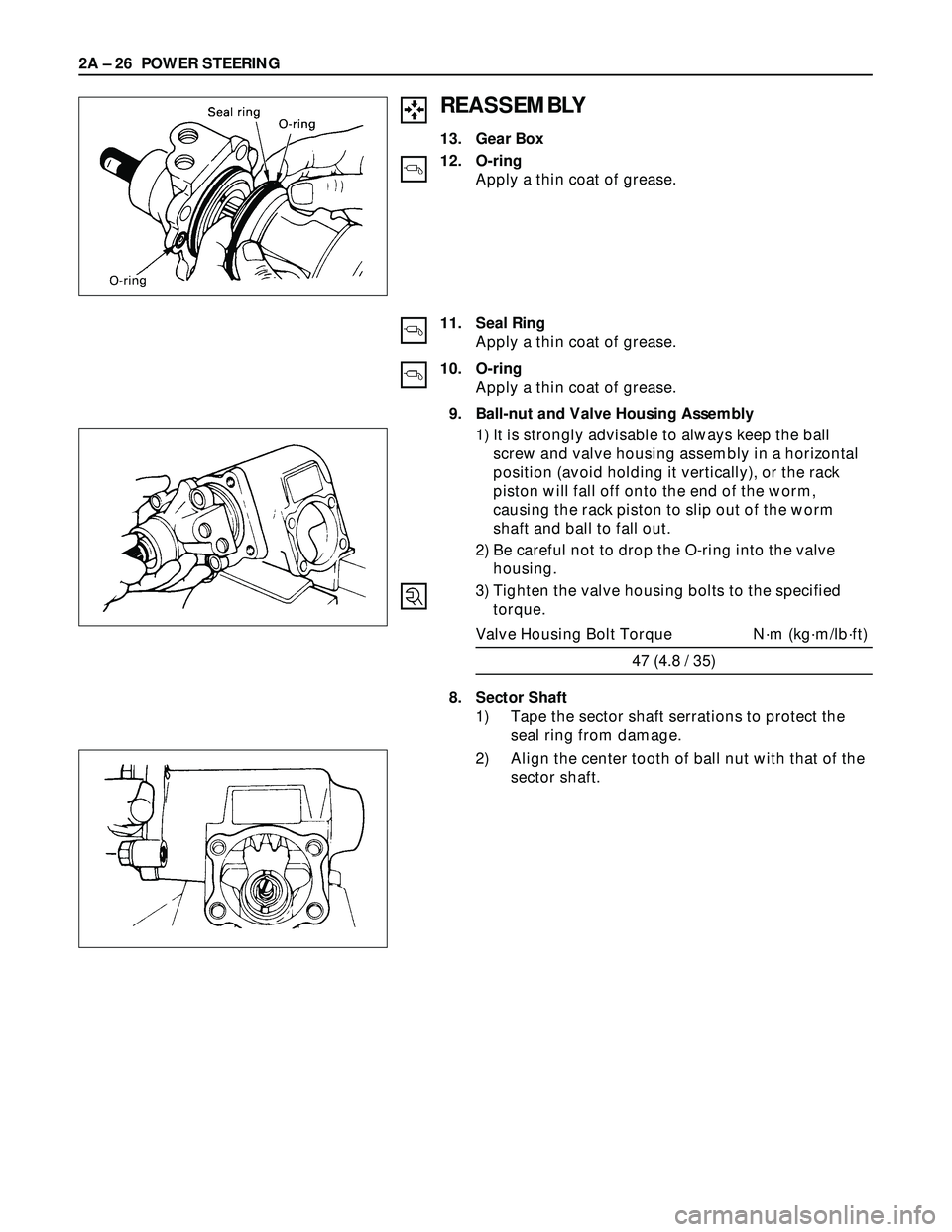
8. Sector Shaft
Bring the stub shaft into straight-ahead position. Do
not force the sector shaft off the gear box with a
hammer or other impact tools.
Page 326 of 3573
2A – 24 POWER STEERING
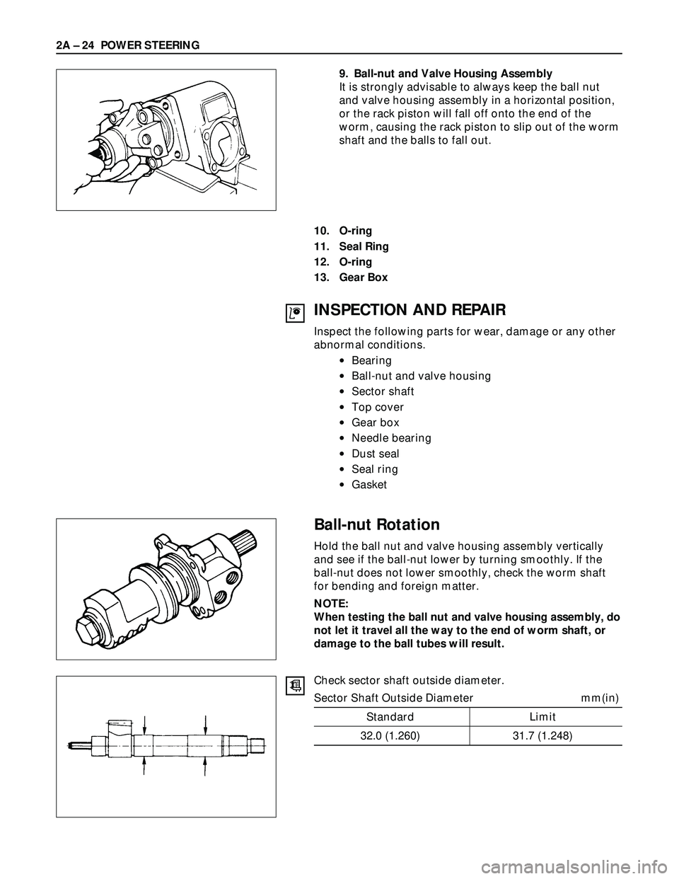
9. Ball-nut and Valve Housing Assembly
It is strongly advisable to always keep the ball nut
and valve housing assembly in a horizontal position,
or the rack piston will fall off onto the end of the
worm, causing the rack piston to slip out of the worm
shaft and the balls to fall out.
10. O-ring
11. Seal Ring
12. O-ring
13. Gear Box
INSPECTION AND REPAIR
Inspect the following parts for wear, damage or any other
abnormal conditions.
•Bearing
•Ball-nut and valve housing
•Sector shaft
•Top cover
•Gear box
•Needle bearing
•Dust seal
•Seal ring
•Gasket
Ball-nut Rotation
Hold the ball nut and valve housing assembly vertically
and see if the ball-nut lower by turning smoothly. If the
ball-nut does not lower smoothly, check the worm shaft
for bending and foreign matter.
NOTE:
When testing the ball nut and valve housing assembly, do
not let it travel all the way to the end of worm shaft, or
damage to the ball tubes will result.
Check sector shaft outside diameter.
Sector Shaft Outside Diameter mm(in)
Standard Limit
32.0 (1.260) 31.7 (1.248)
Page 327 of 3573
POWER STEERING 2A – 25
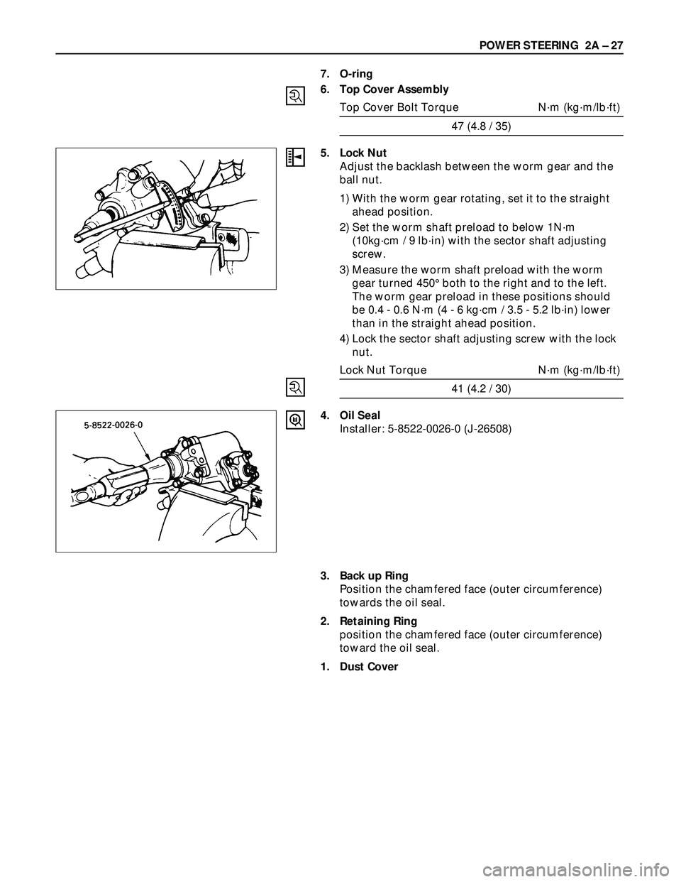
Seal Ring Setting
Note the setting direction. Always install a new part.
Apply a thin coat of power steering fluid to lip of each
part.
Dust Seal Setting
Note the setting direction. Always install a new part.
Apply a thin coat of power steering fluid to lip of each
part.
Gasket Setting
Note the setting direction. Always install a new part.
Apply a thin coat of power steering fluid to lip of each
part.
Page 328 of 3573
2A – 26 POWER STEERING
REASSEMBLY
13. Gear Box
12. O-ring
Apply a thin coat of grease.
11. Seal Ring
Apply a thin coat of grease.
10. O-ring
Apply a thin coat of grease.
9. Ball-nut and Valve Housing Assembly
1) It is strongly advisable to always keep the ball
screw and valve housing assembly in a horizontal
position (avoid holding it vertically), or the rack
piston will fall off onto the end of the worm,
causing the rack piston to slip out of the worm
shaft and ball to fall out.
2) Be careful not to drop the O-ring into the valve
housing.
3) Tighten the valve housing bolts to the specified
torque.
Valve Housing Bolt Torque N·m (kg·m/lb·ft)
47 (4.8 / 35)
8. Sector Shaft
1) Tape the sector shaft serrations to protect the
seal ring from damage.
2) Align the center tooth of ball nut with that of the
sector shaft.
Page 329 of 3573
POWER STEERING 2A – 27
7. O-ring
6. Top Cover Assembly
Top Cover Bolt Torque N·m (kg·m/lb·ft)
47 (4.8 / 35)
5. Lock Nut
Adjust the backlash between the worm gear and the
ball nut.
1) With the worm gear rotating, set it to the straight
ahead position.
2) Set the worm shaft preload to below 1N·m
(10kg·cm / 9 lb·in) with the sector shaft adjusting
screw.
3) Measure the worm shaft preload with the worm
gear turned 450°both to the right and to the left.
The worm gear preload in these positions should
be 0.4 - 0.6 N·m (4 - 6 kg·cm / 3.5 - 5.2 lb·in) lower
than in the straight ahead position.
4) Lock the sector shaft adjusting screw with the lock
nut.
Lock Nut Torque N·m (kg·m/lb·ft)
41 (4.2 / 30)
4. Oil Seal
Installer: 5-8522-0026-0 (J-26508)
3. Back up Ring
Position the chamfered face (outer circumference)
towards the oil seal.
2. Retaining Ring
position the chamfered face (outer circumference)
toward the oil seal.
1. Dust Cover
Page 330 of 3573
2A – 28 POWER STEERING
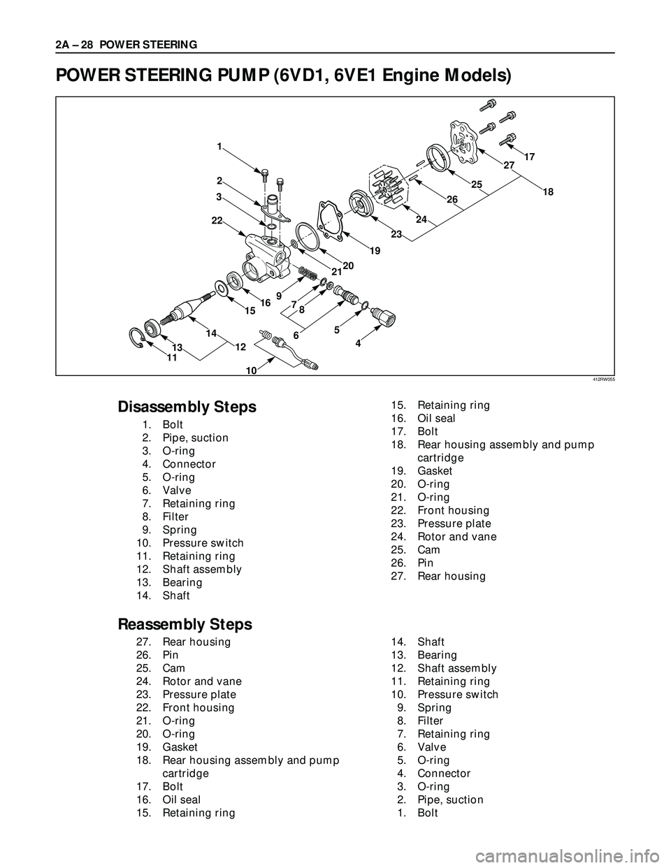
POWER STEERING PUMP (6VD1, 6VE1 Engine Models)
2
3
221
1615
12
11
56
879
4
17
1827
25
26
24
19
20
23
21
14
13
10
Disassembly Steps
1. Bolt
2. Pipe, suction
3. O-ring
4. Connector
5. O-ring
6. Valve
7. Retaining ring
8. Filter
9. Spring
10. Pressure switch
11. Retaining ring
12. Shaft assembly
13. Bearing
14. Shaft15. Retaining ring
16. Oil seal
17. Bolt
18. Rear housing assembly and pump
cartridge
19. Gasket
20. O-ring
21. O-ring
22. Front housing
23. Pressure plate
24. Rotor and vane
25. Cam
26. Pin
27. Rear housing
Reassembly Steps
27. Rear housing
26. Pin
25. Cam
24. Rotor and vane
23. Pressure plate
22. Front housing
21. O-ring
20. O-ring
19. Gasket
18. Rear housing assembly and pump
cartridge
17. Bolt
16. Oil seal
15. Retaining ring14. Shaft
13. Bearing
12. Shaft assembly
11. Retaining ring
10. Pressure switch
9. Spring
8. Filter
7. Retaining ring
6. Valve
5. O-ring
4. Connector
3. O-ring
2. Pipe, suction
1. Bolt
412RW055
Trending: rear view mirror, removing engine, headlights, four wheel drive, jacking, display, radiator
