odometer JAGUAR S TYPE 2005 1.G Technical Guide Update
[x] Cancel search | Manufacturer: JAGUAR, Model Year: 2005, Model line: S TYPE, Model: JAGUAR S TYPE 2005 1.GPages: 133, PDF Size: 3.48 MB
Page 81 of 133
JAGUARS-TYPEElectrical/Electronic
76Air Conditioning Control Module (A/CCM)
The A/CCM is connected to the SCP
communication network. The A/CCM controls
automatic climate functions that maintain the
vehicle at a constant temperature setting.
Instrument Pack
The instrument pack is connected to the SCP
communication network. The instrument pack
displays information received on the SCP
including speedometer, odometer, fuel, and
message center warnings. The instrument pack
also controls the passive anti-theft system (PATS).
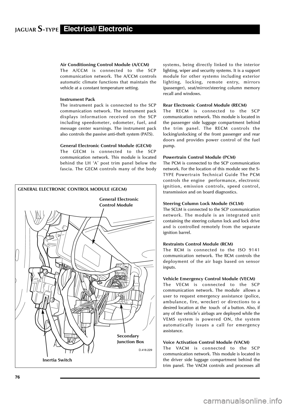
General Electronic Control Module (GECM)
The GECM is connected to the SCP
communication network. This module is located
behind the LH ÔAÕ post trim panel below the
fascia. The GECM controls many of the bodysystems, being directly linked to the interior
lighting, wiper and security systems. It is a support
module for other systems including exterior
lighting, locking, remote entry, mirrors
(passenger), seat/mirror/steering column memory
recall and windows.
Rear Electronic Control Module (RECM)
The RECM is connected to the SCP
communication network. This module is located in
the passenger side luggage compartment behind
the trim panel. The RECM controls the
locking/unlocking of the front passenger and rear
doors and provides power control of the fuel
pump.
Powertrain Control Module (PCM)
The PCM is connected to the SCP communication
network. For the location of this module see the S-
TYPE Powertrain Technical Guide The PCM
controls the engine performance, electronic
ignition, emission controls, speed control,
transmission and on board diagnostics.
Steering Column Lock Module (SCLM)
The SCLM is connected to the SCP communication
network. The module is an integrated unit
containing the steering column lock and lock drive
and is controlled remotely from the separate
ignition barrel.
Restraints Control Module (RCM)
The RCM is connected to the ISO 9141
communication network. The RCM controls the
deployment of the air bags based on sensor
inputs.
Vehicle Emergency Control Module (VECM)
The VECM is connected to the SCP
communication network. The module allows a
user to request emergency assistance (police,
ambulance, fire, wrecker) or directions to a
desired location at the touch of a button. Also, if
any of the vehicleÕs airbags are deployed while the
VEMS system is powered ON, the system
automatically issues a call for emergency
assistance.
Voice Activation Control Module (VACM)
The VACM is connected to the SCP
communication network. This module is located in
the driver side luggage compartment behind the
trim panel. The VACM controls and processes all
D.418.229
GENERAL ELECTRONIC CONTROL MODULE (GECM)
Inertia Switch
Secondary
Junction Box
General Electronic
Control Module
Page 100 of 133
JAGUARS-TYPEElectrical/Electronic
95
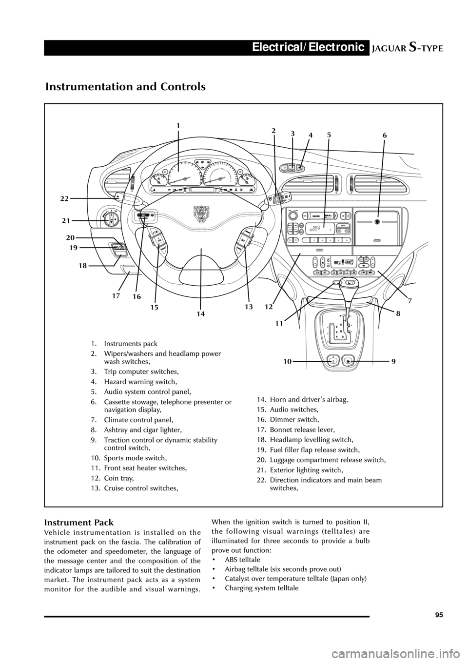
Instrumentation and Controls
1. Instruments pack
2. Wipers/washers and headlamp power
wash switches,
3. Trip computer switches,
4. Hazard warning switch,
5. Audio system control panel,
6. Cassette stowage, telephone presenter or
navigation display,
7. Climate control panel,
8. Ashtray and cigar lighter,
9. Traction control or dynamic stability
control switch,
10. Sports mode switch,
11. Front seat heater switches,
12. Coin tray,
13. Cruise control switches,
14. Horn and driverÕs airbag,
15. Audio switches,
16. Dimmer switch,
17. Bonnet release lever,
18. Headlamp levelling switch,
19. Fuel filler flap release switch,
20. Luggage compartment release switch,
21. Exterior lighting switch,
22. Direction indicators and main beam
switches,
1
7
8
9 10 11 12 13 19
16 17 18 20 21 22
142
3
45
6
15
Instrument Pack
Vehicle instrumentation is installed on the
instrument pack on the fascia. The calibration of
the odometer and speedometer, the language of
the message center and the composition of the
indicator lamps are tailored to suit the destination
market. The instrument pack acts as a system
monitor for the audible and visual warnings.When the ignition switch is turned to position II,
the following visual warnings (telltales) are
illuminated for three seconds to provide a bulb
prove out function:
¥ ABS telltale
¥ Airbag telltale (six seconds prove out)
¥ Catalyst over temperature telltale (Japan only)
¥ Charging system telltale
Page 101 of 133
JAGUARS-TYPEElectrical/Electronic
96
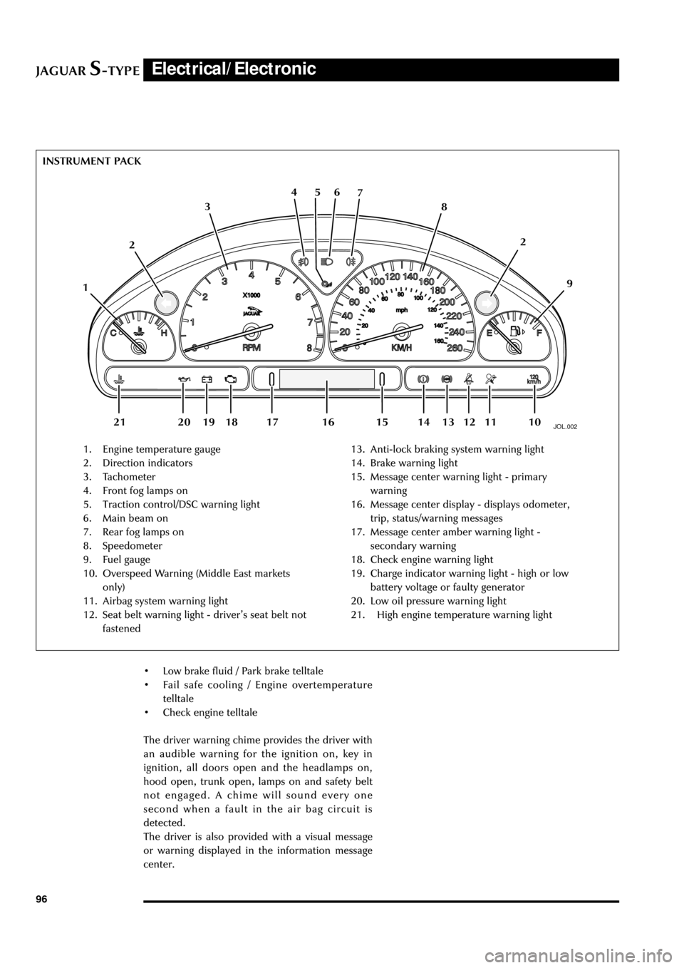
JOL.002
1. Engine temperature gauge
2. Direction indicators
3. Tachometer
4. Front fog lamps on
5. Traction control/DSC warning light
6. Main beam on
7. Rear fog lamps on
8. Speedometer
9. Fuel gauge
10. Overspeed Warning (Middle East markets
only)
11. Airbag system warning light
12. Seat belt warning light - driverÕs seat belt not
fastened13. Anti-lock braking system warning light
14. Brake warning light
15. Message center warning light - primary
warning
16. Message center display - displays odometer,
trip, status/warning messages
17. Message center amber warning light -
secondary warning
18. Check engine warning light
19. Charge indicator warning light - high or low
battery voltage or faulty generator
20. Low oil pressure warning light
21. High engine temperature warning light INSTRUMENT PACK
126 5 4
3
109 8 7
112
13 12 18 20 19 1416 15 17 21
¥ Low brake fluid / Park brake telltale
¥ Fail safe cooling / Engine overtemperature
telltale
¥ Check engine telltale
The driver warning chime provides the driver with
an audible warning for the ignition on, key in
ignition, all doors open and the headlamps on,
hood open, trunk open, lamps on and safety belt
not engaged. A chime will sound every one
second when a fault in the air bag circuit is
detected.
The driver is also provided with a visual message
or warning displayed in the information message
center.
Page 102 of 133
JAGUARS-TYPEElectrical/Electronic
97
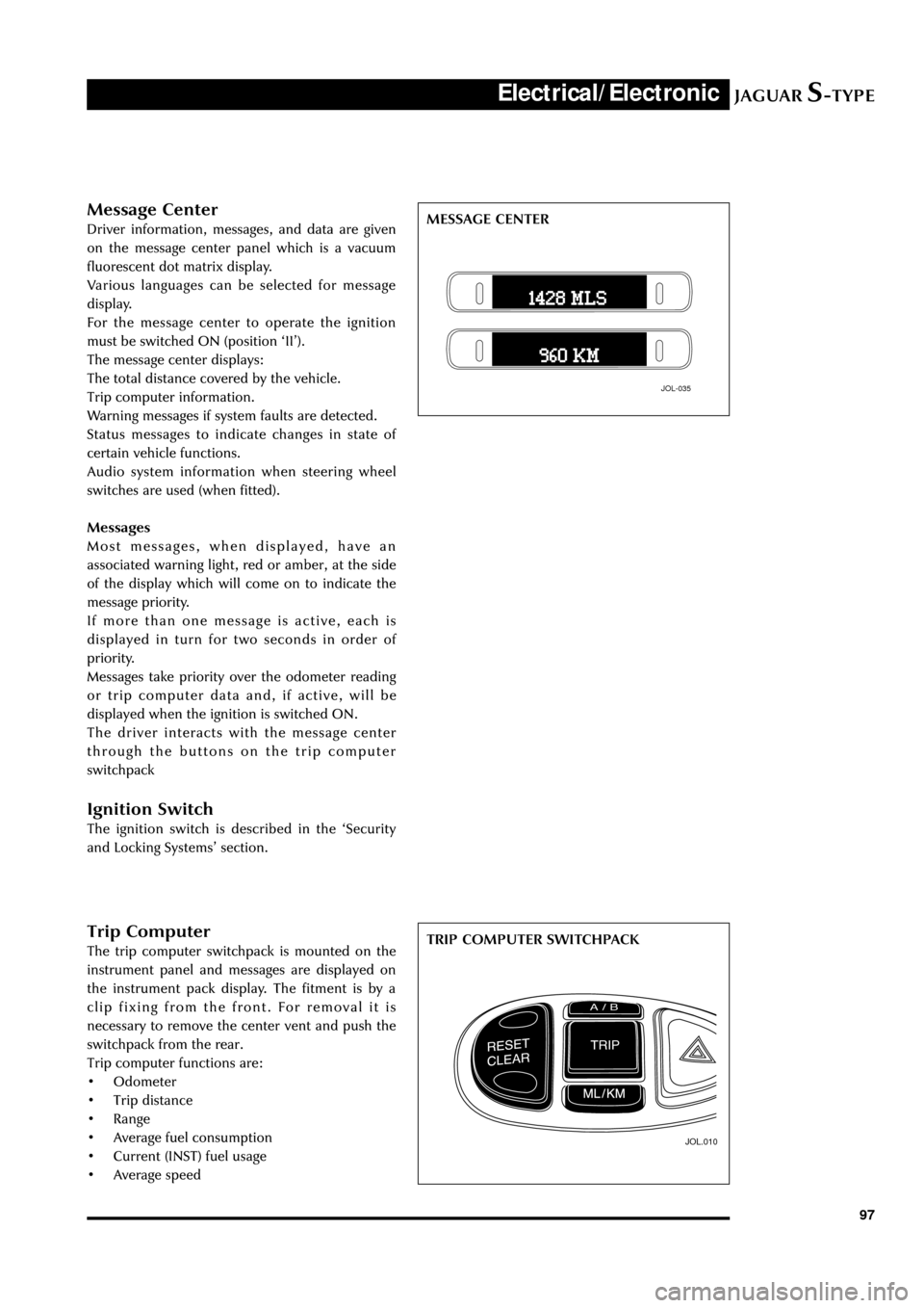
Trip Computer
The trip computer switchpack is mounted on the
instrument panel and messages are displayed on
the instrument pack display. The fitment is by a
clip fixing from the front. For removal it is
necessary to remove the center vent and push the
switchpack from the rear.
Trip computer functions are:
¥ Odometer
¥ Trip distance
¥ Range
¥ Average fuel consumption
¥ Current (INST) fuel usage
¥ Average speed
JOL.010
TRIP COMPUTER SWITCHPACK
Message Center
Driver information, messages, and data are given
on the message center panel which is a vacuum
fluorescent dot matrix display.
Various languages can be selected for message
display.
For the message center to operate the ignition
must be switched ON (position ÔIIÕ).
The message center displays:
The total distance covered by the vehicle.
Trip computer information.
Warning messages if system faults are detected.
Status messages to indicate changes in state of
certain vehicle functions.
Audio system information when steering wheel
switches are used (when fitted).
Messages
Most messages, when displayed, have an
associated warning light, red or amber, at the side
of the display which will come on to indicate the
message priority.
If more than one message is active, each is
displayed in turn for two seconds in order of
priority.
Messages take priority over the odometer reading
or trip computer data and, if active, will be
displayed when the ignition is switched ON.
The driver interacts with the message center
through the buttons on the trip computer
switchpack
Ignition Switch
The ignition switch is described in the ÔSecurity
and Locking SystemsÕ section.
JOL-035
MESSAGE CENTER
Page 103 of 133
JAGUARS-TYPEElectrical/Electronic
98Reset/Clear - Two position rocker switch. Sets the selected trip to zero. Clear can be used to cycle
though: TRIP - ODOMETER - MESSAGES. Clear can hide messages on the message
center.
Mls/Km - Selects metric or imperial data. Also selects languages Those available are:
English, US English, German, Spanish, Italian, French, Dutch, Finnish, Swedish,
Brazilian/Portuguese and Japanese
Trip/Cycle - Successive presses of the switch will display each of the trip data items and the
odometer reading , in turn.
A/B - Selects either A or B trip memory.
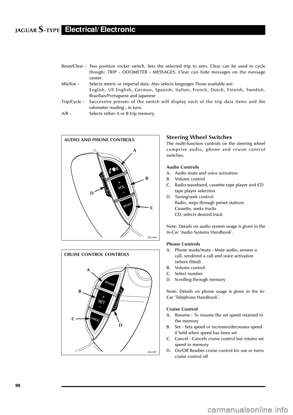
Steering Wheel Switches
The multi-function controls on the steering wheel
comprise audio, phone and cruise control
switches.
Audio Controls
A. Audio mute and voice activation
B. Volume control
C. Radio waveband, cassette tape player and CD
tape player selection
D. Tuning/seek control:
Radio, steps through preset stations
Cassette, seeks tracks
CD, selects desired track
Note: Details on audio system usage is given in the
In-Car ÔAudio Systems HandbookÕ.
Phone Controls
A. Phone mode/mute - Mute audio, answer a
call, send/end a call and voice activation
(where fitted)
B. Volume control
C. Select number
D. Scrolling through memory
Note: Details on phone usage is given in the In-
Car ÔTelephone HandbookÕ.
Cruise Control
A. Resume - To resume the set speed retained in
the memory
B. Set - Sets speed or increases/decreases speed
if held when speed has been set
C. Cancel - Cancels cruise control but retains set
speed in memory
D. On/Off Readies cruise control for use or turns
cruise control off
A
D
C B AUDIO AND PHONE CONTROLS
CRUISE CONTROL CONTROLS
A
D CB
JOL.044
JOL.007