service JAGUAR S TYPE 2005 1.G Technical Guide Update
[x] Cancel search | Manufacturer: JAGUAR, Model Year: 2005, Model line: S TYPE, Model: JAGUAR S TYPE 2005 1.GPages: 133, PDF Size: 3.48 MB
Page 2 of 133

Published by Service CommunicationsJaguar Cars LimitedPublication Part No JJM 10 15 16/92 February 1999
Page 4 of 133

Technical Guide
Jaguar S-TYPE
Sports Sedan
Introduction
Published by Service CommunicationsJaguar Cars LimitedPublication Part No JJM 10 15 16/92 February 1999
Page 5 of 133
JAGUARS-TYPEPreface
This Technical Guide introduces the Jaguar S-TYPE sports sedan which is a new addition to the Jaguar
range. It is intended to give Jaguar Dealer workshop personnel an overview of their construction and
operation, and is for information purposes only. The contents of this Technical Guide must not be used
as a reference source for servicing procedures; all servicing procedures must be in accordance with the
appropriate Service Manual.
This Technical Guide will not be updated. While every effort is made to ensure accuracy, changes may
occur between going to press and the equipment being introduced to the market. Once the equipment is
in service, details of changes can be obtained from Service Bulletins and revisions to the Service
Manuals.
All rights reserved. No part of this publication may be reproduced, stored in a retrieval system or
transmitted, in any form, electronic, mechanical, photocopying, recording or other means without prior
written permission from the Service Division of Jaguar Cars Limited.
Page 25 of 133

JAGUARS-TYPEBody
20system mirrors. A clear patch in the darkened
area at the bottom left of the windshield gives
external visible access to the VIN.
There are three types of windshield variants:
¥ Rain sensing, with electrochromic mirror
(NAS markets have the option of a compass
fitted to the mirror head).
¥ Non-rain sensing with electrochromic mirror
(NAS markets have the option of a compass
fitted to the mirror head).
¥ Non-rain sensing with prismatic mirror.
Windshields are available as heated or non-
heated and the rain sensing versions have a
unique mirror mounting system.
Backlight
The backlight is direct glazed to body. All
backlights are heated and have solar control tint,
integral radio and telephone antenna. The
backlight heater is timed on for 10 minutes.
Door glass
Each front door window is single curvature glass,
5mm thick, and operated by a twin guide cable
and drum assembly with five stud fixing points.
The glass is clamped to the regulator slide blocks.
Access holes are provided in the inner door when
the glass is raised. There are no adjustable end of
travel stops.
Rear door glass is also a single curvature glass,
4mm thick, with a single guide cable and drum
assembly and three stud fixing points. The glass
drops fully to the door roll. The glass is located to
the slider blocks by pins and has no adjustable
end of travel stops.
Each front and rear cable and drum mechanisms
must be replaced as individual complete units,
they have no serviceable parts.
Quarter lights
Quarter lights are 4mm thick with three fixings,
one is a lower bracket to the door inner.
Perimeter foam and butyl rubber seals are fitted
to the door outer.
Page 26 of 133
JAGUARS-TYPEBody
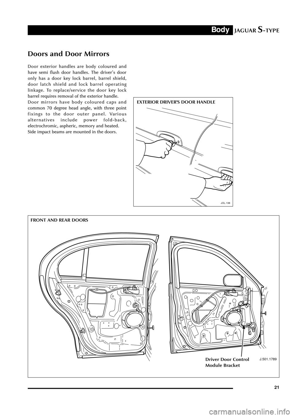
21 Door exterior handles are body coloured and
have semi flush door handles. The driverÕs door
only has a door key lock barrel, barrel shield,
door latch shield and lock barrel operating
linkage. To replace/service the door key lock
barrel requires removal of the exterior handle.
Door mirrors have body coloured caps and
common 70 degree head angle, with three point
fixings to the door outer panel. Various
alternatives include power fold-back,
electrochromic, aspheric, memory and heated.
Side impact beams are mounted in the doors.
Doors and Door Mirrors
EXTERIOR DRIVERÕS DOOR HANDLE
JOL.138
J.501.1789
FRONT AND REAR DOORS
Driver Door Control
Module Bracket
Page 37 of 133
JAGUARS-TYPEOccupant Protection
32
Seatbelts
D.501.1777
REAR SEAT BELT RETRACTOR ASSEMBLIES
D.501.1465
FRONT SEAT BELT PRE-TENSIONERFront Seatbelts and Pre-tensioners
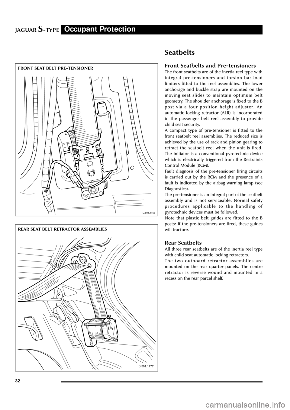
The front seatbelts are of the inertia reel type with
integral pre-tensioners and torsion bar load
limiters fitted to the reel assemblies. The lower
anchorage and buckle strap are mounted on the
moving seat slides to maintain optimum belt
geometry. The shoulder anchorage is fixed to the B
post via a four position height adjuster. An
automatic locking retractor (ALR) is incorporated
in the passenger belt reel assembly to provide
child seat security.
A compact type of pre-tensioner is fitted to the
front seatbelt reel assemblies. The reduced size is
achieved by the use of rack and pinion gearing to
retract the seatbelt reel when the unit is fired.
The initiator is a conventional pyrotechnic device
which is electrically triggered from the Restraints
Control Module (RCM).
Fault diagnosis of the pre-tensioner firing circuits
is carried out by the RCM and the presence of a
fault is indicated by the airbag warning lamp (see
Diagnostics).
The pre-tensioner is an integral part of the seatbelt
assembly and is not serviceable. Normal safety
procedures applicable to the handling of
pyrotechnic devices must be followed.
Note that plastic belt guides are fitted to the B
posts: if the pre-tensioners are fired, these guides
will fracture.
Rear Seatbelts
All three rear seatbelts are of the inertia reel type
with child seat automatic locking retractors.
The two outboard retractor assemblies are
mounted on the rear quarter panels. The centre
retractor is reverse wound and mounted in a
recess on the rear parcel shelf.
D.501.1465
Page 41 of 133
JAGUARS-TYPE
D.418.233
Occupant Protection
36
Restraints Control Module (RCM)
The RCM:
¥ Houses the electro-mechanical safing sensor
and electronic discrimination sensor which
detect a frontal impact.
¥ Houses the electronic safing sensor to detect
a side impact.
¥ Identifies severity and direction of impact
and makes decision on deployment of airbags
and pre-tensioners.
¥ Provides firing signals to all airbags and pre-
tensioners.
¥ Performs on board testing of the airbag and
pretensioner firing circuits, warning indicator
circuits and module status (Side Impact
Sensor performs its own internal checks).
¥ Stores fault codes in non-volatile memory.
¥ Drives the airbag warning lamp on the
instrument pack: if the warning lamp is
faulty (fault code recorded) an audible
warning tone is sounded.
¥ In the event of an impact, sends a signal to
the vehicle emergency message system
(VEMS) and the PCM to indicate that a crash
has occurred.
¥ Is connected to the data link connector via
the SCP data bus to enable communication
with an external PDU or scan tool.
¥ Provides temporary back-up power to operate
the airbags in the event of loss of battery
supply in an impact.
¥ In the event of an impact, records certain
data for subsequent access via the data link
connector. This data includes deceleration
information, firing delay and fault codes.
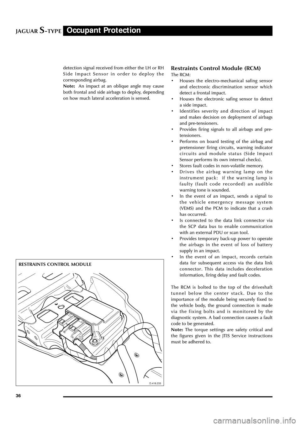
The RCM is bolted to the top of the driveshaft
tunnel below the center stack. Due to the
importance of the module being securely fixed to
the vehicle body, the ground connection is made
via the fixing bolts and is monitored by the
diagnostic system. A bad connection causes a fault
code to be generated.
Note:The torque settings are safety critical and
the figures given in the JTIS Service instructions
must be adhered to. RESTRAINTS CONTROL MODULE
D.418.233
detection signal received from either the LH or RH
Side Impact Sensor in order to deploy the
corresponding airbag.
Note:An impact at an oblique angle may cause
both frontal and side airbags to deploy, depending
on how much lateral acceleration is sensed.
Page 47 of 133
JAGUARS-TYPEFuel System
42
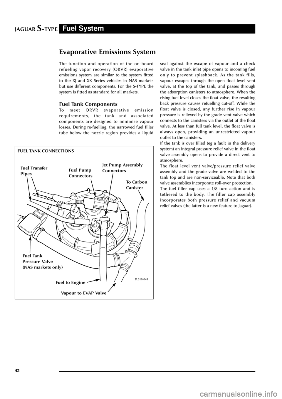
Evaporative Emissions System
The function and operation of the on-board
refueling vapor recovery (ORVR) evaporative
emissions system are similar to the system fitted
to the XJ and XK Series vehicles in NAS markets
but use different components. For the S-TYPE the
system is fitted as standard for all markets.
Fuel Tank Components
To meet ORVR evaporative emission
requirements, the tank and associated
components are designed to minimise vapour
losses. During re-fuelling, the narrowed fuel filler
tube below the nozzle region provides a liquidseal against the escape of vapour and a check
valve in the tank inlet pipe opens to incoming fuel
only to prevent splashback. As the tank fills,
vapour escapes through the open float level vent
valve, at the top of the tank, and passes through
the adsorption canisters to atmosphere. When the
rising fuel level closes the float valve, the resulting
back pressure causes refuelling cut-off. While the
float valve is closed, any further rise in vapour
pressure is relieved by the grade vent valve which
connects to the canisters via the outlet of the float
valve. At less than full tank level, the float valve is
always open, providing an unrestricted vapour
outlet to the canisters.
If the tank is over filled (eg a fault in the delivery
system) an integral pressure relief valve in the float
valve assembly opens to provide a direct vent to
atmosphere.
The float level vent valve/pressure relief valve
assembly and the grade valve are welded to the
tank top and are non-serviceable. Note that both
valve assemblies incorporate roll-over protection.
The fuel filler cap uses a 1/8 turn action and is
tethered to the body. The filler cap assembly
incorporates both pressure relief and vacuum
relief valves (the latter is a new feature to Jaguar).
D.310.049
FUEL TANK CONNECTIONS
Fuel Tank
Pressure Valve
(NAS markets only)
Jet Pump Assembly
Connectors
Fuel Pump
Connectors
To Carbon
Canister
Vapour to EVAP Valve
Fuel to Engine
Fuel Transfer
Pipes
Page 50 of 133
JAGUARS-TYPETransmission
45
Introduction
The automatic and manual transmission units are
described in the ÔS-TYPE Sports Sedan Powertrain
IntroductionÕ Technical Guide.
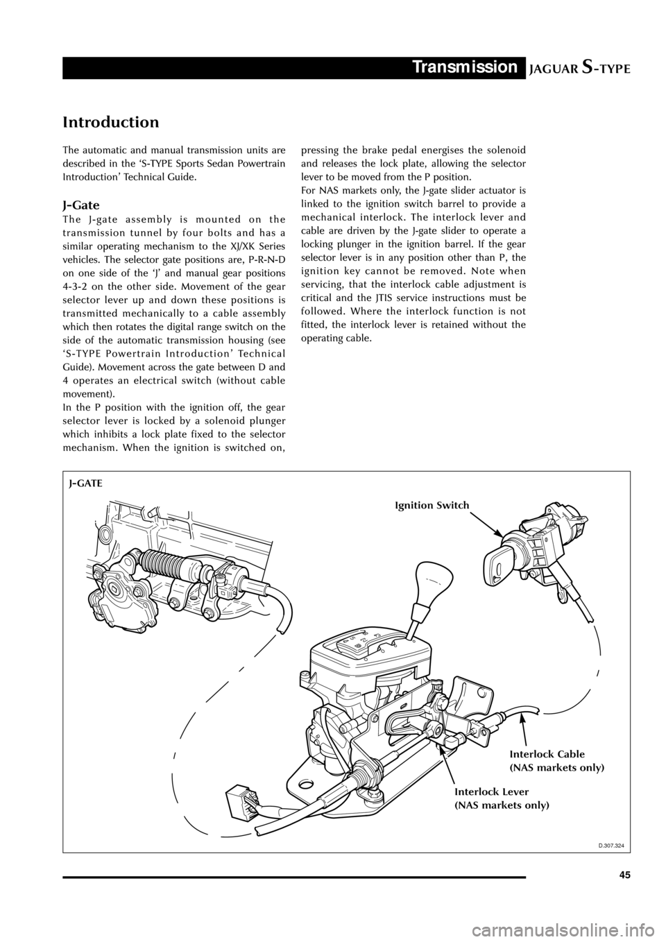
J-Gate
The J-gate assembly is mounted on the
transmission tunnel by four bolts and has a
similar operating mechanism to the XJ/XK Series
vehicles. The selector gate positions are, P-R-N-D
on one side of the ÔJÕ and manual gear positions
4-3-2 on the other side. Movement of the gear
selector lever up and down these positions is
transmitted mechanically to a cable assembly
which then rotates the digital range switch on the
side of the automatic transmission housing (see
ÔS-TYPE Powertrain IntroductionÕ Technical
Guide). Movement across the gate between D and
4 operates an electrical switch (without cable
movement).
In the P position with the ignition off, the gear
selector lever is locked by a solenoid plunger
which inhibits a lock plate fixed to the selector
mechanism. When the ignition is switched on,pressing the brake pedal energises the solenoid
and releases the lock plate, allowing the selector
lever to be moved from the P position.
For NAS markets only, the J-gate slider actuator is
linked to the ignition switch barrel to provide a
mechanical interlock. The interlock lever and
cable are driven by the J-gate slider to operate a
locking plunger in the ignition barrel. If the gear
selector lever is in any position other than P, the
ignition key cannot be removed. Note when
servicing, that the interlock cable adjustment is
critical and the JTIS service instructions must be
followed. Where the interlock function is not
fitted, the interlock lever is retained without the
operating cable.
D.307.324
J-GATE
Ignition Switch
Interlock Cable
(NAS markets only)
Interlock Lever
(NAS markets only)
D.307.324
Page 52 of 133
JAGUARS-TYPEChassis
47
Front Suspension
The independent front wheel suspension is a
double wishbone axle arrangement with
aluminium control arms. The two arms are of
different lengths, which minimises the changes in
track and camber. Inclination of the upper control
arm axis provides anti-dive front suspension
action. There are two front cross members,
known as Number 1 and Number 2.
Number 1, the forward cross member, is a steel
fabrication, non-isolated, which locates the lower
control arm front mounting, the anti-roll bar and
the cooling module.
The rear cross member, Number 2, is an
aluminium casting, non-isolated and it locates the
lower control arm rear mounting, the power
steering rack and the engine hydro-mounts.
WARNING: No attempt must be made to
weld or repair the aluminium cross
member. If it is damaged, a new one must
be installed.
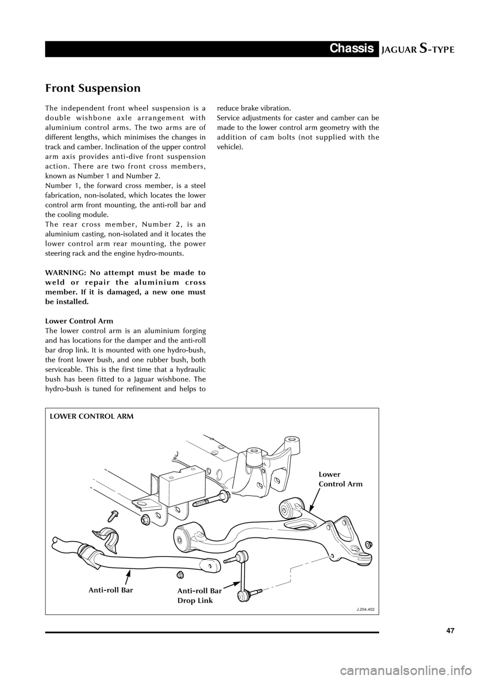
Lower Control Arm
The lower control arm is an aluminium forging
and has locations for the damper and the anti-roll
bar drop link. It is mounted with one hydro-bush,
the front lower bush, and one rubber bush, both
serviceable. This is the first time that a hydraulic
bush has been fitted to a Jaguar wishbone. The
hydro-bush is tuned for refinement and helps to
J.204.402
reduce brake vibration.
Service adjustments for caster and camber can be
made to the lower control arm geometry with the
addition of cam bolts (not supplied with the
vehicle).
LOWER CONTROL ARM
J.204.402
Lower
Control Arm
Anti-roll BarAnti-roll Bar
Drop Link