wheel bolts JAGUAR S TYPE 2005 1.G Technical Guide Update
[x] Cancel search | Manufacturer: JAGUAR, Model Year: 2005, Model line: S TYPE, Model: JAGUAR S TYPE 2005 1.GPages: 133, PDF Size: 3.48 MB
Page 52 of 133

JAGUARS-TYPEChassis
47
Front Suspension
The independent front wheel suspension is a
double wishbone axle arrangement with
aluminium control arms. The two arms are of
different lengths, which minimises the changes in
track and camber. Inclination of the upper control
arm axis provides anti-dive front suspension
action. There are two front cross members,
known as Number 1 and Number 2.
Number 1, the forward cross member, is a steel
fabrication, non-isolated, which locates the lower
control arm front mounting, the anti-roll bar and
the cooling module.
The rear cross member, Number 2, is an
aluminium casting, non-isolated and it locates the
lower control arm rear mounting, the power
steering rack and the engine hydro-mounts.
WARNING: No attempt must be made to
weld or repair the aluminium cross
member. If it is damaged, a new one must
be installed.
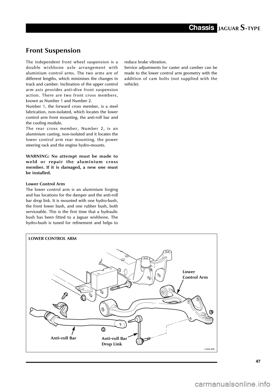
Lower Control Arm
The lower control arm is an aluminium forging
and has locations for the damper and the anti-roll
bar drop link. It is mounted with one hydro-bush,
the front lower bush, and one rubber bush, both
serviceable. This is the first time that a hydraulic
bush has been fitted to a Jaguar wishbone. The
hydro-bush is tuned for refinement and helps to
J.204.402
reduce brake vibration.
Service adjustments for caster and camber can be
made to the lower control arm geometry with the
addition of cam bolts (not supplied with the
vehicle).
LOWER CONTROL ARM
J.204.402
Lower
Control Arm
Anti-roll BarAnti-roll Bar
Drop Link
Page 55 of 133

JAGUARS-TYPEChassis
50
D.204.399
FRONT SPRING AND DAMPER
D.204.399
Wheel Alignment
Camber caster and toe are adjustable on the front
suspension only. Toe is the only adjustment on the
rear suspension. Camber and caster are adjusted
by means of eccentric cams on the lower control
arm mounting bolts. The front toe is adjusted by
use of the front tie rod. The rear toe is adjusted by
the use of toe link assemblies connecting the
knuckles to the rear sub-frame.
Anti-roll Bars
There are two types of front anti-roll bars, one for
all V6 and base V8 engined vehicles and one for
V8 sport. There are two types of rear anti-roll
bars, one for all V6 and base V8 engined vehicles
and one for V8 sport.
All anti-roll bars are similar to current saloon
except that the front bushes have moulded insert
for tuning.
Springs and Dampers
There are numerous variants to suit both
ÔstandardÕ and ÔsportÕ derivatives of the V6 and V8
engined vehicles. Both front and rear springs and
dampers are similar to current sports vehicles.
With a strut type assembly, integrated top mount
and two-position lower spring pan. The front and
rear co-axial strut and spring assemblies are
installed between the lower control arms and the
vehicle body.
Sports dampers are CATS only, as XK series.
The CATS suspension is similar to the system
introduced on the XK8. It is a two-stage adaptive
damping ride control. The control module is
located in the rear left-hand corner of the spare
wheel well. Three accelerometers are fitted. The
front vertical and lateral accelerometers are
mounted as an assembly to the vapour
management valve bracket. The lateral
D.204.401
the A-frame bush on current sports and saloon
vehicles. The bushes are not bonded in place but
require a special lubricant when assembling. Care
must be taken to ensure that the replacement
bushes are pushed fully home, the angular
orientation of the bushes is important and it is
essential to mark the position of the subframe
before removing from the vehicle or else driveline
alignment will be lost.
REAR SPRING AND DAMPER
D.204.401
Page 65 of 133

JAGUARS-TYPEChassis
60
D.211.255
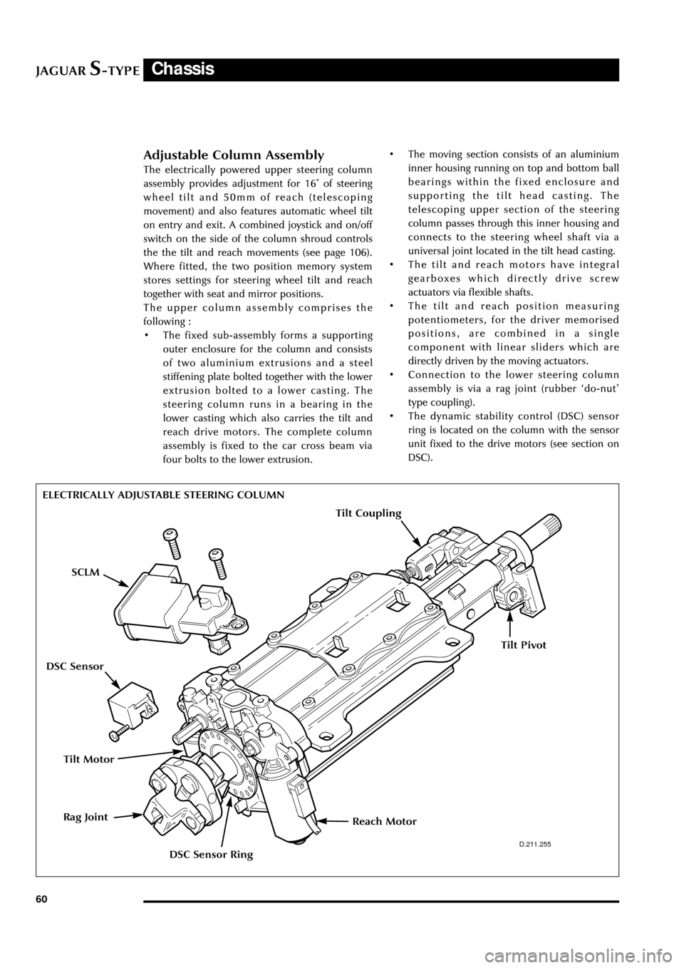
ELECTRICALLY ADJUSTABLE STEERING COLUMN
Adjustable Column Assembly
The electrically powered upper steering column
assembly provides adjustment for 16û of steering
wheel tilt and 50mm of reach (telescoping
movement) and also features automatic wheel tilt
on entry and exit. A combined joystick and on/off
switch on the side of the column shroud controls
the the tilt and reach movements (see page 106).
Where fitted, the two position memory system
stores settings for steering wheel tilt and reach
together with seat and mirror positions.
The upper column assembly comprises the
following :
¥ The fixed sub-assembly forms a supporting
outer enclosure for the column and consists
of two aluminium extrusions and a steel
stiffening plate bolted together with the lower
extrusion bolted to a lower casting. The
steering column runs in a bearing in the
lower casting which also carries the tilt and
reach drive motors. The complete column
assembly is fixed to the car cross beam via
four bolts to the lower extrusion.¥ The moving section consists of an aluminium
inner housing running on top and bottom ball
bearings within the fixed enclosure and
supporting the tilt head casting. The
telescoping upper section of the steering
column passes through this inner housing and
connects to the steering wheel shaft via a
universal joint located in the tilt head casting.
¥ The tilt and reach motors have integral
gearboxes which directly drive screw
actuators via flexible shafts.
¥ The tilt and reach position measuring
potentiometers, for the driver memorised
positions, are combined in a single
component with linear sliders which are
directly driven by the moving actuators.
¥ Connection to the lower steering column
assembly is via a rag joint (rubber Ôdo-nutÕ
type coupling).
¥ The dynamic stability control (DSC) sensor
ring is located on the column with the sensor
unit fixed to the drive motors (see section on
DSC).
Tilt Motor
Reach MotorRag Joint
SCLM
DSC Sensor Ring
DSC Sensor
Tilt Coupling
Tilt Pivot