head bolt JAGUAR X308 1998 2.G Workshop Manual
[x] Cancel search | Manufacturer: JAGUAR, Model Year: 1998, Model line: X308, Model: JAGUAR X308 1998 2.GPages: 2490, PDF Size: 69.81 MB
Page 2316 of 2490
Wipers and Washers - Windshield Wiper MotorVehicles Built Up To:
10/1997
Removal and Installation
Removal
1. Remove battery cover and disc onnect ground cable from
battery terminal. Refer to 86.15.19.
2. Remove top covers from LH an d RH bulkheads and rear of
engine compartment. Refer to 76.11.33 and 76.11.35.
3. Remove wiper arm and blade as sembly. Refer to 84.15.44.90.
4. Remove plenum cover. Refer to 76.10.01
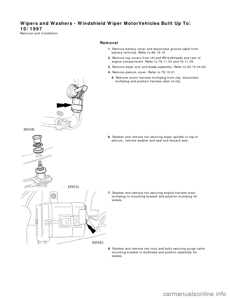
5. Remove motor harness multiplug from clip, disconnect
multiplug and position harness clear of clip.
6. Slacken and remove nut securi ng wiper spindle to top of
plenum, remove washer and seal and discard seal.
7. Slacken and remove nut securing engine harness main
multiplug to mounting bracke t and position multiplug for
access.
8. Slacken and remove two nuts an d bolts securing purge valve
mounting bracket to bulkhead and position assembly for
access.
Page 2317 of 2490
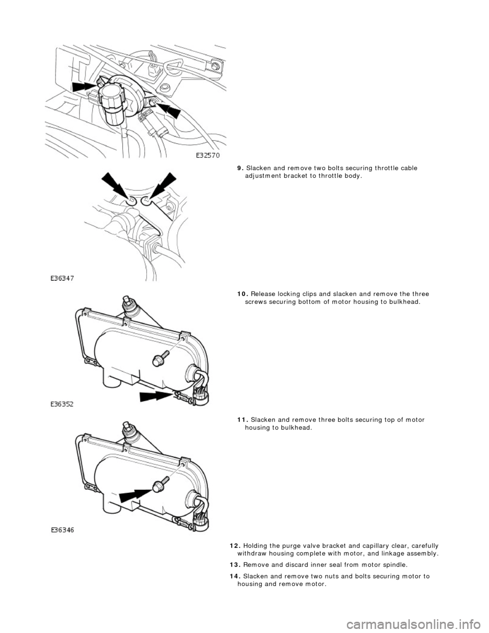
9. Slacken and remove two bolts securing throttle cable
adjustment bracket to throttle body.
10. Release locking clips and sl acken and remove the three
screws securing bottom of motor housing to bulkhead.
11. Slacken and remove three bo lts securing top of motor
housing to bulkhead.
12. Holding the purge valve bracket and capillary clear, carefully
withdraw housing complete with motor, and linkage assembly.
13. Remove and discard inner seal from motor spindle.
14. Slacken and remove two nuts and bolts securing motor to
housing and remove motor.
Page 2318 of 2490

Installation
1.
Position motor in housing and fi t and tighten securing nuts and
bolts.
2. Apply suitable lubricant to bore of new spindle inner seal and
fit seal over motor spindle.
3. Holding the capillary and purge valve clear, position
motor/housing assembly on bulkhead.
4. Seat motor spindle seal correctly in upper plenum aperture and
ensure that housing lo cates on lower studs.
5. Fit and tighten the housin g upper securing bolts.
6. Fit and tighten the housing lower securing screws and slide
locking clips inwards.
7. Position throttle cable adjustment bracket on throttle body and
fit and tighten securing bolts.
8. Position purge valve bracket at bulkhead and fit and tighten
securing bolt and nuts.
9. Position engine harness multiplu g on mounting bracket and fit
and tighten securing nut.
10. Connect motor harness multiplug and locate in retaining clip.
11. Apply suitable lubricant to bore of new outer seal and fit with
washer to motor spindle.
12. Fit and fully tighten collar nut on motor spindle.
13. Fit plenum cover. Refer to 76.10.01.
14. Fit wiper arm and blade. Refer to 84.15.44.90.
15. Fit top covers to LH and RH bulkheads and rear of engine
compartment. refer to 76.11.33 and 76.11.35.
16. Fit ground cable to battery te rminal and cover to battery.
Refer to 86.15.15.
Page 2319 of 2490
Wipers and Washers - Windshield Wiper MotorVehicles Built From:
10/1997
Removal and Installation
Removal
1. Remove battery cover and disc onnect ground cable from
battery terminal. Refer to 86.15.19.
2. Remove top covers from LH an d RH bulkheads and rear of
engine compartment. Refer to 76.11.33 and 76.11.35.
3. Remove wiper arm and blade as sembly. Refer to 84.15.44.90.
4. Remove plenum cover. Refer to 76.10.01
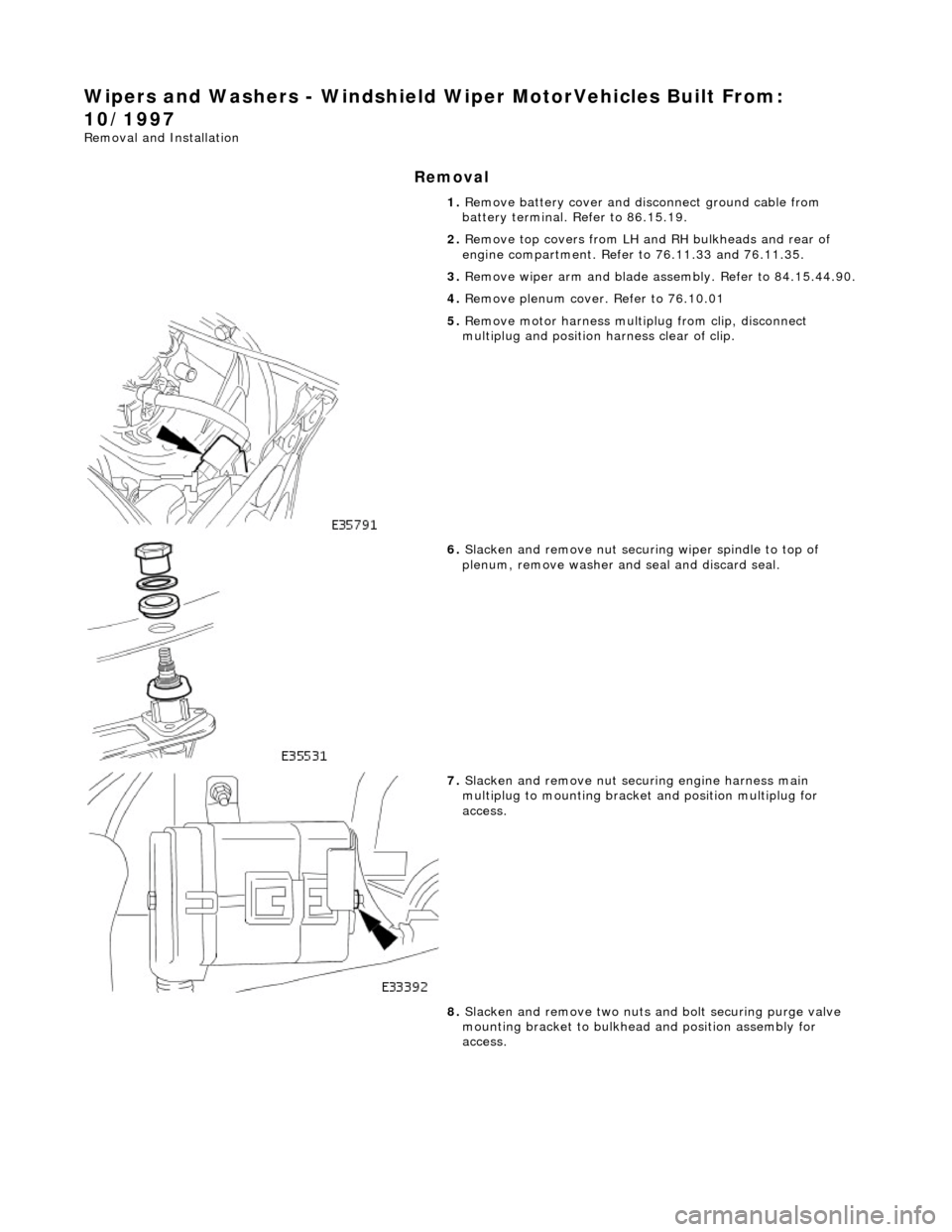
5. Remove motor harness multiplug from clip, disconnect
multiplug and position harness clear of clip.
6. Slacken and remove nut securi ng wiper spindle to top of
plenum, remove washer and seal and discard seal.
7. Slacken and remove nut securing engine harness main
multiplug to mounting bracke t and position multiplug for
access.
8. Slacken and remove two nuts an d bolt securing purge valve
mounting bracket to bulkhead and position assembly for
access.
Page 2320 of 2490
Installation
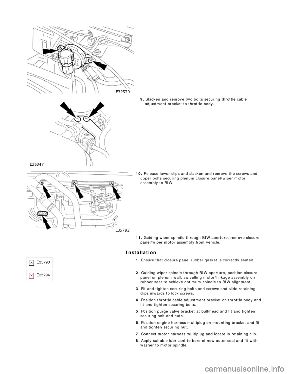
9. Slacken and remove two bolts securing throttle cable
adjustment bracket to throttle body.
10. Release lower clips and slacken and remove the screws and
upper bolts securing plenum closure panel/wiper motor
assembly to BIW.
11. Guiding wiper spindle through BIW aperture, remove closure
panel/wiper motor assembly from vehicle.
E357931. Ensure that closure panel rubbe r gasket is correctly seated.
E357942. Guiding wiper spindle through BI W aperture, position closure
panel on plenum wall, swivelling motor/linkage assembly on
rubber seat to achieve optimu m spindle to BIW alignment.
3. Fit and tighten securing bolts and screws and slide retaining
clips inwards to lock screws.
4. Position throttle cable adjustment bracket on throttle body and
fit and tighten securing bolts.
5. Position purge valve bracket at bulkhead and fit and tighten
securing bolt and nuts.
6. Position engine harness multiplu g on mounting bracket and fit
and tighten securing nut.
7. Connect motor harness multiplug and locate in retaining clip.
8. Apply suitable lubricant to bore of new outer seal and fit with
washer to motor spindle.
Page 2332 of 2490
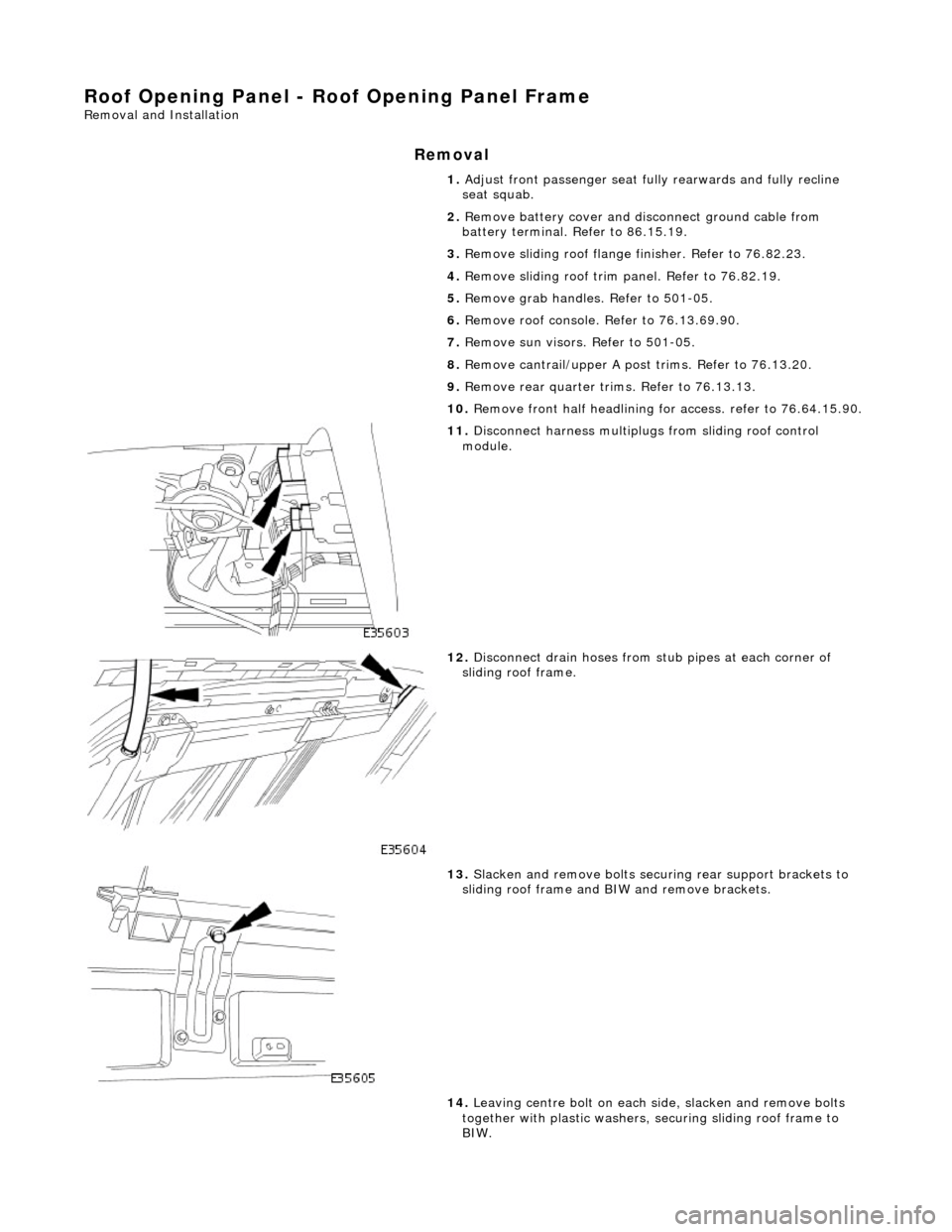
Roof Opening Panel - Roof Opening Panel Frame
Removal and Installation
Removal
1. Adjust front passenger seat fu lly rearwards and fully recline
seat squab.
2. Remove battery cover and disc onnect ground cable from
battery terminal. Refer to 86.15.19.
3. Remove sliding roof flange finisher. Refer to 76.82.23.
4. Remove sliding roof trim panel. Refer to 76.82.19.
5. Remove grab handles. Refer to 501-05.
6. Remove roof console. Refer to 76.13.69.90.
7. Remove sun visors. Refer to 501-05.
8. Remove cantrail/upper A post trims. Refer to 76.13.20.
9. Remove rear quarter trim s. Refer to 76.13.13.
10. Remove front half headlining for access. refer to 76.64.15.90.
11. Disconnect harness multiplugs from sliding roof control
module.
12. Disconnect drain hoses from stub pipes at each corner of
sliding roof frame.
13. Slacken and remove bolts securi ng rear support brackets to
sliding roof frame and BIW and remove brackets.
14. Leaving centre bolt on each side, slacken and remove bolts
together with plastic washers, securing sliding roof frame to
BIW.
Page 2334 of 2490
tighten securing bolts.
7.
Align rear support brackets and tighten securing bolts.
8. Connect drain hoses to sliding roof frame stub pipes.
9. Fit headlining. Refer to 76.64.15.90.
10. Fit rear quarter trims. Refer to 76.13.13.
11. Fit cantrail/upper A post trims. Refer to 76.13.20.
12. Fit sun visors. Refer to 501-05.
13. Fit roof console. Refer to 76.13.69.90.
14. Fit grab handles. Refer to 501-05.
15. Fit sliding roof trim panel. Refer to 76.82.19.
16. Fit sliding roof flange fi nisher. Refer to 76.82.23.
17. Connect ground cable to batt ery terminal and fit battery
cover. Refer to 86.15.15.
18. Return front passen ger seat to original positions.
Page 2344 of 2490
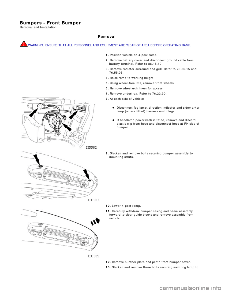
Bumpers - Front Bumper
Removal and Installation
Removal
WARNING: ENSURE THAT ALL PERSONNEL AND EQUIPMENT ARE CLEAR OF AREA BEFORE OPERATING RAMP.
1. Position vehicle on 4-post ramp.
2. Remove battery cover and disc onnect ground cable from
battery terminal. Refer to 86.15.19
3. Remove radiator surround and grill. Refer to 76.55.15 and
76.55.03.
4. Raise ramp to working height.
5. Using wheel-free lifts, remove front wheels.
6. Remove wheelarch liners for access.
7. Remove undertray. Refer to 76.22.90.
8. At each side of vehicle:
Disconnect fog lamp, directio n indicator and sidemarker
lamp (where fitted) harness multiplugs.
If headlamp powerwash is fitted, remove and discard
plastic clip from hose and disconnect hose at RH side of
bumper.
9. Slacken and remove bolts securing bumper assembly to
mounting struts.
10. Lower 4-post ramp.
11. Carefully withdraw bumper casing and beam assembly
forward to clear guide blocks and remove assembly from
vehicle.
12. Remove number plate and plinth from bumper cover.
13. Slacken and remove three bolts securing each fog lamp to
Page 2347 of 2490
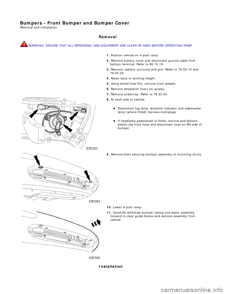
Bumpers - Front Bumper and Bumper Cover
Removal and Installation
Removal
WARNING: ENSURE THAT ALL PERSONNEL AND EQUIPMENT ARE CLEAR OF AREA BEFORE OPERATING RAMP.
Installation
1. Position vehicle on 4-post ramp.
2. Remove battery cover and disc onnect ground cable from
battery terminal. Refer to 86.15.19.
3. Remove radiator surround and grill. Refer to 76.55.15 and
76.55.03.
4. Raise ramp to working height.
5. Using wheel-free lifts, remove front wheels.
6. Remove wheelarch liners for access.
7. Remove undertray. Refer to 76.22.90.
8. At each side of vehicle:
Disconnect fog lamp, directio n indicator and sidemarker
lamp (where fitted) harness multiplugs.
If headlamp powerwash is fitted, remove and discard
plastic clip from hose and disconnect hose on RH side of
bumper.
9. Remove bolts securing bumper assembly to mounting struts.
10. Lower 4-post ramp.
11. Carefully withdraw bumper casing and beam assembly
forward to clear guide blocks and remove assembly from
vehicle.
Page 2348 of 2490

1.
WARNING: ENSURE THAT ALL PERSONNEL AND
EQUIPMENT ARE CLEAR OF AREA BEFORE OPERATING RAMP.
Carefully slide bumper assembly onto fender guide blocks.
2. Raise ramp to working height.
3. Install but do not fully tighten bo lts securing bumper to struts.
4. Check clearance between top of bumper and bottom of fender.
If necessary, remove bumper, adjust guide blocks to achieve
correct clearance and refit bumper.
5. Connect harness multiplugs to foglamps, direction indicators
and where fitted side marker lamps.
6. Install harnesses in retaining clips at each side of cover.
7. Install powerwash hoses to jet assemblies and secure with new
plastic clips. Refer to Section 501.16.
8. Install radiator grill and su rround. refer to 76.55.03 and
76.55.15.
9. Check and as necessary adjust bumper cover to fender,
headlamps and radiator grill surround clearances. Refer to
Description and Operation in this section.
10. Fully tighten bumper assembly to strut securing bolts.
11. Install wheelarch liners.
12. Install undertray. Refer to 76.22.90.
13. Lower 4-post ramp.
14. Install road wheels and lower wheel-free lifts.